37 10si alternator wiring diagram
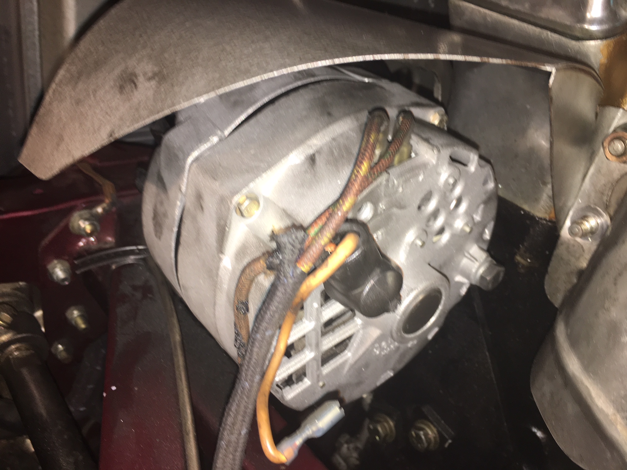
Looking at the diagram for the old alternator, there is a brown wire that goes from the regulator and over to the ACC on the IGN switch. I was thinking that was for switched power. Now, looking at the new harness there is a brown wire, shown in the photo, that is going from the 10SI alternator and I followed it through the harness to the dash ... GM 10SI. Internally. Regulated. Optional Charge Indicator Light Function: Your Powermaster Alternator is designed to work as a 1 wire without any ...1 page
25 Aug 2009 — I read all of the posts and found the proper wiring diagrams for a 3 wire 10si. I installed a new alternator (3 wire internal regulator) in ...
10si alternator wiring diagram
Apr 15, · GM 10Si alternator wiring issues. Discussion in 'The Hokey Ass Message Board' started by mikew, Aug 25, I read all of the posts and found the proper wiring diagrams for a 3 wire 10si. I installed a new alternator (3 wire internal regulator) in my '62 comet. The Red sense voltage is how the regulator senses voltage. Searching for details about 1 Wire Alternator Wiring Diagram? you are right below. ... GM 10Si alternator wiring issues. More information. 10Si Alternator Wiring Diagram Source: rpx-patents.s3.amazonaws.com 10Si Alternator Wiring Diagram Source: alternatorparts.com Read electrical wiring diagrams from bad to positive in addition to redraw the routine being a straight collection.
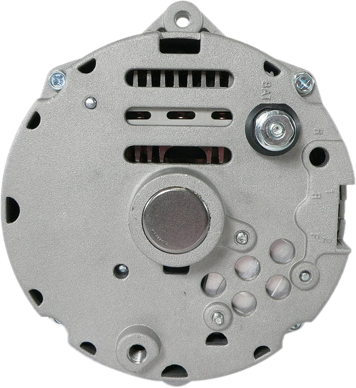
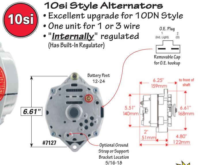
10si alternator wiring diagram. 10SI, 12SI & 15SI ALTERNATOR INSTALLATION INSTRUCTIONS. WARNING!!!!ALWAYS USE PROPER EYE PROTECTION WHEN PERFORMING ANY MECHANICAL REPAIRS TO A VEHICLE –. WIRING INSTRUCTIONS GM SI Alternator (One Wire or OE Hookup) Tech Dept. (630) 957-4019 Tech@powermasterperformance.com Replaces these OEM Alternators GM 10DN Externally Regulated GM 10SI Internally Optional Charge Indicator Light Function: Your Powermaster Alternator is designed to work as a 1 wire without any connections to the plug in. The Delco 10Si Alternator Wiring Diagram Collection. A wiring diagram is a schematic type that uses abstract illustrated symbols to show all of the components of a system. Wiring diagrams are made up of two things: symbols that represent the components of a circuit, and lines that represent the connections between them. 10si Alternator Wiring Diagram. All of the wiring diagrams I have seen have a wire from + through Hook the #1 alternator terminal to ACC and the tractor coil power to IGN. This diagram shows how to wire a Delco (GM) internally regulated 3-wire alternator. This particular model (10SI, used in the s and early 80s) is the one.
There are many 10si wiring diagrams out there, and the one Doc posted is a very common solution. BAT terminal (threaded post on the back of alternator) - This charge wire should be connected as directly as possible to the battery, using a fusible link for protection. A 10 gauge wire with 14 gauge fusible link will work for 10si's up to 63 amp. Wiring an alternator. This diagram shows how to wire a Delco (GM) internally regulated 3-wire alternator. This particular model (10SI, used in the 1970s and ... Delco 10Si Alternator Wiring Diagram Source: www.pirate4x4.com Delco 10Si Alternator Wiring Diagram Source: schematron.org Before reading a schematic, get familiar and understand all the symbols. 10Si Alternator Operating Principles. A typical 10Si series wiring diagram is illustrated in Figure 3. The basic operating principles are explained as follows.
Common Delco SI Series Alternator Wiring Diagram. by David Smith Sep 22, 2016. We are commonly asked how to wire the Delco SI series alternators upon maintenance or upgrading from an older generator. While this series of unit often runs as a self exciting one wire, agricultural applications also used 3 wire connections to the alternator. 10Si Alternator Operating Principles. A typical 10Si series wiring diagram is illustrated in Figure 3. The basic operating principles are explained as follows. The No. 2 terminal is connected to the battery, and the base-emitter of transistors TR4 and TR1 is connected to the battery through resistor R5, thus turning these transistors on ... 10Si Alternator Wiring Diagram Source: rpx-patents.s3.amazonaws.com 10Si Alternator Wiring Diagram Source: alternatorparts.com Read electrical wiring diagrams from bad to positive in addition to redraw the routine being a straight collection. Searching for details about 1 Wire Alternator Wiring Diagram? you are right below. ... GM 10Si alternator wiring issues. More information.
Apr 15, · GM 10Si alternator wiring issues. Discussion in 'The Hokey Ass Message Board' started by mikew, Aug 25, I read all of the posts and found the proper wiring diagrams for a 3 wire 10si. I installed a new alternator (3 wire internal regulator) in my '62 comet. The Red sense voltage is how the regulator senses voltage.

Buy Total Power Parts Adr0336 Alternator Compatible With Replacement For Chevy High Output 105 Amp 3 Wire 1965 1985 Adr0336 Online In Greece B07894t35q

Buy A Team Performance 1g Style Alternator 1 Wire 110 Amp 10si Conversion 1 Groove V Belt V6 And V8 Compatible With Ford 1965 89 Chrome Online In Indonesia B07h4gmf6b
_web.jpg)
John Deere 4020 Diesel Dash Engine Wire Harness Serial 91 000 200 999 12 Volt 10si Alternator The Brillman Company

2920 01 126 1585 10si Alternator 12v72a Type 116 136 Fits Gm 1105435 1102933 9 O Clock Dp Equipment Llc


0 Response to "37 10si alternator wiring diagram"
Post a Comment