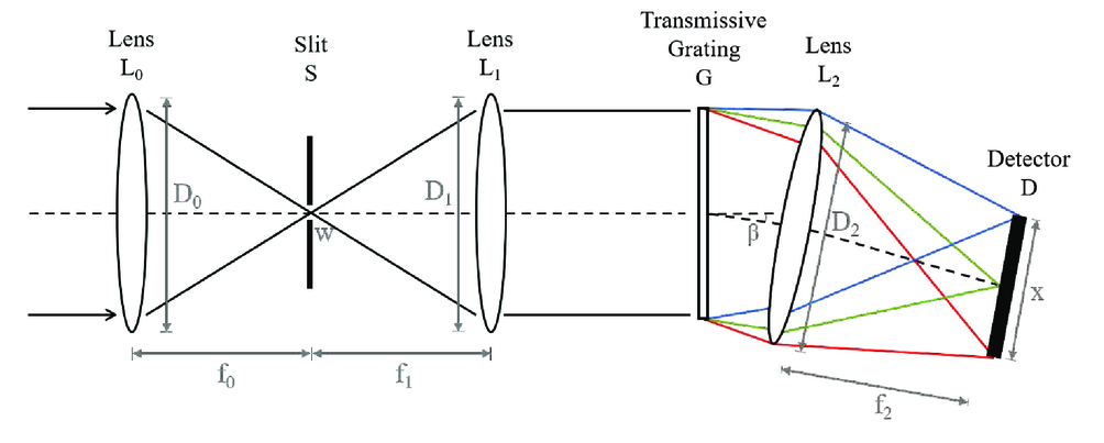
38 draw a ray diagram of the lens system you set up in c6
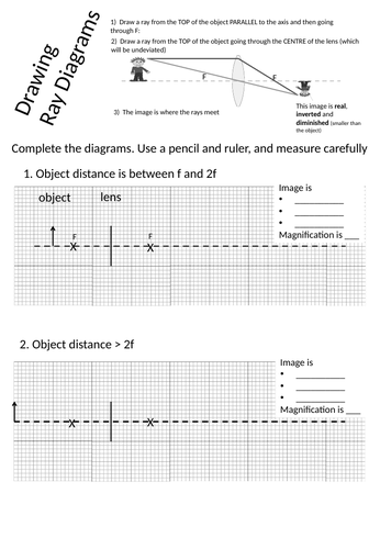
Ray diagram for an object placed between 2F and F from a convex lens In a film or data projector, this image is formed on a screen. Film must be loaded into the projector upside down so the ... a) For convenience of discussion we assume that the light passes through the lens from left to right. Ray diagrams will follow this convention. (b) The focal point of a lens is found by allowing a bundle of mutually parallel rays to enter the lens (i.e., from an object infinitely far from the lens). The lens alters the direction of these rays,
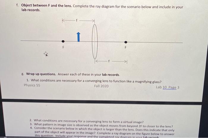
Draw a ray diagram to show how a converging lens can form a real and enlarged image of an object. Solution: The above figure shows the image formed is real, enlarged and inverted. Question: 16. A lens forms an upright and diminished image of an object placed at its focal point. Name the lens and draw a ray diagram to show the formation of an image.

Draw a ray diagram of the lens system you set up in c6
This is the second image that this lens system is going to create and so I'll just put di. Alright, so we do the math, alright 1 over negative 10 centimeters minus 1 over 15 centimeters equals 1 over di, you solve that on the left hand side. You flip it over, you're going end up getting the di is, once you do that inversion negative 6 centimeters. Jimmy87. 660. 13. When you look up a ray diagram for a telescope you get the following: From reading my book it seems clear that the objective lens forms and image on the focal plane. This then serves as an image for the eyepiece. Since the focal length of the eyepiece at the focal length of the objective lens you get a virtual image at infinity. A ray diagram shows the path of light from an object to mirror to an eye. A ray diagram for a convex mirror shows that the image will be located at a position behind the convex mirror. Furthermore, the image will be upright, reduced in size (smaller than the object), and virtual. This is the type of information that we wish to obtain from a ray diagram.
Draw a ray diagram of the lens system you set up in c6. This diagram was drawn as part of a guide to new users of the tweezer system as although specific ray optics are not accurately shown, ALL optical elements are shown with their relative positions ... A ray diagram shows the path of light from an object to mirror to an eye. Incident rays - at least two - are drawn along with their corresponding reflected rays. Each ray intersects at the image location and then diverges to the eye of an observer. Every observer would observe the same image location and every light ray would follow the law of reflection. Aug 27, 2017 · Attached are ray diagrams. Also draw the image on the ray diagram where the three principal rays converge. Sb2920 C6 29 Inch Sound Bar 2 0 System User Manual Zylux Acoustic The ray tracing needs to have the three principal rays. Draw a ray diagram of the lens system you set up in c6. A draw a ray diagram for the following situation an object far from the lens involving a diverging lens. 11 draw a ray diagram for a diverging lens that has a focal length of 108 cm when an object is placed 324 ... Draw a ray diagram of the lens system as it should look at the end of Step C6 (the set up for forming the image of areal image).Draw the ray diagram roughly to scale and label all lengths (based on the values given in the data set.) b. Describe in one sentence the final image as accurately as possible (characterize its type and its appearance ...
The convex lens is thicker in the middle and thinner at the edges and is also known as the converging lens. The refracted rays from the parallel beam of light converge on the other side of the convex lens. If the image is obtained at the focus of the lens, the image would be real, inverted and very small. Oct 31, 2017 · Draw a ray diagram of the lens system you set up in c6. A ray from the top of the object proceeding parallel to the centerline perpendicular to the lens. The method of drawing ray diagrams for double convex lens is described below. The ray diagram above illustrates that the image of an object in front of a double concave lens will be located at a position behind the double concave lens. Jan 27, · When you look up a ray diagram for a telescope you get the following: From reading my book it seems clear that the objective lens forms and image on the focal plane. This then serves as an image for the eyepiece. Since the focal length of the eyepiece at the focal length of the objective lens you get a virtual image at infinity. This physics video tutorial focuses on a multiple two lens system that contains a diverging lens and a converging lens. It provides the thin lens equation n...
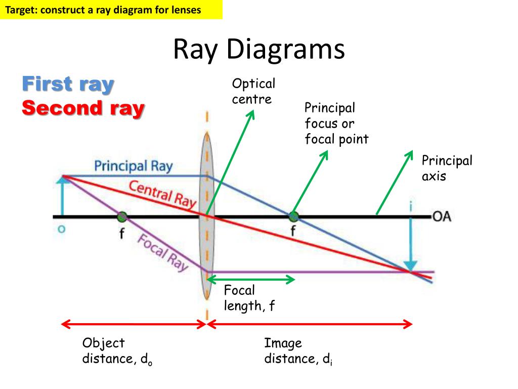
Convex lens ray diagram for when object is a distance between F and 2F from lens. Ray diagram 4 (below): The formation of a real image by a convex lens when the object O is a distance from the convex lens between F and 2F.. 4a converging lens. You construct this ray diagram 4a as exactly described for ray diagram 3.. Apart from the axis line, this is essentially a 2 ray diagram for an object ... This physics video tutorial on optics provides a basic introduction into ray diagrams. It explains how to draw ray diagrams for converging lens, diverging l... For aconvex lens, we draw the ray diagram as follows: Draw a ray from the top of the object straight through the middle of the lens. Its direction is not changed. Draw a ray from the top of the object parallel to the principal axis. It is refracted by the lens to pass through the focal point. F From the diagram we see that the image in this ... Get started drawing a ray diagram for converging lens, by drawing an optical axis. Now, put your lens on this axis somewhere, kind of in the middle to give yourself some room to work. Draw the center of the lens first, using your protractor to make sure it is perpendicular to your optical axis and that all your lines are straight.
Ray Diagrams Lenses Physics Lab Video Lesson Transcript Study Com
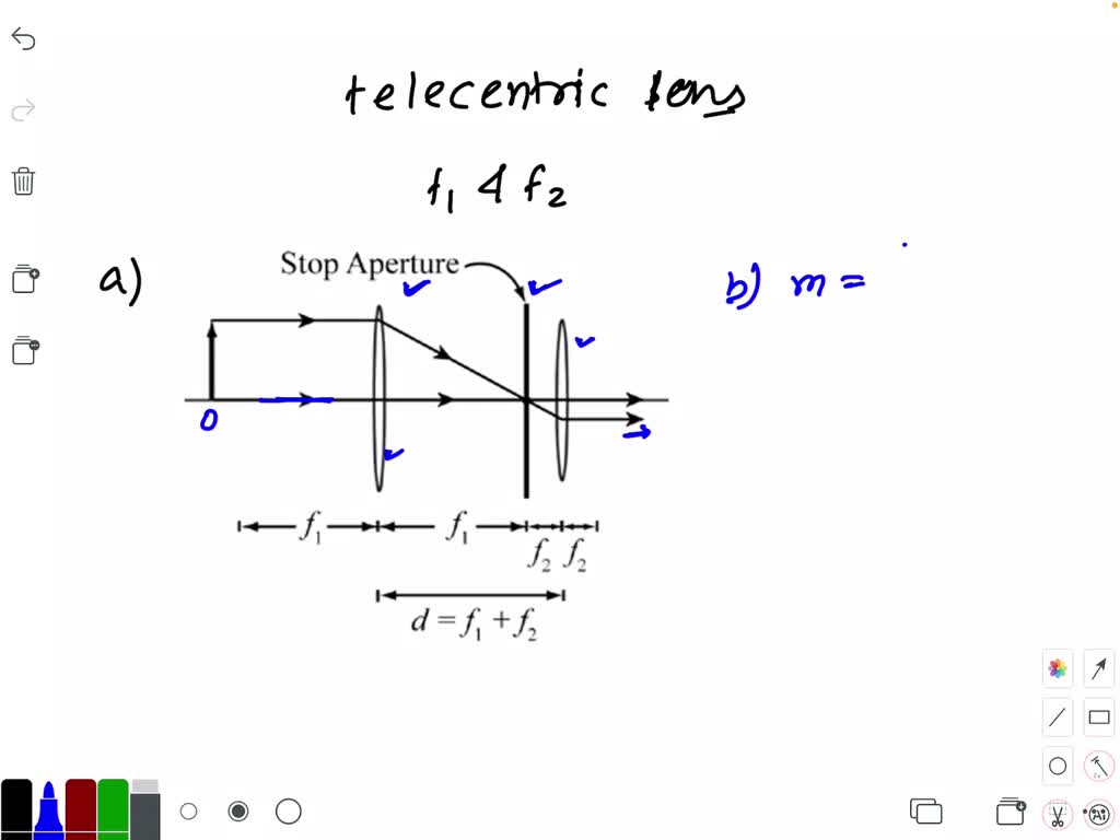
the image distance for the first lens and the separation between the two lenses. Be careful of the sign. 4. Consider again Problem 3, but for the case when d < (f 1 + f 2). Draw a ray diagram clearly indi-cating the rays from the object through the first lens to an image. Draw another diagram indicat-

Drawing Ray Diagrams For A Converging Lens The Fizzics Organization
Draw a ray diagram showing the path of rays of light when it enters with oblique incidence (i) from air into water; (ii) from water into air. Database dumps (lgdumps. Mark two or three dots on the reflected ray. 0 cm. In a ray diagram, you draw each ray as: a straight line. Symmetry - heart 8.

Prosiding Sdmtn Pdf
Two lens system – Image distance and magnification. Home Problems and Answers Optics Two lens system – Image distance and magnification . Two converging lenses, with the focal length f 1 = 10 cm and f 2 = 15 cm are placed 40 cm apart, as shown on the figure. An object is placed 60 cm in front of the first lens as show in second figure.
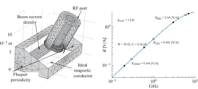
Electrodes For Beam Position Monitors For Fourth Generation Synchrotron Radiation Source Springerlink
Geometrical Construction of Ray Diagrams. A popular method of representing a train of propagating light waves involves the application of geometrical optics to determine the size and location of images formed by a lens or multi-lens system. This tutorial explores how two representative light rays can establish the parameters of an imaging scenario.
2
6. An object is placed 20 cm from a converging lens that has a focal length of 10 cm. Make a ray diagram of this situation. From the ray diagram, characterize the image. Light 142 143. Thin converging and diverging lenses Draw ray diagrams to show the formation of images in the normal eye, a short-sighted eye and a long- sighted eye. Light 143

Christophe Nicolas S Research Works Soleil Synchrotron Gif Sur Yvette And Other Places
Step-by-Step Method for Drawing Ray Diagrams. The method of drawing ray diagrams for double convex lens is described below. The description is applied to the task of drawing a ray diagram for an object located beyond the 2F point of a double convex lens. 1. Pick a point on the top of the object and draw three incident rays traveling towards the lens.

A Draw A Ray Diagram For The Following Si Clutch Prep
Convex Lenses. When an object is placed at infinity, the real image is formed at the focus. The size of the image is much smaller than that of the object. When an object is placed behind the center of curvature, the real image is formed between the center of curvature and focus. The size of the image is the same as compared to that of the object.
Switching The Orbital Angular Momentum State Of Light With Mode Sorting Assisted Coherent Laser Array System
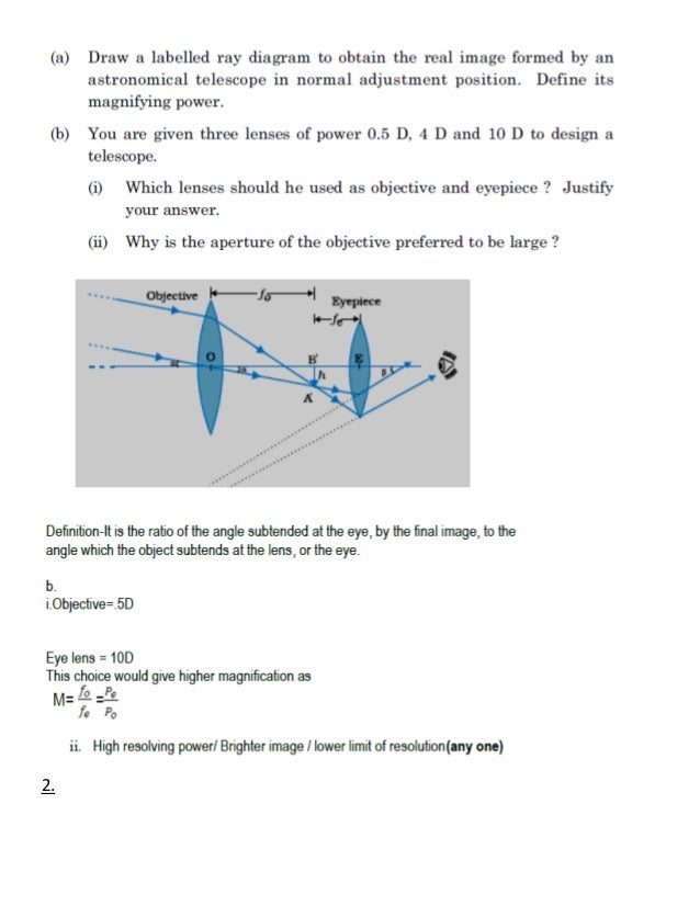
(a) Two thin convex lenses L 1 and L 2 of focal lengths f 1 and f 2, respectively, are placed coaxially in contact. An object is placed at a point beyond the focus of lens L 1.Draw a ray diagram to show the image formation by the combination and hence derive the expression for the focal length of the combined system.
Solved A Draw A Ray Diagram Of The Lens System As It Should Look At The End Of Step C6 The Setup For Forming The Image Of A Real Image Draw The Ray
A real image is an image that can be projected onto a screen. A virtual image appears to come from behind the lens. To draw a ray diagram: Draw a ray from the object to the lens that is parallel ...

Mineralogy Notes 6
The reflected ray should be drawn at the same angle from the normal - 62 degrees - but on the opposite side of the normal line. Ray 2 is thus drawn at a 62 degrees from the dashed normal line. Ray 2 is extended towards the second mirror. The process of measuring the angle of incidence and drawing the reflected ray (ray 3) is repeated.

Mineralogy Notes 6
The focal length of our lens is = _____meters B.) Draw a ray diagram of what is happening with the lens. We will assume that the rays of light coming into the lens are coming from "infinity" so that it enters the lens parallel. 2.) Playing with the object and image distances Take a moment to play with the following ray tracing applet:
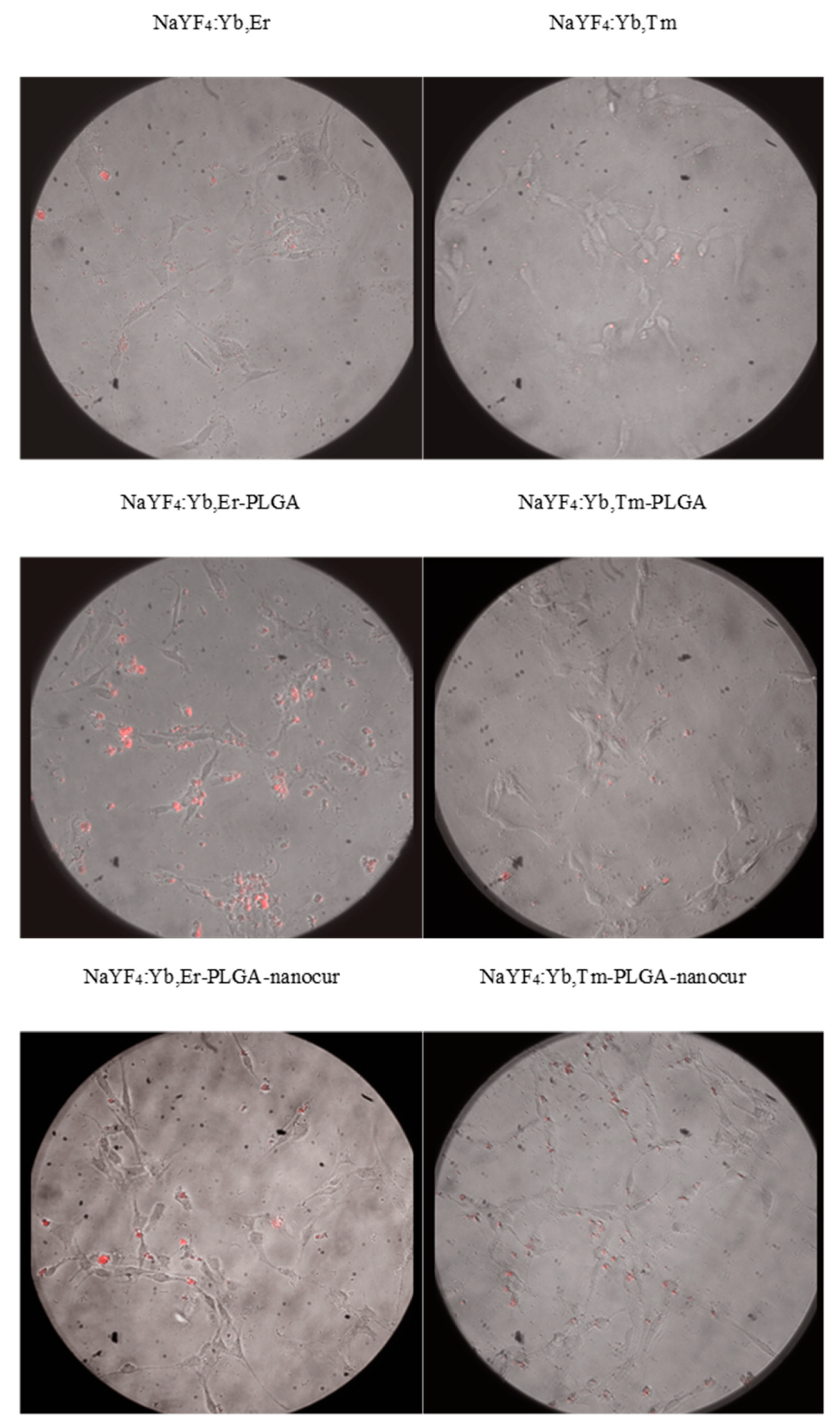
Nanomaterials Free Full Text Nanocurcumin Loaded Ucnps For Cancer Theranostics Physicochemical Properties In Vitro Toxicity And In Vivo Imaging Studies Html
Ray diagrams help us trace the path of the light for the person to view a point on the image of an object. Ray diagram uses lines with arrows to represent the incident ray and the reflected ray. It also helps us trace the direction in which the light travels.
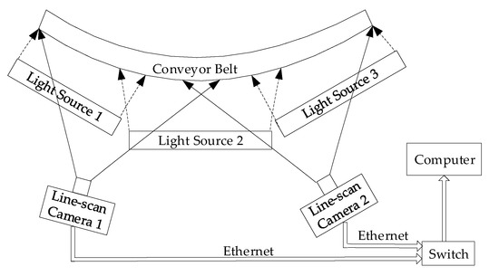
Applied Sciences Free Full Text Adaptive Multi View Image Mosaic Method For Conveyor Belt Surface Fault Online Detection Html
350 13.6 CHAPTER 13. GEOMETRICAL OPTICS - GRADE 11 Objective Lens Eyepiece Final image Figure 13.22: Compound microscope Drawing a Ray Diagram for a Two-Lens System You already have all the tools to analyze a two-lens system. Just consider one lens at a time. 1. Use ray tracing or the lens equation to find the image for the first lens.
Lenses How To Draw Ray Diagrams Teaching Resources
A thin converging lens has a focal length of 6.0 cm. An object of height 2.0 cm is located 3 cm in front of the lens. (a) Draw a ray diagram to show the image position and size. (b) Calculate the i...
2
Draw a ray diagram showing the position of the Sun that would cause sunlight to reflect into the eyes of the driver of the second car. The Sun's position directly overhead would likely reflect light into the driver's eyes, according to the law of reflection. 11. Critical Thinking Explain how diffuse
Ppt Ray Diagrams Powerpoint Presentation Free Download Id 6878954
Ray Diagrams Object N F Image Let’s check the answer by making a quick ray diagram of the situation: Ray 1: parallel then away from near focal point. Ray 2: straight through the center of the lens. Ray 3: is intended to go through far focal point but goes parallel at lens. Image is upright, diminished and virtual.
2
Ray tracing and the use of the thin lens equations produce consistent results. The thin lens equations give the most precise results, being limited only by the accuracy of the given information. Ray tracing is limited by the accuracy with which you can draw, but it is highly useful both conceptually and visually.
Solved Draw A Ray Diagram Of The Lens System As It Should Chegg Com
A ray diagram shows the path of light from an object to mirror to an eye. A ray diagram for a convex mirror shows that the image will be located at a position behind the convex mirror. Furthermore, the image will be upright, reduced in size (smaller than the object), and virtual. This is the type of information that we wish to obtain from a ray diagram.
Osa Influence Of High Numerical Aperture On Depth Of Field Enhancing Phase Mask Optimization In Localization Microscopy
Jimmy87. 660. 13. When you look up a ray diagram for a telescope you get the following: From reading my book it seems clear that the objective lens forms and image on the focal plane. This then serves as an image for the eyepiece. Since the focal length of the eyepiece at the focal length of the objective lens you get a virtual image at infinity.
2
This is the second image that this lens system is going to create and so I'll just put di. Alright, so we do the math, alright 1 over negative 10 centimeters minus 1 over 15 centimeters equals 1 over di, you solve that on the left hand side. You flip it over, you're going end up getting the di is, once you do that inversion negative 6 centimeters.

Lens Evan S Space
2

Point Of Care Tests A Review Of Advances In The Emerging Diagnostic Tools For Dengue Virus Infection Sciencedirect
1
2
Design Of A Hyperspectral Imager Using Cots Optics For Small Satellite Applications
2

Philips Bv 25 S Service Manual Pdf

How To Draw A Converging Lens Light Ray Diagram Youtube
Solved 1 Converging Lenses The Pre Lab Notes Described How Chegg Com
Physics Tutorial Refraction And The Ray Model Of Light
2
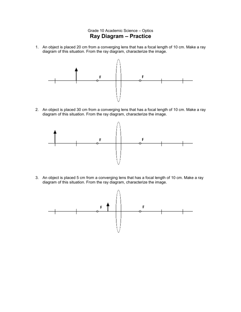
Grade 10 Academic Science Optics
Physics Special Study Material
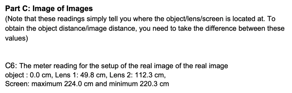
Solved Part C Image Of Images Note That These Readings Chegg Com
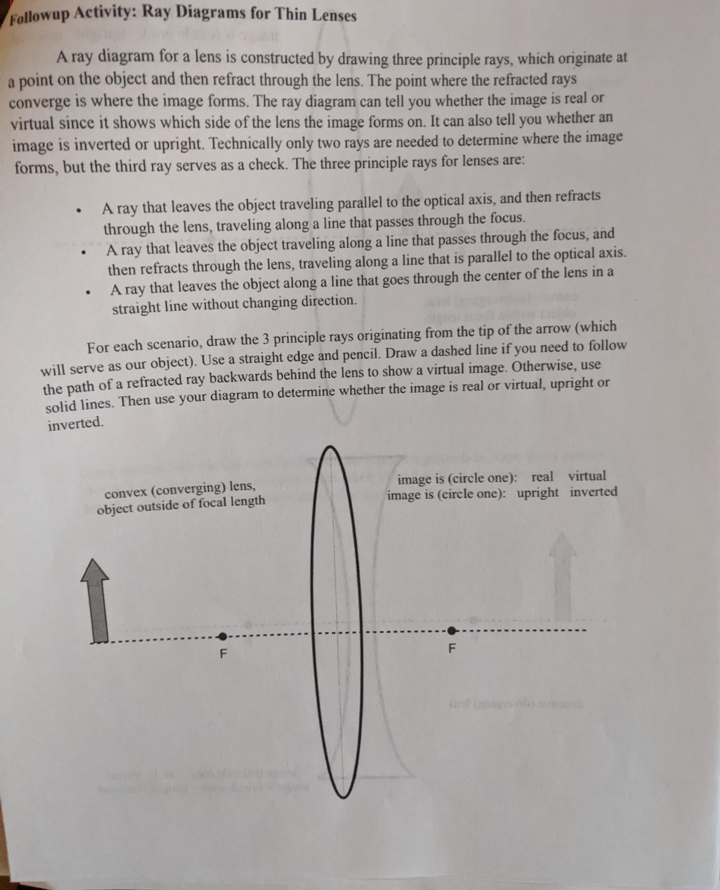
Solved Followup Activity Ray Diagrams For Thin Lenses A Ray Chegg Com

Beni B Dangi S Research Works Alabama Agricultural And Mechanical University Huntsville Aamu And Other Places
Cyberphysics Rules For Drawing Ray Diagrams
0 Response to "38 draw a ray diagram of the lens system you set up in c6"
Post a Comment