39 sump pump wiring diagram
Only a century ago, ice was hard to come by in most parts of the world. In hotter climates, you had to buy your ice from a delivery service, which imported hefty blocks from a colder climate or from an industrial refrigeration plant. The price of ice was relatively steep, but if you wanted to keep your food cold, you didn't have much choice. In the hottest parts of the world, ice was a rare luxury. In an equatorial country, you might live your whole life and never even see a piece of ice. This ... Sump Pump Wiring Diagram New Awesome Sewage Pump Wiring Diagram. Building wiring layouts reveal the approximate places as well as affiliations of receptacles, lighting, and also permanent electric solutions in a building. Interconnecting wire routes may be revealed approximately, where specific...
Sump Pump Float Switch Wiring Diagram Schematics Online. Harbor Freight Tools 1 4 Hp Submersible Sump Pump With. Pump Up Float Switch Wiring Diagram Dual Wiring Diagram. How Float Switches Work. Sump Pump With Float Water Powered Switch Drains And Pumps.
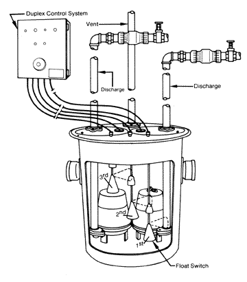
Sump pump wiring diagram
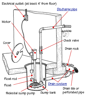
· A diagram of a centrifugal sump pump © 2009 HowStuffWorks.com A sump pump usually stands in a sump pit -- a hole with a gravel base about 2 feet Simple Sump Pump Maintenance. Septic pump wiring. Centrifugal Pump How Does It Work. Water Pump Motor Automatic and Manual Control... If it runs straight to the pressure switch it is a two wire. Submersible pump control box wiring diagram for 3 wire single phase. Shall be energized. Sump pump CONTROL-3 line diagram. No scale. Note to the designer Must be verified and detailed for each design. Figure 3-26. Sump Pump Wiring Diagram.
Sump pump wiring diagram. Wiring Diagram For Sump Pump Battery Backup Free Download. 12 Volt 20 Amp Solar Charge Controller Circuit Diagram. Automatic Ups System Wiring Circuit Diagram For Home. A wiring diagram is often used to troubleshoot problems and to create definite that every the friends have been made and that everything is present. sump pump control panel wiring diagram unique flygt pump wiring. A wiring diagram is commonly used to fix issues and to earn sure that all the connections have actually been made and that whatever is existing. Name: sump pump wiring diagram - Float Switch Circuit Diagram Unique Sump Pump Float Adjustment Diagram Elegant Float Switch Wiring. Now come to the wiring connection of three phase submersible pump. This wiring connection is too simple just like our old diagram. You can ask your question according to the three phase submersible pump wiring diagram in the below comment section. One thing more the above...
Zoeller Pump Wiring Diagram Wiring Diagram. 014955 Wm266 Zoeller Sewage Ejector Qwik Jon Pump. Wayne Vs Zoeller Sump Pump What S The Difference. 550289 3 Zoeller 840 Series Owners Manual. Sump Pump Installation Diagram Marketinglegal Com Co. Sump pump wiring. Jump to Latest Follow. Equally as important as the breaker is the wire connecting the outlet to your panel. 14-2 is too small for even a single sump pump. If you've got a 15amp breaker, chances are the wire it's attached to is small 14-2 wire. Right. So as I'm costing and planning the basement conversion I've got a few issues. One major issue is the damp proofing. Here is a rough drawing of the basement http://imgur.com/a/a5fal So the pink is the cavity membrane that I'd assume I need to install. The main part of the damp/water issue is from the very top of the image above the "cavity membrane" text. Reason being that its below ground. The left and right sides are next to our neighbours and therefore should be fine. The yellow is... I hope you guys can help me out with this... I ran a sub-panel to my basement using SER 2-3 cable. The main panel has a 2 pole 90 breaker, and the sub panel is a 125A main lug breaker. On my plan, I used the text "SER 2-3 ALUM CABLE 44 FEET", but the inspector wrote back: "subpanel must be rated with 90 amps because of the conductor is a #3 AL" Should I word my plans a little different? I am fairly certain SER number 2, 3 conductor, is acceptable for what I have. Next... The inspector asked...
Quick version: Should I be able to spin the impeller for the drain pump when the cover piece is attached? (Not the filter, the piece that restricts flow to the drain pump.) I have a Bosch SHP65T55UC/07 Series 500 SilentPlus 44dB dishwasher, which has worked fine for the last 2-3 years. It stopped draining with an error E23 (drain pump problem). I disassembled all of the drain components - checked for clogs, removed the hoses, removed and inspected the pump. I removed a piece of a dish that was... Sump Pump Wiring Diagram Best Famous Controlled Vfd Pump Wiring. 7 Wire thermostat Wiring Diagram Sample. A wiring diagram is a type of schematic which makes use of abstract pictorial symbols to show all the interconnections of components in a system. Please download these sump pump wiring diagram by using the download button, or right click selected image, then use Save Image menu. A wiring diagram is a simple visual representation in the physical connections and physical layout associated with an electrical system or circuit. Read Or Download Pump Control Panel Wiring Diagram For FREE Wiring Diagram at ACTIVEDIAGRAM.AMBITOTARCENTO.IT. booklets. There's two distinct punch designs used in Sump Pump Control Panel Wiring Diagram binding - 2:one pitch (two holes per inch) and three:1...
Sump Pump Wiring Diagram the electrician sump pump circuit wiringInstalling Electrical Circuit Wiring for a Sump Pump and providing the necessary sump pump diagram e1426717067845, image source: hdwallpaperscity.net. 326_inside, image source: www.seewaterinc.com.
Collection of sump pump wiring diagram. The float switch has two legs. The neutral wire from the panel will connect directly to the neutral wire from the pump. Pump Float Switch Wiring Diagram With Blueprint Images Diagrams. Basementsaver Wp And Hp Water Powered Backup Sump Pumps.
Elevator sump pump system elevator duplex sump pump system. The contractor shall furnish and install a Stancor System Model SE-50-TV-RPD, consisting of a Provide a NEMA 6P water tight submersible junction box with a din rail mounted wiring terminal strip.
Utilitech sump pump wiring diagram pdf format parts of a sump pump diagram free pump manual ablogro flotec sump pump replacement submersible float switch effective utilitech pool pump wiring diagram utilitech 1 1 2 hp irrigation pump ...
A microprocessor incorporates almost all of the functions of a CPU on a single integrated circuit .The first of the microprocessors emerged in the early 1970 since then they are being used for electronic calculators. Computer were for a long period constructed out of small and [medium-scale Integrated circuits containing](https://study.amaze1990.com/video-games-and-gender/) the equivalent of a few to a few hundred transistors. The integration of the whole CPU onto a single chip helped a lot and...
Sump Pump Panel. Sedona Logic - Main Wire Sheet. LeadLag Folder. On the main wire sheet are components for the six universal I/Os, one Modbus input and two relay outputs. From the BASremote main web page, all universal I/Os are configured as analog inputs except for I/O4 which is configured...
Sump pump wiring diagram new awesome sewage pump wiring diagram. Unfortunately the old switch is missing and i dont have a wiring diagram. You can also try spraying some wd 40 into the switch where the arm enters. Eventually, you will unquestionably discover a additional experience and...
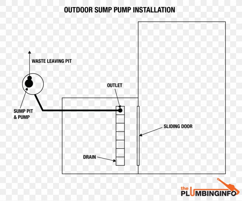
Wiring Diagram Electrical Wires Cable Schematic Sump Pump Png 1080x897px Wiring Diagram Area Cable Harness
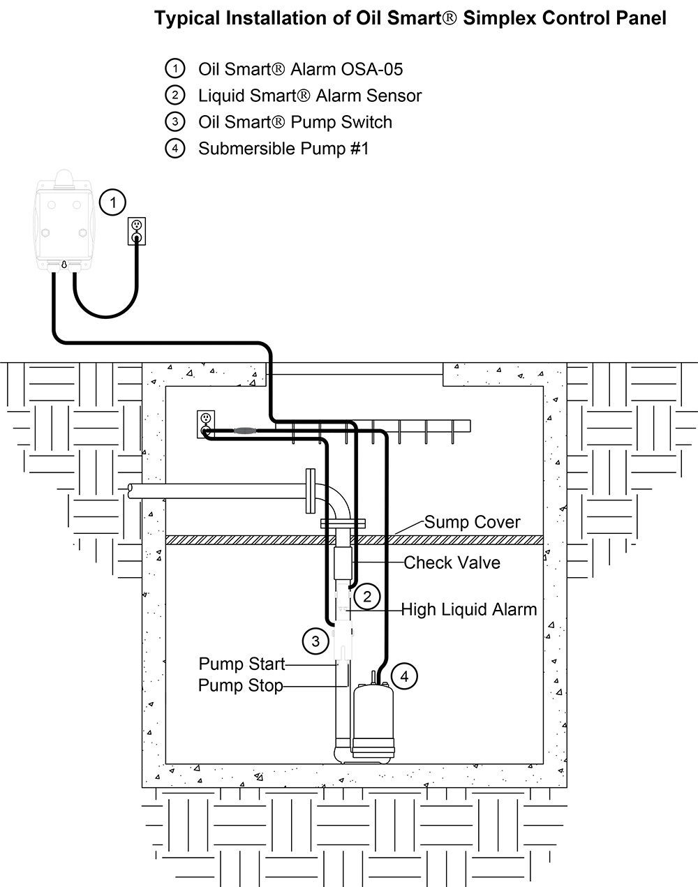
Sump Pump Control Panel Wiring Diagram. Sump Pump Diagram From Information To Installation. Sump Fill Pump Controller Circuit.

3 Phase Dol Starter Control And Power Wiring Diagram Water Pump Controller With Float Switch Youtube
Issue: Water comes in garage and basement, and appears on the floor along the west side for the entire length of the house from the garage on the north side to the basement on the south side. [Map](https://imgur.com/a/HQF5ube) Description of area: Foundation is cinder blocks on a slab from 1950 ish. Slab was finished or polished or something at some point last century. The basement is under ground on all four sides, with the garage being under ground on the west and north (basement to south) ...
After turning off the electrical connection to the sump pump unfasten the connector that holds the float to the cord then add water to the...

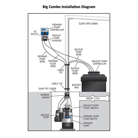
Basement Watchdog Combination Primary Pump And Backup Sump Pump Model No Dfk961 Installation Diagram Backup Sump Pump Sump Pump Sump
Sump Pump Wiring Diagram Source: usermanual.wiki. Before reading a schematic, get acquainted and understand each of the symbols. Read the particular schematic like the roadmap. I printing the schematic and highlight the signal I'm diagnosing in order to make sure Im staying on the path.
Sump Pump Wiring Diagram Best Famous Controlled Vfd Pump Wiring. Sump Pump Wiring Diagram New Awesome Sewage Pump Wiring Diagram. A Beginner s Overview of Circuit Diagrams. A very first appearance at a circuit diagram might be complicated, yet if you could read a metro map...
Sump Pump Wiring Diagram Source: usermanual.wiki. Read cabling diagrams from bad to positive in addition to redraw the signal like a straight collection. All circuits are usually the same - voltage, ground, single component, and switches.
The sump pump float switch is a part of the sump pump system which takes risk avoidance to pump when water reaches a specified point. In this article we will discuss the correct way to hard wire a float switch to a submersible pump in order to achieve automatic operation.
I'm sort of a noob at home electricity but have learned and successfully performed many other aspects of home repair, and after watching several crash course videos on home electricity, I'm confident I can safely do what needs done here. I just would like my work checked. Basically, I have a preexisting sump pump on a dedicated 20A outlet. I see two 12G wires running to the plug. One obviously supplies the power from the break box; not 100% where the other goes. But it's labelled on my bre...
This one is the first is short series on how the heat pump is wired and sequenced. This video is part of the heating and cooling series of training videos...
Hello everyone, I just fell into the rabbit hole which is residential solar setups. Within a few days, I went from wanting to buy two 100 watt panels to charge the deep-cycle batteries connected to my sump pump, to wanting to be-able to run all of my house-hold essentials entirely from solar if necessary. To do so, I plan on installing a 6.8kw system with a hybrid inverter capable of back-feeding into the utility grid, or running off-grid with batteries if necessary. I'm going to have a contac...
Sump pump float switch wiring diagram gallery. To replace the two wire pump. Pedestal Pump Switch Wiring Diagram Lotsangogi...
This Arduino Pump Tutorial shows an example of how to use a float switch, Powertail, and pump to create a sump pump system. We'll also have some wiring diagrams for a standard Arduino Uno if you're not using a RobotGeek kit.
A sump pump is a pump used to remove water that has accumulated in a water-collecting sump basin, commonly found in the basements of homes. The water may enter via the perimeter drains of a basement waterproofing system, funneling into the basin or because of rain or natural ground water...
Shall be energized. Sump pump CONTROL-3 line diagram. No scale. Note to the designer Must be verified and detailed for each design. Figure 3-26. Sump Pump Wiring Diagram.
If it runs straight to the pressure switch it is a two wire. Submersible pump control box wiring diagram for 3 wire single phase.
· A diagram of a centrifugal sump pump © 2009 HowStuffWorks.com A sump pump usually stands in a sump pit -- a hole with a gravel base about 2 feet Simple Sump Pump Maintenance. Septic pump wiring. Centrifugal Pump How Does It Work. Water Pump Motor Automatic and Manual Control...

Wiring Diagram For 220 Volt Submersible Pump Bookingritzcarlton Info In 2021 Submersible Well Pump Jet Pump Well Pump


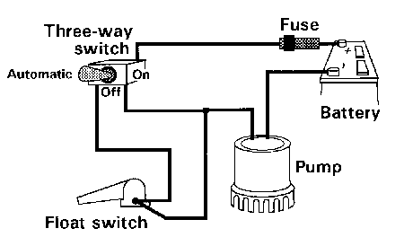

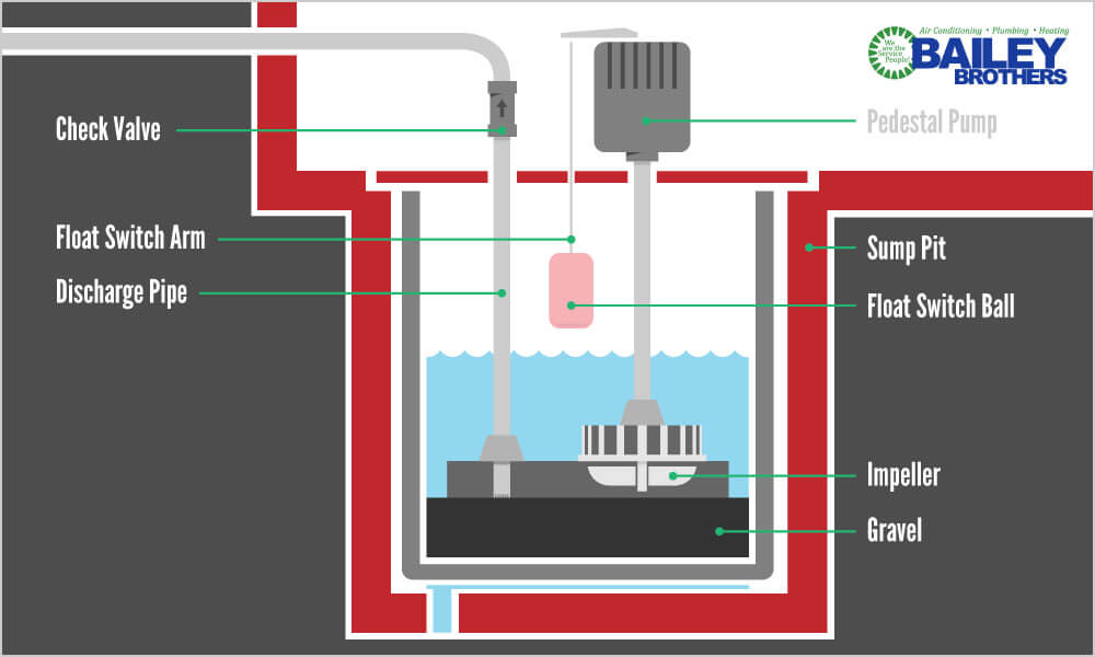






0 Response to "39 sump pump wiring diagram"
Post a Comment