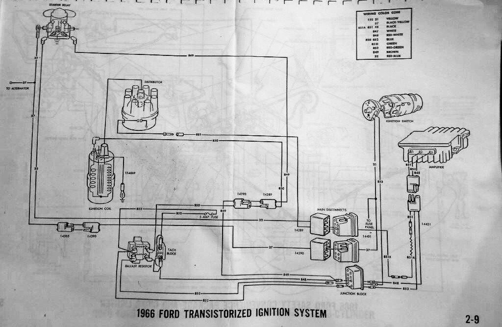
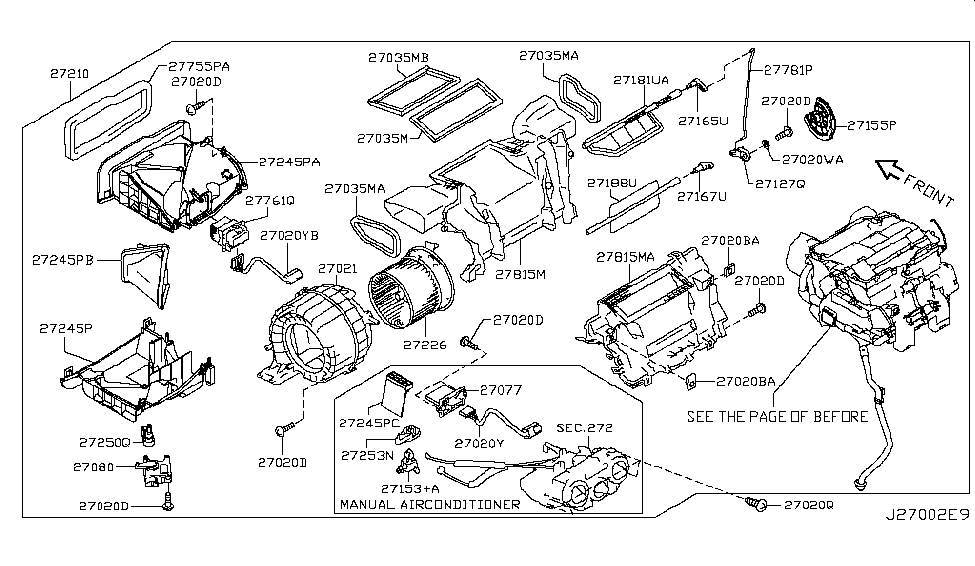
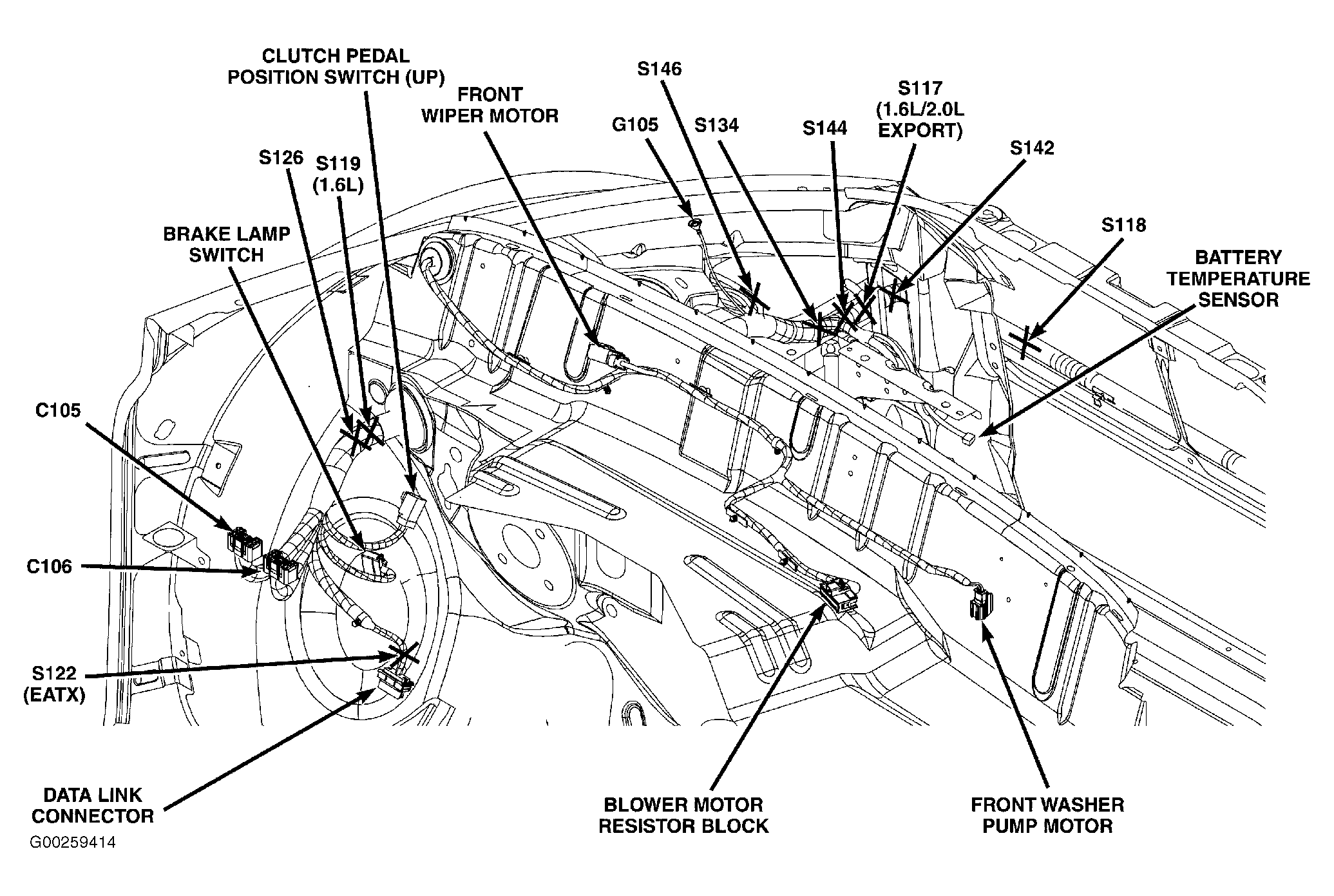
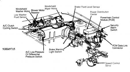
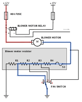
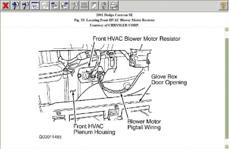
39 where is the resistor located on this diagram
29.10.2021 · So I’m guessing if I’ve corrected the jumper to 240 volts, I cld actually replace the fusible resistor with a dead short at worst, and an ordinary (non-fusible) resistor of 6.8 ohms at best. I can get a fusible resistor at 6.8 ohms and 1 watt or at 2 watts. 2 watts would risk damage to the power supply by tolerating a higher current before blowing while 1 watt might blow too often/easily. Wiring Diagram with Push Button Shifter Terminating resistor J-1939/11 data link (OEM supplied) GND + _ Shield termination Engine ECM Start enable relay Run to start signal from igntion switch 10 AMP 12 volt only manual resetting circuit breaker or 10 AMP fuse J-1587 data link 30 87 86 85 Bulkhead connector located at firewall Back side of ...
The resistor color code calculator makes it easy to identify and select resistance and tolerance values for 4, 5, and 6 band through hole resistors.

Where is the resistor located on this diagram
Where Is The Fan Resistor For The Heater Fan Located On A . Blower Motor Resistor How It Works Symptoms Problems . 2002 Dodge Ram 1500 Blower Motor Diagram Tips Electrical . Details About 4p15164p1595 Hvac Heat Blower Motor Resistor For Chevrolet Gmc Cadillac Buick . Solved 95 Volvo 850 Blower Problem Fixya And a diagram of the components inside the blower motor resistor assembly Here are a few pictures of a burned resistor wiring pigtail from a 1998 police interceptor. The blower motor did spin on speeds other than high, but spun rather slowly. Base your answers to questions 38 through 41 on the diagram and information below and on your knowledge of physics. A 15-ohm resistor, 30-ohm resistor, and an ammeter are connected as shown with a 60-volt battery. 38.If another resistor were added in parallel to the original circuit, what effect would this have on the current through resistor R1?
Where is the resistor located on this diagram. across the 5.0-ohm resistor. [Show all calculations, including the equation and substitution with units.] 24. The accompanying diagram shows two resistors connected in series to a 20.-volt battery. If the current through the 5.0-ohm resistor is 1.0 ampere, the current through the 15.0-ohm resistor is A. 1.0A B. 0.33A C. 3.0A D. 1.3A 25. Blower motor won't work. Switch and blower resistor check out ok. No power at the blower motor. I suspect the blower relay, but even though this relay is shown in my wiring diagrams for the 2002 F150 regular cab pickup, I can't find the location of this relay in my owner's manual. the relay is built into the speed resistor or motor control module ) depends if you have automative or manual heater controls. is automatic it will be motor control module and manual is the resistor module. these units are located beside the heate fan motor. the motor helps keeps the unit cool. just unbolt the module, unplug it and install new ... Joined Oct 3, 2009. ·. 7 Posts. Discussion Starter · #1 · Oct 3, 2009. Can anyone tell me where the resistor assembly is located on a 2003 CVPI? Fan motor only works on high. Bought the new assembly and told it was up under the passenger side dash near firewall but can't locate it.
It seems this is a hot topic.....The blower motor resistor must go out on all of these vans. I am just wondering where it is located in my 04'? Anyone know? Anyone have a diagram?? Thanks!!!!!! A resistor appears on this board, the fifth component counting up from the bottom, located in the middle-right area of the board. A view of this board’s underside reveals the copper “traces” connecting components together, as well as the silver-colored deposits … I need a diagram for the location of the blower motor resistor on a jeep renegade. 50k manual. 2017. And I need to speak - Answered by a verified Jeep Mechanic This is the Blower Motor Resistor that has gone bad. The sure sign is only Off and High working. This is located near the Blower Motor and is easily accessed, removed and replaced. Autozone.com, Part #JA1504 for around $25. This has a photo of the part and a Job View Diagram to help you in your endeavors.
1.The diagram below represents a lamp, a 10-volt battery, and a length of nichrome wire connected in series. ... Where should an ammeter be located to correctly ... resistor is the same as the potential difference across the 3-ohm resistor. B)The potential difference across the 6-ohm resistor is twice as great as the potential difference across ... Re: 1988 OMC Ballist resistor location?? It shouldn't matter. If you look at the circuit diagram, you'll see that the A+ (thru the ballast "resistor") goes directly to the "plus" side of the coil. The ESA (output) is essentially in parallel with the points/condenser. Joined Dec 13, 2008. ·. 662 Posts. Discussion Starter · #1 · Jan 10, 2010 (Edited) I finally got around to changing my blower motor resistor block in my truck today. It was a balmy 17 ° out so I thought what the heck. The hardest part of the job was to locate where the darn thing was. It is located back behind the glove box toward the top. Wiring diagrams show how the wires are connected and where they should located in the actual device, as well as the physical connections between all the components. How is a Wiring Diagram Different from a Pictorial Diagram? Unlike a pictorial diagram, a wiring diagram uses abstract or simplified shapes and lines to show components.
21.7.2021 · Electrical Diagram Software You can use the built-in electrical symbols to make well-crafted electrical diagrams in minutes. So it has become quite easy to create schematics, wiring diagrams, circuit diagrams and other electraical diagrams.Select from switches, relays, transmission paths, semiconductors, power sources, batteries, integrated circuit components, etc.
Installing the Mopar electronic ignition requires a distributor with the magnetic pickup, and one more wire to the ballast resistor. This wiring diagram is for the 1980 and later four pin ignition module. If you have an ignition harness with five wires, just don't connect the dark green wire that would go to pin 3.
Citroen C3 A51 model 2009-on Blower heater resistor location diagram. This is the heater resistor diagram for the post 2009 cars. Number 5 is the heater resistor on an A51 C3 (post 2009 models with the new shape) It doesn't look very easy to get to. Top.
Aug 01, 2021 · In the 2008-2011 Ford Escape, the resistor is located behind the glove box on top of the HVAC unit air duct. It's held by two screws and is easy to replace. See the photo. In the 2008-2011 Ford F150, the blower motor resistor is also located behind the glove box, but is installed on the right side of the plastic air duct.
To read and understand an electronic diagram or electronic schematic, the basic symbols and conventions must be understood. EO 1.1 IDENTIFY the symbols used on engineering electronic block diagrams, prints, and schematics, for the following components. a. Fixed resistor o. Fuse b. Variable resistor p. Plug c. Tapped resistor q. Headset d.
Answer: 2 📌📌📌 question Where is the resistor located on the diagram? - the answers to estudyassistant.com
Wiring diagram for 2001 Dakota and Durango Blower Motor Resistor. With this kit available from Napa/Dorman, make sure to use the proper crimping tool that cr...
•On 4700 models, the terminating resistor is located behind the glove box. See Fig. 6. 3.1 Remove the 120-ohm terminating resistor from the J1939 backbone connector, located behind the instrument panel. 3.2 Install the 120-ohm terminating resistor to the male connector on the A06-87079-108 harness for
On the manual system there's a component labeled "Blower Motor Resistor" under a 4-pin connector plugged into the [EDIT -] driver's side of the HVAC plenum just below the motor itself (about 7 o'clock position relative to the motor). FWIW the WSM calls for removal of the accelerator pedal to R&R that component.
Ac fan only blowing on high
The resistor is located inside the motor. there are 3 bolts on the back of the motor. Just remove the bolts and take the back cover off. Then in the middle of the motor there is a little clamp holding the motor in place. When you remove the motor itself, the resistor is in the middle. The one that blew on my car was the 470uf 50v.
The other is the resistor wire as described by Everett which heats up and drops the voltage coming from the ignition switch so the points don't wear out prematurely. My understanding is the change in wire gauge/type at the bulk head connector is because you don't want the heat buildup in the resistance wire on the inside of the car.
According to the diagram sent by jnells (thank again) the plug to the resistor is always hot since I have the automatic system, not the manual. I pulled the HVAC ctrl, HVAC blower fuses and the HVAC Blower high relay on the BCM and still have 12v at the blower fan plug. I also pulled the two IBCM fuses under the hood and still have 12v.
The resistor color code calculator makes it easy to identify and select resistance and tolerance values for 4, 5, and 6 band through hole resistors.
Where is the resistor located on the diagram? 2 See answers jacobadamcartep5y5ur jacobadamcartep5y5ur The answer is B hope this helps the switch is point A Okay thank you one more. In this diagram, if a light bulb is placed at D and B is closed(as shown), what will happen? The light bulb will be off The light bulb will be dimmer than normal
Where is the blower motor resistor located on a 2000 Chevy Malibu and is it hard to replace? Is there a diagram? - Answered by a verified Chevy Mechanic. We use cookies to give you the best possible experience on our website.
Question: Refer to the circuit in the diagram. If the battery has an emf of 9.4V, what is the current in the resistor R3? Ri=22 w R=22 w Rg=32 w w Rz=202 w Rs=22 The electric field in a given location points along the +x axis. This means that E +X at that location, the potential is negative. at that location, the potential decreases as one ...
Oct 18, 2019 · Answer: 3 📌📌📌 question Refer to the following diagram to answer this question where is the resistor located on this diagram a d b c - the answers to estudyassistant.com
The above figure represents domestic circuit diagram. The electric power that we receive in our houses is by the main supply, commonly called mains. It is supplied by either overhead cables or by underground cables. There are 3 types of wires in domestic circuits and these are …
But I can't find any diagrams that show where it's located or how to replace it (I've checked the forums here, but couldn't glean enough to help). Does anyone have experience replacing the blower motor resistor on a 90-92 LS400, and if so, can you explain the procedure? Would appreciate a diagram, too, if someone is kind enough to post one here.
construction diagram: A diagram that shows the physical arrangement of parts, such as wiring, buses, resistor units, etc. Example: A diagram showing the arrangement of grids and terminals in a grid-type resistor. control sequence diagram: A portrayal of the contact positions or connections that are made for each successive step of the control ...
Base your answers to questions 38 through 41 on the diagram and information below and on your knowledge of physics. A 15-ohm resistor, 30-ohm resistor, and an ammeter are connected as shown with a 60-volt battery. 38.If another resistor were added in parallel to the original circuit, what effect would this have on the current through resistor R1?
And a diagram of the components inside the blower motor resistor assembly Here are a few pictures of a burned resistor wiring pigtail from a 1998 police interceptor. The blower motor did spin on speeds other than high, but spun rather slowly.
Where Is The Fan Resistor For The Heater Fan Located On A . Blower Motor Resistor How It Works Symptoms Problems . 2002 Dodge Ram 1500 Blower Motor Diagram Tips Electrical . Details About 4p15164p1595 Hvac Heat Blower Motor Resistor For Chevrolet Gmc Cadillac Buick . Solved 95 Volvo 850 Blower Problem Fixya













0 Response to "39 where is the resistor located on this diagram"
Post a Comment