41 draw the free-body diagram for the cantilevered beam. a is the a fixed support.
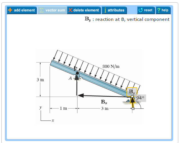
Draw the free-body diagram for the cantilevered beam. A is the a fixed support Draw the vectors starting at the black dots. The location and orientation of the vectors will be graded. The length of the vectors will not be graded. Double-click on the black dot to indicate the direction of the moment. Transcribed image text: Part A Draw the free-body diagram for the cantilevered beam. A is the a fixed support Draw the vectors starting at the black dots.
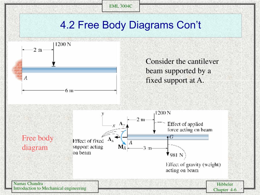
1. Draw Free Body Diagram 2. Apply Equilibrium Example: Cantilevered Flag Figure M4.3-8 Geometry and free body diagram of cantilevered flag z x ~ ~ ~ • x z m = mass/unit length mg H A V A M A f f L L FREE BODY DIAGRAM:
Draw the free-body diagram for the cantilevered beam. a is the a fixed support.
Part A Draw the free-body diagram for the cantilevered beam. Subject: Civil Engineering Price: 3.85 Bought 3. Share With. Part A Draw the free-body diagram for the cantilevered beam. A is the a fixed support. Draw the vectors starting at the black dots. The location and orientation of the vectors will be graded. The length of the vectors will ... Example 6. Example 6:For the cantilever beam and loading shown, determine the reactions at the support. Solution:We begin our analysis by first drawing the free-body diagram of the beam. Once we have the unknown reaction loads identified, we solve for them using the equilibrium equations. Free-Body Diagram of Beam:The beam is fixed at point A. Therefore, there are two reaction forces and one reaction moment at this point as shown below. Draw the shearing force and bending moment diagrams for the cantilever beam supporting a concentrated load at the free end, as shown in ...
Draw the free-body diagram for the cantilevered beam. a is the a fixed support.. Sep 24, 2017 · Draw the free body diagram for the cantilevered beam a is the a fixed support. Draw the vectors starting at the black dots. Our first step is to draw a free body diagram like so. Determine the components of the support reactions at the fixed support a on the cantilevered beam. A y 4knd 0 m a. section of a beam : draw a free-body diagram that expose these forces and then compute the forces using equilibrium equations. The goal of the beam analysis -determine the shear force V and the bending moment M at every cross section of the beam. To derive the expressions for V and M in terms of the distance x measured along the beam. Nov 11, 2021 · For each beam shown draw the free body diagram and discuss the support reactions present. The cantilever is a beam which has one end free and the other is fixed. The following is the process for determining the reaction at the wall for a cantilever beam . Oct 31, 2015 · The location and orientation of the vectors will be graded. Draw the free body diagram for the cantilevered beam a is the a fixed support the above diagrams which show the complete system of applied and reactive forces acting on a body are called free body diagrams. A is the a fixed support draw the vectors starting at the black dots. Draw the fbd of the bracket shown. The location and orientation of the vectors will be graded.
roblem 5.1 Part A Draw the free-body diagram for the cantilevered beam. A is the a fixed support. Draw the vectors starting at the black dots. beam diagrams and formulas 3-213 table 3-23 shears, moments and deflections 1. simple beam-uniformly distributed load ... cantilevered beam- load increasing uniformly to fixed end ... beam fixed at one end, free to deflect vertically but not rotate at other - uniformly distributed load total equlv. uniform load ..... Draw the Free Body Diagrams. Learning Objectives 1. To be able to explain the equilibrium of Rigid Body Systems ... A Cantilever has to be fixed to support a load. Question 1. What is the difference between a Rigid Body and a Particle Question 2: Explain the Difference between a ... Beam Free Body Diagram. Actual Structure - A Truss Free Body ... directly on the diagram. Pertinent dimensions may also be represented for convenience. Note, however, that the free-body diagram serves the purpose of focusing accurate attention on the action of the external forces; therefore, the diagram should not be cluttered with excessive information. Force arrows
As a general rule, if a support prevents translation of a body in a given direction, ... Draw the free body diagram: R ... A cantilever beam is loaded as shown. Determine all reactions at support A. 5 kN/m 2 m 2 m 1 m A 20 kN 3 4 15 kNm EXAMPLE 3 . Find the reactions at the supports for a simple beam as shown in the diagram. Weight of the beam is negligible. Figure: Concepts involved • Static Equilibrium equations Procedure Step 1: Draw the free body diagram for the beam. Step 2: Apply equilibrium equations In X direction ∑ F X = 0 ⇒ R AX = 0 In Y Direction ∑ FY = 0 Do not draw free-body diagram forces on top of your problem drawing — the body needs ... The cantilevered beam is embedded into a fixed vertical wall at . Show me the final answer↓. Our first step is to draw a free body diagram like so: Remember that since the beam is attached at a fixed support, a moment is also created at A. Let us now write an equilibrium equation for the x-axis forces. → + Σ F x = 0; \rightarrow^+ \Sigma F_x=0; →+ ΣF x. .
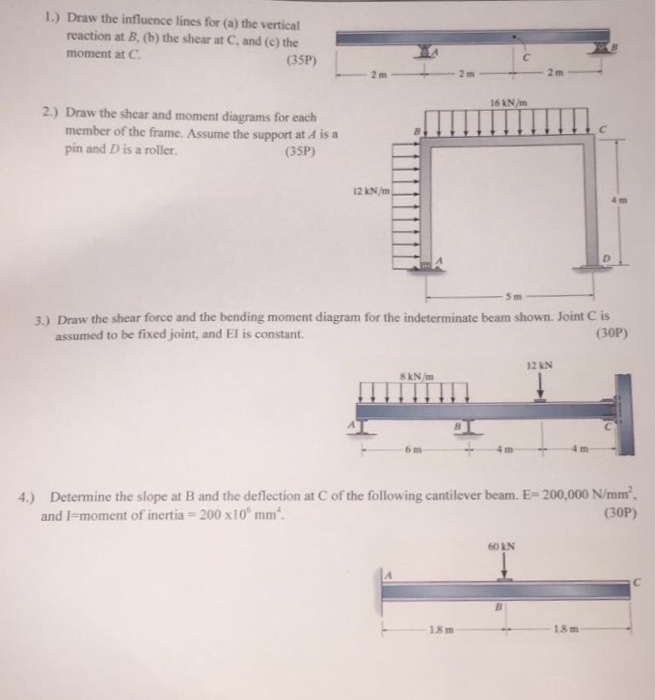
Get Answer Draw The Influence Lines For A The Vertical Reaction At B B Transtutors
Consider the loading on the propped-cantilevered beam shown below. a) List all of the geometric boundary conditions for this problem. Make a sketch of the expected deflection shape of the beam, paying close attention to the geometric boundary conditions of the problem. b) Equilibrium. Draw a free body diagram of the entire beam and derive the

For The Cantilever Beam And Loading Shown A Evaluate Beam Reactions Derive Equations For The Shear Force V And The Bending Moment M For Any Location In The Beam Place The Origin
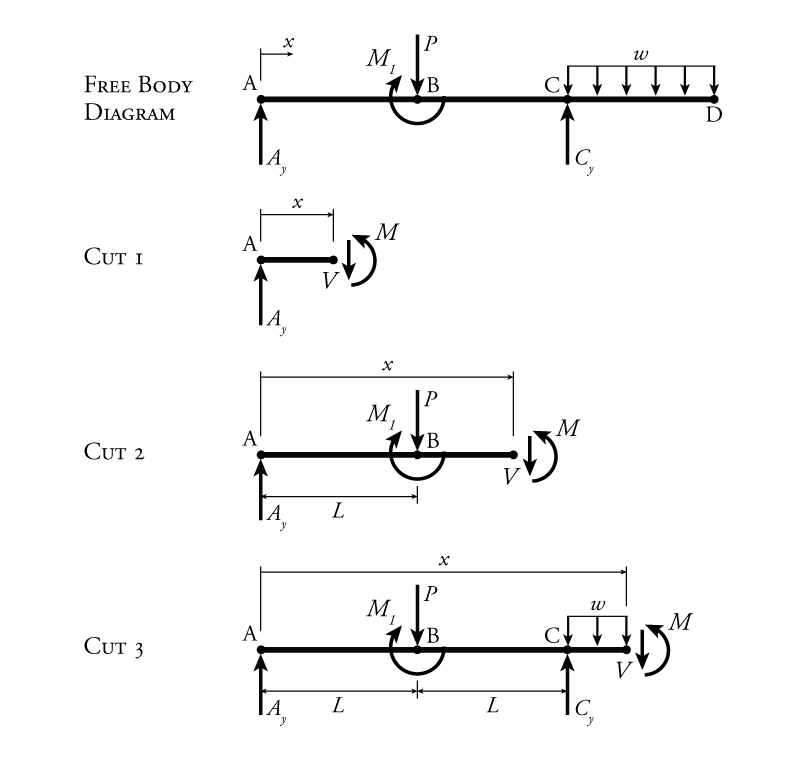
Draw free body diagram for the segment of the beam. Show S & M at the cut section, 5. Write the equilibrium equations, obtainable from the free body diagram, 6. Solve the equilibrium equations for the Shear Force S and the Bending Moment M, 7. Plot the expressions for S and M for the segment. It is desirable to draw the shear force diagram ...
Beam And It S Type Beam Beam Is A Structural Member Of Which One Dimension Is Considerably Larger Than Other Two Dimension And Accociated With Loads Suorts Tyes Of Beam Simply Supported Beam If The Ends Of A Beam Are Made To Rest Freely On Supports
A short video to show how to form an imaginary cut and draw a free body diagram of a simply supported beam with a point load.Related videos:Reactions of a Si...
Solved Problem 5 1 Vectors Fa Bx By Part A Draw The Chegg Com
Apr 06, 2020 · Draw the free body diagram for the cantilevered beam. Draw the vectors starting at the black dots. Draw the vectors starting at the black dots. To change the direction click on the dot one more time. Double click on the back dot to indicate the direction of the moment. Fa bx by part a draw the free body diagram for the cantilevered beam.
Shear Force Bending Moment Diagram Of Cantilever Beam Examples Engineering Intro
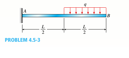
As we can see here that one end of the beam AB is fixed at one end i.e. at A and other end is free i.e. at end B. Therefore, we can say that we have one cantilever beam here and we will have to find the method to draw shear force and bending moment diagram when cantilever beam will be loaded with uniformly distributed load.
Solved Problem 5 1 Vectors Fa Bx By Part A Draw The Chegg Com
(which has an overhang) and a beam fixed (or restrained) at both ends, respectively. Cantilever beams and simple beams have two reactions (two forces or one force and a couple) and these reactions can be obtained from a free-body diagram of the beam by applying the equations of equilibrium. Such beams are said to be statically
Solved Draw A Free Body Diagram Of The Cantilevered Beam Chegg Com
FREE-BODY DIAGRAMS (Section 5.2) 2. Show all the external forces and couple moments. These typically include: a) applied loads, b) support reactions, and, c) the weight of the body. Idealized model Free-body diagram (FBD) 1. Draw an outlined shape. Imagine the body to be isolated or cut "free" from its constraints and draw its outlined shape.

Cantilever Beam Shear Force And Bending Moment Diagram With Triangular Load Youtube
• Create a free-body diagram for the complete frame and solve for the support reactions. • Define a free-body diagram for member BCD. The force exerted by the link DE has a known line of action but unknown magnitude. It is determined by summing moments about C. • With the force on the link DE known, the sum of forces in the x and y directions
Solved Question 2 A Cantilever Beam Is Loaded And Propped As Shown In Figure Q2 A Determine The Support Reactions For This Beam 4 Marks B Dr Course Hero
Feb 27, 2016 · Our first step is to draw a free body diagram like so. The cantilever is a beam which has one end free and the other is fixed. Determine the components of the support reactions at the fixed support a on the cantilevered. Shear Force And Bending Moment Diagrams Wikiversity Solved Draw A Free Body Diagram Of The Cantilevered Beam Hibbeler Chapter5
Hibbeler Chapter5
... http://www.patreon.com/daxterbels Determine the components of the support reactions at the fixed support A on the cantilevered beam.

Shear Force And Bending Moment Diagram For Cantilever Beam With Udl Mechanical Engineering Concepts And Principles
beam diagrams and formulas by waterman 55 1. simple beam-uniformly distributed load ... 22. cantilever beam-concentrated load at free end. 23. beam fixed at one end, free to deflect vertically but not rotate at other-concentrated load at deflected end 24. beam overhanging one support-uniformly distributed load. 25. beam overhanging one support ...

4 5 Shear Force And Bending Moment Of Cantilever Beams Strength Of Materials Book
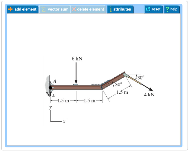
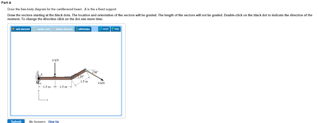
Draw the free-body diagram for the cantilevered beam. A is the a fixed support. Draw the vectors starting at the black dots. The location and orientation of the vectors will be graded. The length of the vectors will not be graded. Double-click on the back dot to indicate the direction of the moment. To change the direction click on the dot one more time.
Answered Draw The Shear Force Diagram Bending Bartleby
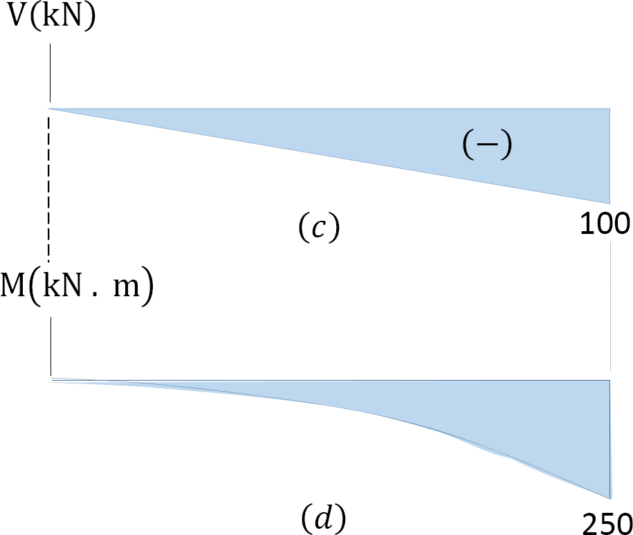
cross section located 0.5 m from the fixed support of the cantilever beam ... Draw the shear-force and bending-moment diagrams for this beam.

Civil Engineering Mechanics Cantilever Beam Shear Force And Bending Moment Diagram Practice Problem Facebook
Part A Draw the free-body diagram for the cantilevered beam. A is the a fixed support. Draw the vectors starting at the black dots. The location and orientation of the vectors will be graded. The length of the vectors will not be graded. Double-click on the black dot to indicate the direction of the moment. To change the direction click on the dot one more time. Part B. Draw the free-body diagram for the beam. A is a rocker and B is a pin. Draw the vectors starting at the black dots.
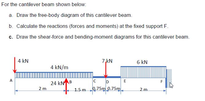
Solved For The Cantilever Beam Shown Below A Draw The Chegg Com
- Consider the simply supported cantilever beam that is subjected to a uniformly distributed load w w A B L Figure 35. 11 ... • Consider beam with fixed support at A and roller support at B. • From free-body diagram, note that there are four ... • Drawing the free-body diagram of a portion of the beam (AC) as shown in Fig. 39, we write A A
4 3 Determinate Beam Analysis Learn About Structures
what has to draw free by diagrams for problems. 10 11 12 and 13. So problem 10. We never beam. Um, this cantilevered from this end as a cable attached to it ...
Solved Part A Draw The Free Body Diagram For The Chegg Com
AMERICAN FOREST & PAPER ASSOCIATION Figures 1 through 32 provide a series of shear and moment diagrams with accompanying formulas for design of beams under various static loading
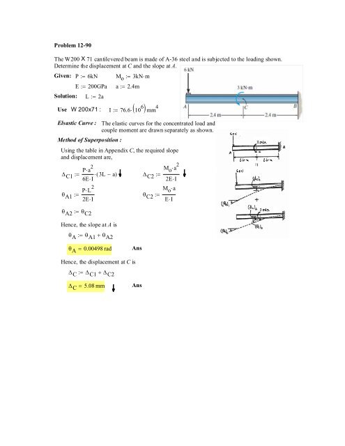
Problem 12 90 The W200 X 71 Cantilevered Beam Is Made Of A 36
Free body diagrams may not seem necessary in the relatively simple current applications, but as problems become more complex, their usefulness increases. The following is the process for determining the reaction at the wall for a cantilever beam.
Ppt Chapter 4 Equilibrium Powerpoint Presentation Free Download Id 307417
https://goo.gl/P5AUbb for more FREE video tutorials covering Engineering Mechanics (Statics & Dynamics)The key objective of this video is to consider support...

Shear And Bending Moment Diagrams Learning Goal To Determine The Reactive Forces And Moments Acting On Homeworklib
Using the free-body diagram of the portion AC of the beam (Fig. 8.8), where C is located at a distance x from end A, we find (8.7) Substituting for M into Eq.. (8.4) and multiplying both members by the constant El, we write d 29' El Integrating in F, we obtain The deflection and slope at A are obtained by letting — O in Eqs. (8.11) and (8.9).
What Are Free Body Diagrams
Draw the shearing force and bending moment diagrams for the cantilever beam supporting a concentrated load at the free end, as shown in ...

Shear Force And Bending Moment Diagram For Cantilever Beam With Point Load Mechanical Engineering Concepts And Principles
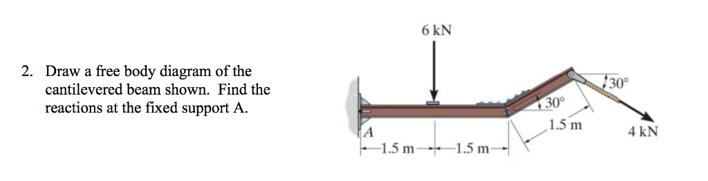
Example 6. Example 6:For the cantilever beam and loading shown, determine the reactions at the support. Solution:We begin our analysis by first drawing the free-body diagram of the beam. Once we have the unknown reaction loads identified, we solve for them using the equilibrium equations. Free-Body Diagram of Beam:The beam is fixed at point A. Therefore, there are two reaction forces and one reaction moment at this point as shown below.

Question 1 A Abeam Has A Fixed Support At A And Roller Supports At D And E As Shown In Fig Q La Below Internal Homeworklib
Part A Draw the free-body diagram for the cantilevered beam. Subject: Civil Engineering Price: 3.85 Bought 3. Share With. Part A Draw the free-body diagram for the cantilevered beam. A is the a fixed support. Draw the vectors starting at the black dots. The location and orientation of the vectors will be graded. The length of the vectors will ...
4 Shear Forces And Bending Moments
4 4 Relation Among Distributed Load Shearing Force And Bending Moment Engineering Libretexts
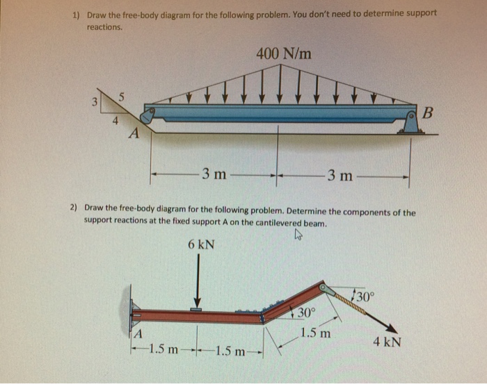
Solved Draw The Free Body Diagram For The Following Problem Chegg Com
Example 2
Draw The Shear And Moment Diagrams For The Cantilever Beam
Solved Equilibrium Of A Rigid Body Engineering Mechanics Statics And Dynamics 14th Physics Numerade

Draw The Moment Diagram For The Cantilevered Beam Study Com
Faculty Kfupm Edu Sa
Ncet Co In

The Overhanging Beam Is Supported By A Pin At A And The Two Force Strut Bc Draw A Free Body Diagram And Determine The Horizontal And Vertical Components Of Reaction At A And B

A Cantilever Beam Ab Is Subjected To Two Concentrated Load As Shown In Figure Ex 2 Determine A Reactions At Fixed Support A And B Draw The Shear Force And Bending Moment
Chapter 4 Internal Forces In Beams And Frames In Structural Analysis On Manifold Tupress
1 4 Internal Forces In Beams And Frames Engineering Libretexts

Solved Draw The Shear And Moment Diagrams For The Loaded Cantilever Beam 1 Answer Transtutors

Pdf Shear Forces And Bending Moments Md Shahin Alam Academia Edu
Solved Beam Abc Has A Fixed Support At A And A Roller Support At C A Frictionless Internal Hinge At B Links The Two Segments Of The Beam Draw The Course
Solved Equilibrium Of A Rigid Body Engineering Mechanics Statics And Dynamics 14th Physics Numerade

Solved Draw The Shear And Moment Diagrams For The Loaded Cantilever Beam 1 Answer Transtutors
0 Response to "41 draw the free-body diagram for the cantilevered beam. a is the a fixed support."
Post a Comment