41 mcdonnell miller low water cutoff wiring diagram
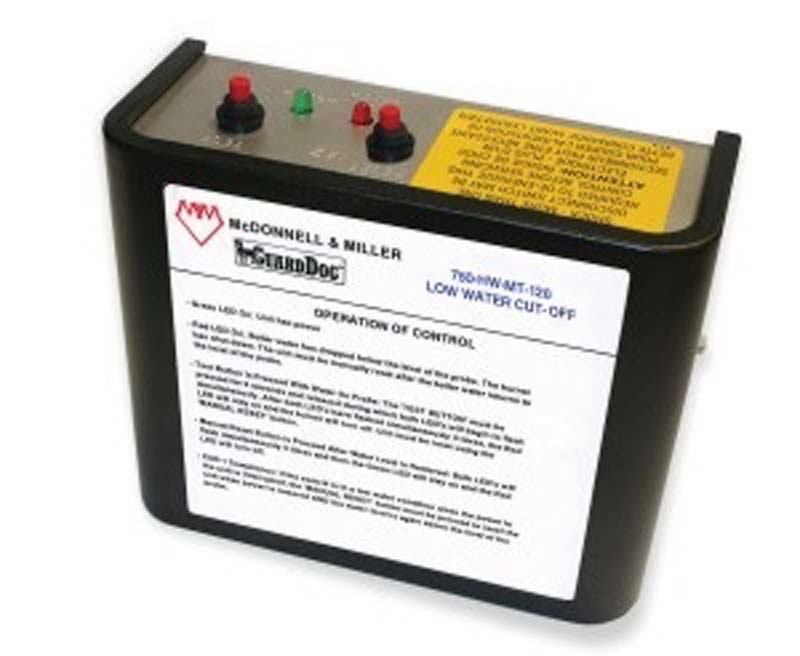
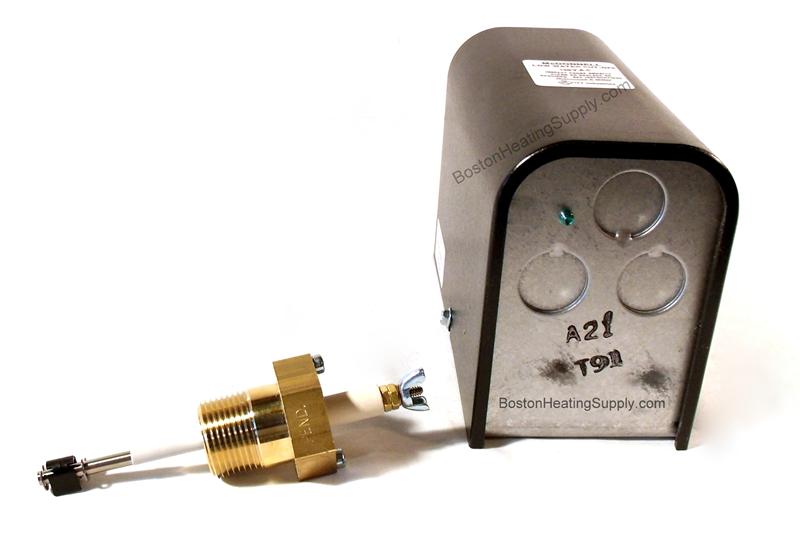
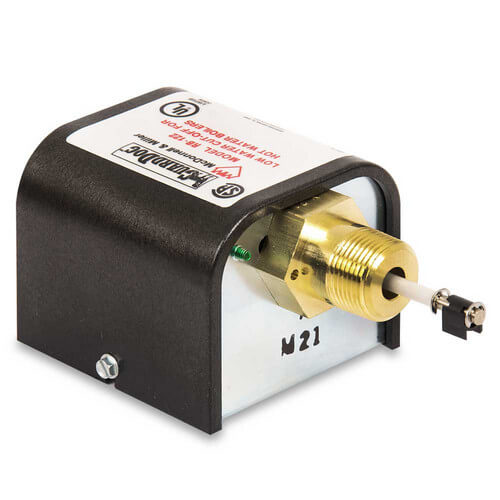
McDonnell & Miller Installation & Maintenance Instructions MM-202(N) 2 SPECIFICATIONS ... • This low water cut-off must be installed in series with all other limit and operating controls installed on the boiler. After installation, check for proper operation of all of the limit and operating controls, before leaving ... Wiring Diagram Legends ... Mcdonnell & Miller - RBE, Electronic, 24V Low Water Cut-Off - (Water) - Features & Benefits: Specifically designed to shut off the Burner if there is a unsafe water loss For residential applications Compact size Easy to install and wire Automatic reset feature resumes operation after a power outage when water is on probe Green power.
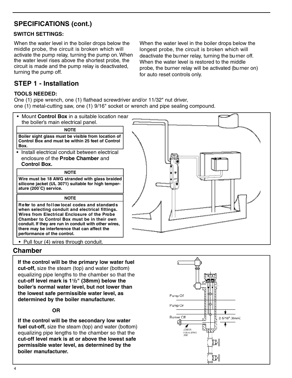
STEP 2 - Electrical Installation. Feeder Model. LWCO Model. Diagram Number. Page. WFE-24. PS-802 with burner wiring harness.8 pages

Mcdonnell miller low water cutoff wiring diagram
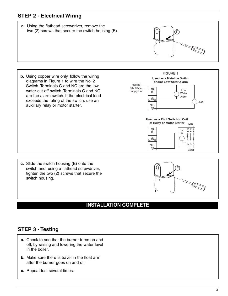
This low water cut-off must be installed in series with all other limit and operating ... McDonnell & Miller ... Some boiler wiring diagrams indicate.8 pages (1) screw that secures the low water cut-offs switch housing (Y). BB b. Using a flathead screwdriver, remove the two (2) screws that secure the feeder cover(BB). For 67 Low Water Cut-Off Installed with McDonnell & Miller Series 101-A Water-Feeder For the 120V Burner/120V Feeder setups. BURNER 120 VAC SUPPLY 12 34 N H 101A 69 c. Using a wire nut ... Low Water Cut Off Wiring Diagram | Manual E-Books – Mcdonnell Miller Low Water Cutoff Wiring Diagram. Wiring Diagram comes with a number of easy to follow Wiring Diagram Directions. It really is supposed to aid all of the typical person in developing a proper method. These instructions will probably be easy to grasp and apply.
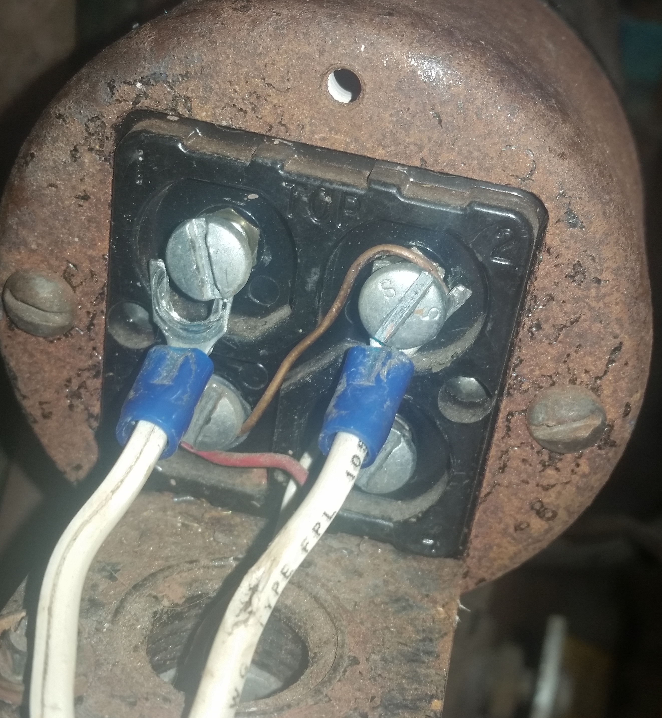
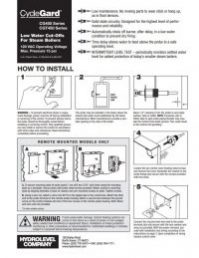
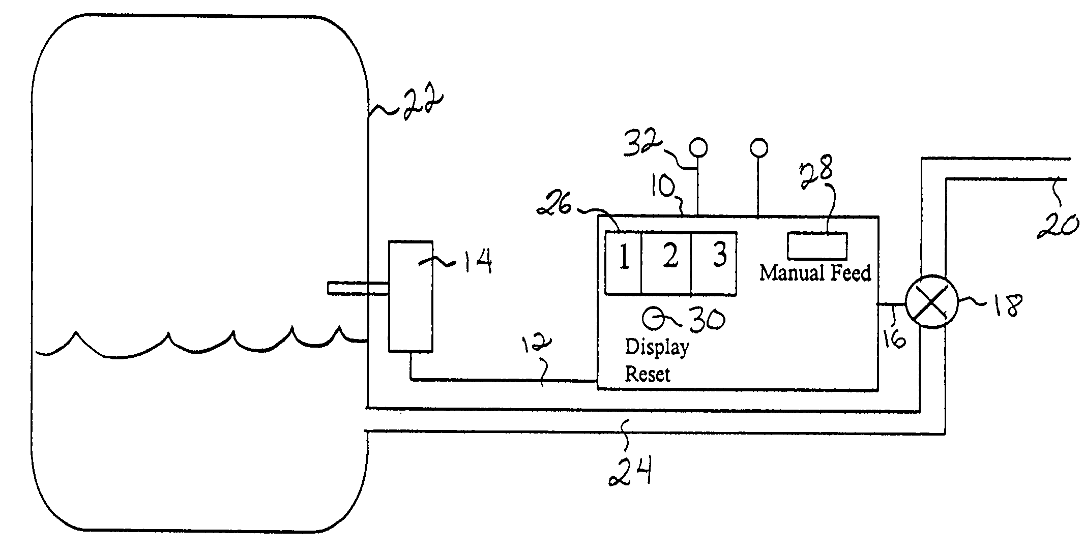
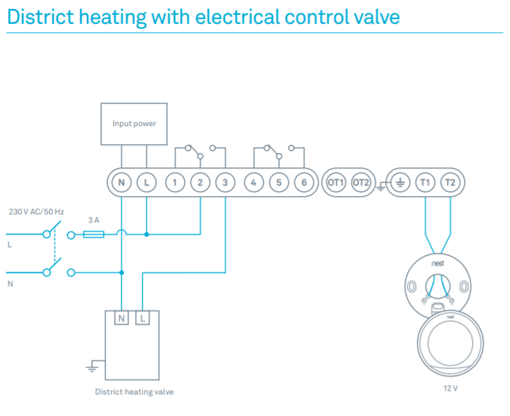
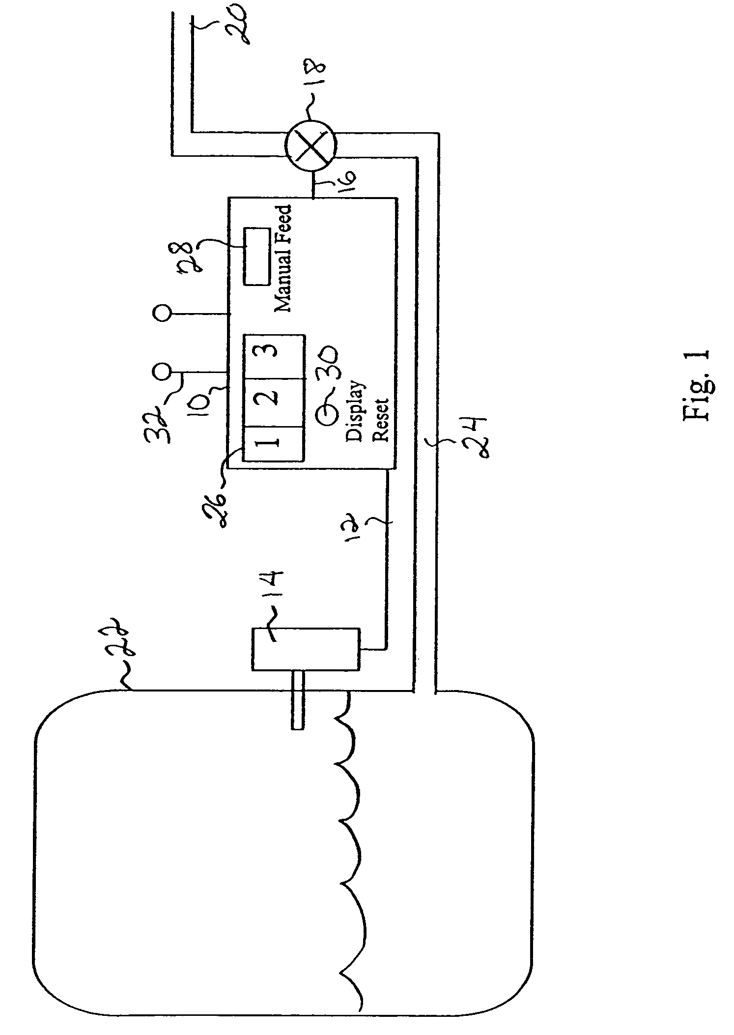
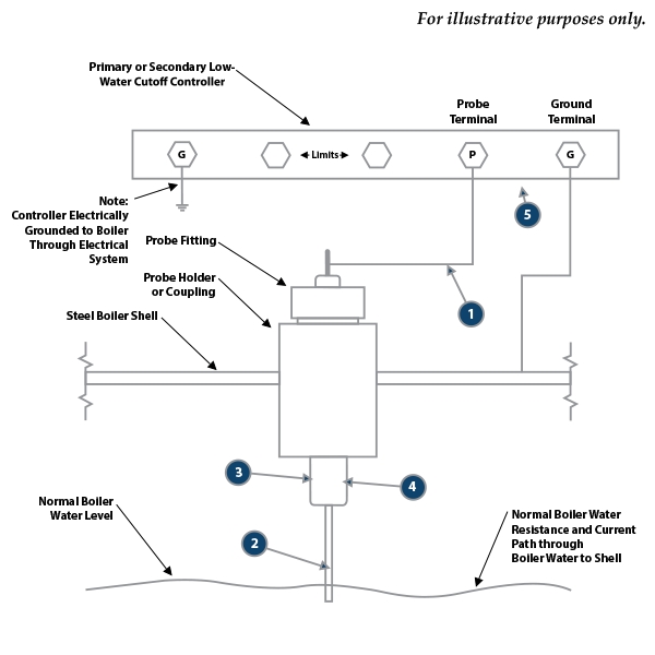
Mcdonnell miller low water cutoff wiring diagram. Mcdonnell Miller Low Water Cutoff Wiring Diagram – mcdonnell miller low water cutoff wiring diagram, Every electrical arrangement is made up of various distinct pieces. Each component ought to be placed and connected with other parts in particular manner. Otherwise, the arrangement won’t work as it ought to be. This can be used to operate a low water alarm or a McDonnell & Miller electric water feeder. NOTE: Connect hot wire to terminal marked (2) ahead of all controls.See diagram 1 on the following page (page 7) for control operation. See diagrams 2-4 on the following page (page 7) for proper application wiring. Wiring Instructions Mcdonnell Miller Xylem Applied Water Systems United States Mcdonnell Miller 166300 93 7b Lwco Pump Controller ... Bcb29 Low Water Cut Off Wiring Diagram Digital Resources Http Bostonheatingsupply Com Burnham Burnham 20independence 20i O 20manual Pdf 2 PS-852 models can be used as secondary low water cut-offs ... McDonnell & Miller. Installation & Maintenance ... wiring diagram and proceed to that page.12 pages
This can be used to operate a low water alarm or a McDonnell & Miller electric water feeder. Wiring Diagrams: Series 69 Low Water Cutoff with M&M Model 101-A ... McDonnell Miller Series 67 Low water cut-off for commercial, residential or industrial applications. Quick hook-up fittings provided. Lever-operated, full port ball. INSTRUCTION MANUAL The Series is identical to Series 67 in all . For 67 Low Water Cut-Off Installed with McDonnell & Miller Uni-Match Water-Feeder. Features and Benefits. wiring diagram and proceed to that page. ... For McDonnell & Miller Model 101A-120 Feeder and Series 67 Low Water Cut-Off with 24 volt burner circuit.8 pages At Low Water Cut-Off Level Boiler feed pump on–burner off–alarm on. 118 Basic Wiring McDonnell & Miller 14. AirFlwSwtchs114-120• 3/6/07 2:13 PM Page 118. 119 Basic Wiring McDonnell & Miller LWCO & Water Feeder Wiring 24V BURNER • 120V FEEDER 120V BURNER • 24V FEEDER ... These are suggested wiring diagrams but not the only solution to ...
We recommend that secondary (redundant) Low Water Cut-Off controls be installed ... McDonnell & Miller ... Following the appropriate wiring diagram, (refer.12 pages McDonnell & Miller Low Water cut-offs are specially designed to protect steam and hot water boilers from the hazards of a low water condition. In operation they will interrupt the electrical current to the firing device, if the water in the system drops below the boiler manufacturer’s minimum safe water level. Our low water cut-offsRead more Low Water Cut Off Wiring Diagram | Manual E-Books – Mcdonnell Miller Low Water Cutoff Wiring Diagram. Wiring Diagram comes with a number of easy to follow Wiring Diagram Directions. It really is supposed to aid all of the typical person in developing a proper method. These instructions will probably be easy to grasp and apply. (1) screw that secures the low water cut-offs switch housing (Y). BB b. Using a flathead screwdriver, remove the two (2) screws that secure the feeder cover(BB). For 67 Low Water Cut-Off Installed with McDonnell & Miller Series 101-A Water-Feeder For the 120V Burner/120V Feeder setups. BURNER 120 VAC SUPPLY 12 34 N H 101A 69 c. Using a wire nut ...
MCDONNELL MILLER LOW WATER CUT OFF SWITCH MODEL NO. 2 | eBay
This low water cut-off must be installed in series with all other limit and operating ... McDonnell & Miller ... Some boiler wiring diagrams indicate.8 pages

Mcdonnell Miller Low Water Cutoff Wiring Diagram

153825 - Mcdonnell & Miller 153825 - 6667, Insert for ...
67 LWCO wiring torubles (STEAM) — Heating Help: The Wall
Fluid Handling Recalls Low Water Cut-Off Control Units for ...

Mcdonnell Miller Water Feeder Wiring Diagram - Wiring ...
McDonnell & Miller PS-801-120 Electronic 120V Low Water ...

McDonnell & Miller No. 67 Low Water Cut-Off - USED | eBay

35 Low Water Cutoff Wiring Diagram - Wiring Diagram Database

Guard Dog Low Water Cutoff Wiring Diagram - Hanenhuusholli
Mcdonnell Miller Low Water Cutoff Wiring Diagram - TURDZOS

McDonnell & Miller PS-852-24 Electric Low Water Cut-Off | eBay
Mcdonnell Miller 67 Wiring Diagram

Mcdonnell Miller Low Water Cutoff Wiring Diagram - 24
Mcdonnell Miller Low Water Cutoff Wiring Diagram

Collection Of Safgard Low Water Cut Off Wiring Diagram ...

Mcdonnell Miller Low Water Cutoff Wiring Diagram
35 Low Water Cutoff Wiring Diagram - Wiring Diagram Database

I have a Low Water Cut Off control on a solid fuel boiler ...

NOS McDonnell Miller No.2 Switch Model 2 For Low Water Cut ...

25 Mcdonnell Miller Low Water Cutoff Wiring Diagram ...
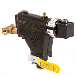
149400 - Mcdonnell & Miller 149400 - 67, Float Type Low ...
Mcdonnell Miller 67 Wiring Diagram
Mcdonnell Miller Low Water Cutoff Wiring Diagram For Your ...

Mcdonnell Miller Low Water Cutoff Wiring Diagram
Mcdonnell Miller Water Feeder Wiring

McDonnell & Miller PS-802-24 Electronic 24V Low Water Cut ...

Mcdonnell Miller Low Water Cutoff Wiring Diagram
143600 - Mcdonnell & Miller 143600 - 64, Float Type Low ...

Safgard Low Water Cut Off Wiring Diagram Download

Guard Dog LWCO Low Water Cut-Off Switch - 24VAC | Pexheat.com

MCDONNELL & MILLER 369 LOW WATER CUT-OFF | Star Mechanical ...
144676 - Mcdonnell & Miller 144676 - RB-122E, Electronic ...

142400 - Mcdonnell & Miller 142400 - 63, Float Type Low ...
Wiring Residential Gas Heating Units

Mcdonnell Miller Water Feeder Wiring
Low Water Cutoff Wiring Diagram - Atkinsjewelry

Wiring Residential Gas Heating Units
Mcdonnell Miller 67 Wiring Diagram

McDonnell & Miller Low Water Cut-Off Head Mechanism 64-HD ...
35 Low Water Cutoff Wiring Diagram - Wiring Diagram Database
0 Response to "41 mcdonnell miller low water cutoff wiring diagram"
Post a Comment