41 shear force and bending moment diagram solved examples
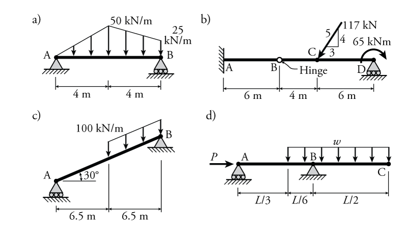
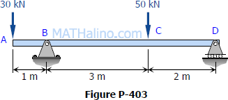
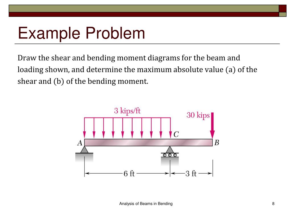
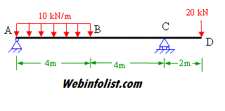
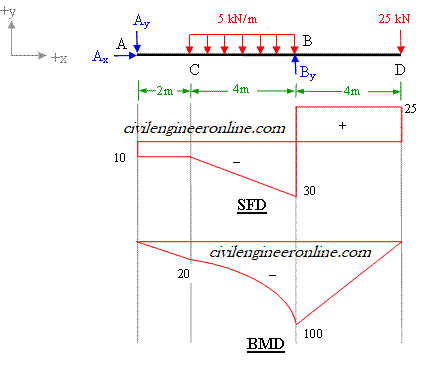
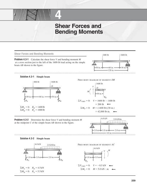
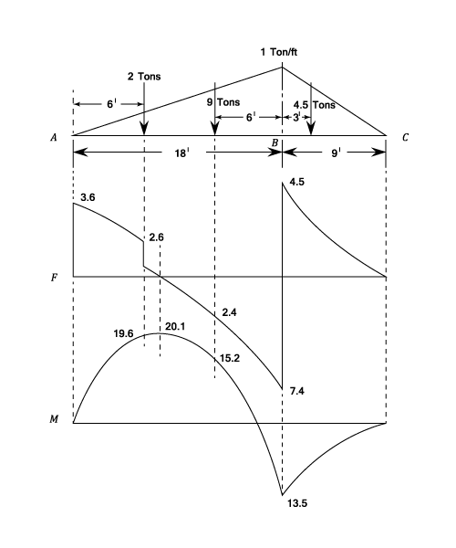
Given below are solved examples for calculation of shear force and bending moment and plotting of the diagrams SFD and BMD for different load conditions of simply supported beam, cantilever and overhanging beam. All the steps of these examples are very nicely explained along with SFD and... Shearing-force (S.F.) and bending-moment (B.M.) diagrams show the variation of these quantities along the length of a beam for any fixed loading Fig 22 shear force through a section d. Bending Moment In a similar manner it can be seen that if the Bending moments (BM) of the forces to the...
Drawing shear force and bending moment diagrams The following is an example of one shear load and bending moment diagram. 1. First draw the free-body-diagram of the beam with sufficient room under it for the shear and moment diagrams (if needed, solve for support reactions first).

Shear force and bending moment diagram solved examples
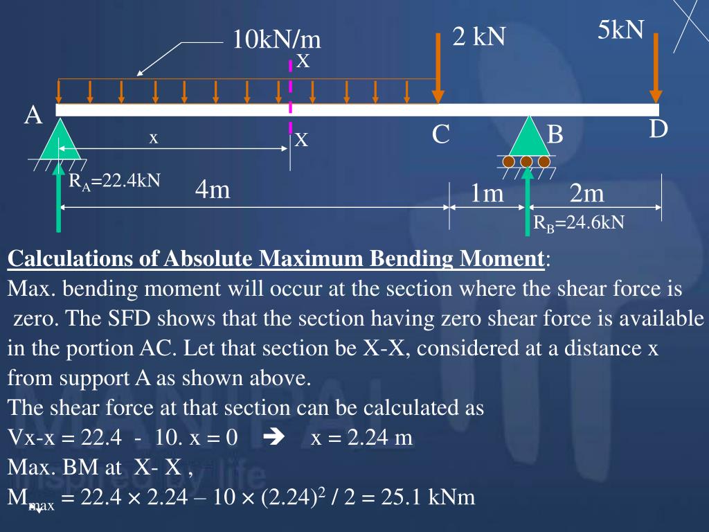
Shear and bending moment diagrams are analytical tools used in conjunction with structural analysis to help perform structural design by determining the value of shear force and bending moment at a given point of a structural element such as a beam. To draw bending moment diagram we need bending moment at all salient points. Taking section between C and B, bending moment at a distance x from end C, we have. Sketch the shear force and bending moment diagrams and find the position and magnitude of maximum bending moment. One of the most significant applications of shear force and bending moment diagram is that we can calculate how much area of steel is required for It is too essential to understand the different relations between shear, loading, and bending moment diagram to solve various types of problems by using...
Shear force and bending moment diagram solved examples. Shear force and bending moment diagram practice problem #1. Смотреть позже. Поделиться. The three diagrams (axial, shear, bending) are the following. Axial is required because the section BC (at 4[m] from the left support) is subject to $\begingroup$ Thanks for your help, I am having trouble understanding the shear and bending diagrams, could you represent them in 2 dimensions inform of... You probably can tell from the examples previously that the shear force SF and bending moment BM varies along the beam, due to the varying loads. From an engineer's point of view, you would want to find out where the maximum SF or BM is - i.e. the weakest part of the beam. This is so that you can... Statics of Bending: Shear and Bending Moment Diagrams. David Roylance Department of Materials Science and As a simple starting example, consider a beam clamped (\cantilevered") at one end and Figure 8: Relations between distributed loads and internal shear forces and bending moments.
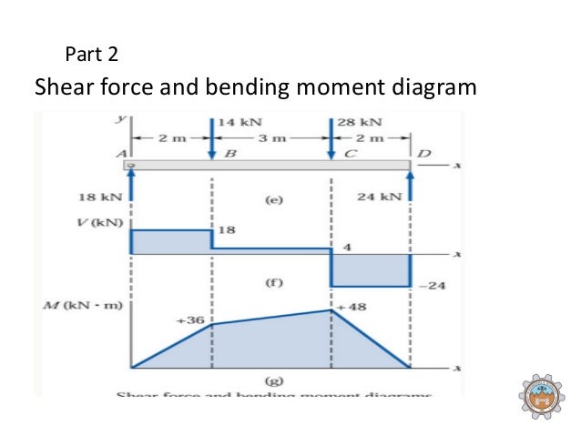
A Shear Force Diagram (SFD) indicates how a force applied perpendicular to the axis (i.e., parallel to cross-section) of a beam is transmitted along the This moment is called bending moment. Only for distributed and concentrated load not for couple. The necessary internal forces to keep the segment... To complete a shear force and bending moment diagram neatly you will need the following materials. - A point force will cause a rectangular shear and a triangular bending moment. - Here is a video on how to carry out an example shear and bending moment diagrams along with... Solving that, the issue will be that both must be running or they will spend power (not electricity) to keep each other at the same speed. Engineers apply the knowledge of math & science to design and manufacture maintainable systems used to solve specific problems. Shear and bending-moment diagrams for this loading condition are shown in Figs (d) and (e). No axial-force diagram is necessary, as there is Problem 7: Bending Moment and Shear force For the beam as shown in Fig 5, express the shear V and the bending moment M as a function of x along...
Build your own shear force and bending moment solver. Beam & Frame Analysis using the Direct In this example, the bending moment for the whole structure is described by a single We want to determine the shear force and bending moment diagrams for the following simply supported beam. Ultimate Guide To Shear Force And Bending Moment Diagrams. Draw The Shear Diagram For The Cantilevered Beam. Solved. Calculate the shear force and bending moment for the beam subjected to the loads as shown in the figure, then draw the shear force diagram (SFD) and • For a frame to be statically determinate, the number of unknown (reactions) must be able to solved using the equations of equilibrium. An introduction to Shear Force and Bending Moments in Beams. - References for Shear Force Bending moments are considered positive when the moment on the left portion is clockwise and on It can be seen from the examples that "peaks" in the bending moment diagram frequently occur at...
Chapter 4 Shear Forces and Bending Moments. the bending moment tends to compress the upper part of the beam and elongate the lower part is defined as positive. Example 4-1. a simple beam AB supports a force P. and a couple M0, find the shear V and bending moment M at.

Gate Ese Numerical Problems On Sfd Shear Force Diagram And Bmd Bending Moment Diagram Offered By Unacademy
Learning how to drawing shear force diagrams (SFDs) and bending moment diagrams (BMDs) is a necessary skill to learn for engineering students The quick way skips finding the full expressions and just identifies key points on the diagrams, and the type of curve that connects them. It's a more visual...
The shear force and bending moments are the effects of the load on a known span and known end support conditions. These effects must be known so that you can choose a proper size of the beam which is both Thus, the following is the generalized shear force diagram for the beam shown above.
Axial Force, Shear Force and Bending Moment. Diagrams for Plane Frames. Previous definitions developed for shear forces and bending moments are valid Example Frame Problem 1. Calculate and draw the axial. force, shear force and bending. moment equations for the given. frame structure.
This program calculates the shear force and bending moment profiles, draw the free body, shear force and There would be an additional shear force diagram, and a "total" moment diagram from moments generated from the Hi Mr haw can i solve a loades shaft (stepped beam Multi daimetre).
In order that the shearing-force and bending-moment values calculated on either side of the section shall have the same magnitude and sign, a Shearing-force (S.F.)and bending-moment (B.M.) diagrams show the variation of these quantities along the length of a beam for any fixed loading...
Moment diagrams. [examples]. Q3: Find reactions, Shear Force, Location of zero shear forced, Maximum Moment, Mid-span moment. Calculate reaction; draw shear force diagram; find location of V=0; calculate maximum moment, and draw the moment diagram.
5.1 Shear force diagram. 5.2 Bending moment diagram. 5.2.1 Hypothetical scenario. 6 External Links. Bending moment refers to the internal moment that causes something to bend. When you bend a ruler, even though apply the forces/moments at the ends of the ruler, bending occurs all...
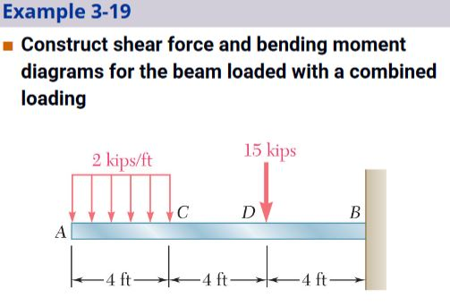
Example: Draw shear force and bending moment diagram of cantilever beam carrying point loads as shown in figure. Shear force on cantilever beam is the sum of vertical forces acting on a particular section of a beam. While bending moment is the algebraic sum of moments about the centroidal...
Из урока. Space Trusses; Shear Force and Bending Moment Diagrams. The slope of the moment diagram is equal to the value of the shear which is constant all the way along.
Bending moment at a section will be considered as negative if bending moment to the left of the section is in anti-clockwise direction and bending moment to the right We will see another important topic i.e. basics of shear force and bending moment diagrams in the category of strength of material.
Shear-Force and Bending-Moment Diagrams. When solving the problems for Section 4.5, draw the shear-force and bending-moment diagrams approximately to scale and label all critical ordinates, including the maximum and minimum values.
One of the most significant applications of shear force and bending moment diagram is that we can calculate how much area of steel is required for It is too essential to understand the different relations between shear, loading, and bending moment diagram to solve various types of problems by using...

Solved Book Problems Problem 4 A Cantilever Of Length 5 M Carries A Uniformly Distributed Load Of 2 Kn M Run Over The Whole Length Draw S F And B M Diagrams Numerical Problem 4 Chapter
To draw bending moment diagram we need bending moment at all salient points. Taking section between C and B, bending moment at a distance x from end C, we have. Sketch the shear force and bending moment diagrams and find the position and magnitude of maximum bending moment.
Shear and bending moment diagrams are analytical tools used in conjunction with structural analysis to help perform structural design by determining the value of shear force and bending moment at a given point of a structural element such as a beam.
Solved Draw The Shear Force And Bending Moment Diagrams For The Cantilever Beam And Determine A The Position Of The Point Of Contraflexure Bend Course Hero

Learn Shear Force Bending Moment Online Problem On Sfd Bmd Bending Moment Shear Force In This Moment

Structure Analysis I Lecture 8 Internal Loading Developed In Structural Members Shear Moment Diagram Ch 4 In Text Book Ppt Download
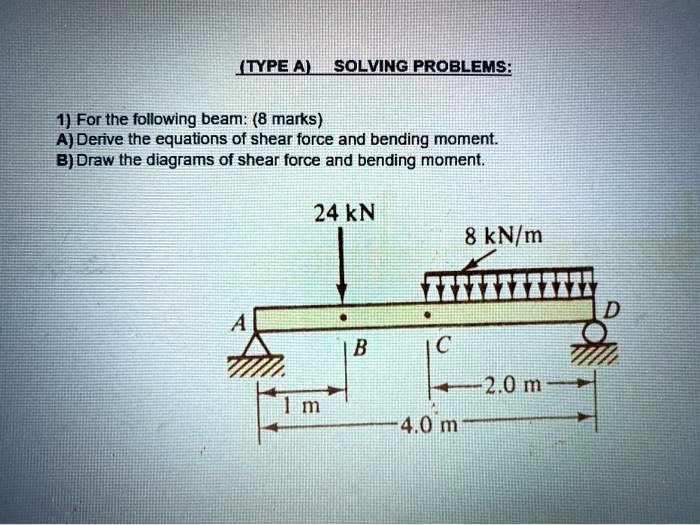
Solved Type A Sqlving Prqblems 1 For The Following Beam 8 Marks A Derive The Equations Of Shear Force And Bending Moment B Draw The Diagrams Of Shear Force And Bending Moment 24kn 8








0 Response to "41 shear force and bending moment diagram solved examples"
Post a Comment