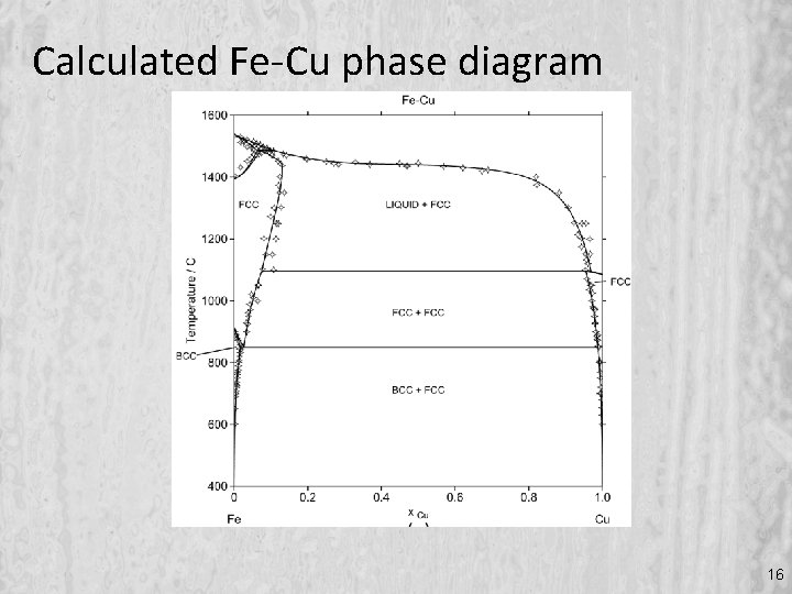
42 fe cu phase diagram
... Thus, the Fe-Cu and FeCuB alloys solidified by natural cooling show two phases. These phases are a solid solution Fe-Cu and a small portion of Fe 2 B, as ... An Ellingham diagram is a graph showing the temperature dependence of the stability of compounds. This analysis is usually used to evaluate the ease of reduction of metal oxides and sulfides.These diagrams were first constructed by Harold Ellingham in 1944. In metallurgy, the Ellingham diagram is used to predict the equilibrium temperature between a metal, its oxide, and oxygen — and by ...
The Al-Si Phase Diagram Published by Buehler, a division of Illinois Tool Works ... and Fe are common impurities found in aluminum alloys, but silicon is also a deliberate alloying addition in both cast and wrought Al alloys. Cast Al alloys can contain Si in amounts from about 5 to 22 weight percent. At this level, Si improves the fluidity and castability of aluminum. The 3xx.x (Al-Si-Cu) and ...

Fe cu phase diagram
Download scientific diagram | A calculated Fe-Cu phase diagram, together with the experimental data points [105, 124-135]. The solid lines refer to the ... 1. INTRODUCTION Recent phase diagram calculated on the Fe-Cu system, in general fit closely to experimental data. However, the calculation due to Kubaschewski et al. (1) yields a rather low solubility of Cu in f-iron while the calculation by Hasebe and Nishizawa (2) yields a higher solubility of Cu in y-iron especially at temperatures where y ... This repository provides a source for interatomic potentials (force fields), related files, and evaluation tools to help researchers obtain interatomic models and judge their quality and applicability. Users are encouraged to download and use interatomic potentials, with proper acknowledgement, and developers are welcome to contribute potentials for inclusion.
Fe cu phase diagram. 01.07.2004 · The fcc phase field includes the composition Fe 20 Cr 20 Mn 20 Ni 20 Co 20, and is capable of dissolving substantial amounts of Nb, Ti and V, as well as smaller amounts of Cu and Ge. It presumably extends to include the fcc austenite phase in pure Fe, pure Ni and binary Fe–Ni alloys. The multicomponent fcc lattice parameter is in the range 0.358–0.364 The phase layers formed by the interdiffusion among pure Cu, pure Fe, and the Al 5 Fe 2 alloy correspond to γ-Fe, α-Fe, β, Cu 3 Al, and Al 2 Fe according to the corresponding binary phase diagrams [25,26,39]. Additional results from the alloy samples annealed at 1000 °C for 240 or 360 h were also collected to reveal the phase relations in ... Downloading the viewer: Click this link Phase Equilibria Diagram Viewer to download the PED Viewer. Enlarging a diagram: Click and drag the lower right corner of the diagram window to enlarge the diagram. Zoom In: Press and hold the left mouse button and drag down and to the right to open a red string box. When the mouse is released the area in the box will be enlarged. To zoom back out and ... ... [41] Fe-Cu system does not form any intermetallic compounds, and there is a wide miscibility gap between Fe and Cu in the equilibrium phase diagram ...
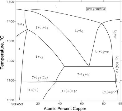
Aiming at a thermodynamic basis to investigate the effect of Cu addition on the Fe-C system, the CALPHAD (CALculation of PHAse Diagrams) approach was ... The C-Cu phase diagram [Massalski2] is of the simple peritectic type, with negligible mutual solubility between C and Cu. The C-Fe phase diagram [] is in the form of a double diagram, corresponding to metastable equilibrium with Fe 3 C (cementite) or stable equilibrium with graphite.The fcc solid solution γ (austenite) forms peritectically at 1493 °C. Review Fe-C phase diagram • 2 important points-Eutectoid (B): γ⇒α+Fe 3C-Eutectic (A): L ⇒γ+Fe 3C Fe 3 C (cementite) 1600 1400 1200 1000 800 600 400 0 12 3 4 5 66.7 L γ (austenite) γ+L γ+Fe 3C α+Fe 3C α + γ L+Fe 3C δ (Fe) C o, wt% C 1148°C T(°C) α 727°C = Teutectoid A R S 4.30 Result: Pearlite = alternating layers of αand Fe ... 金属やセラミックスの状態図、エンリンガム図などの情報を提供しています。 一部、不確かなものもありますので、自己 ...
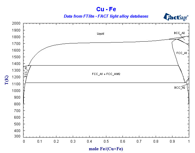
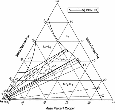
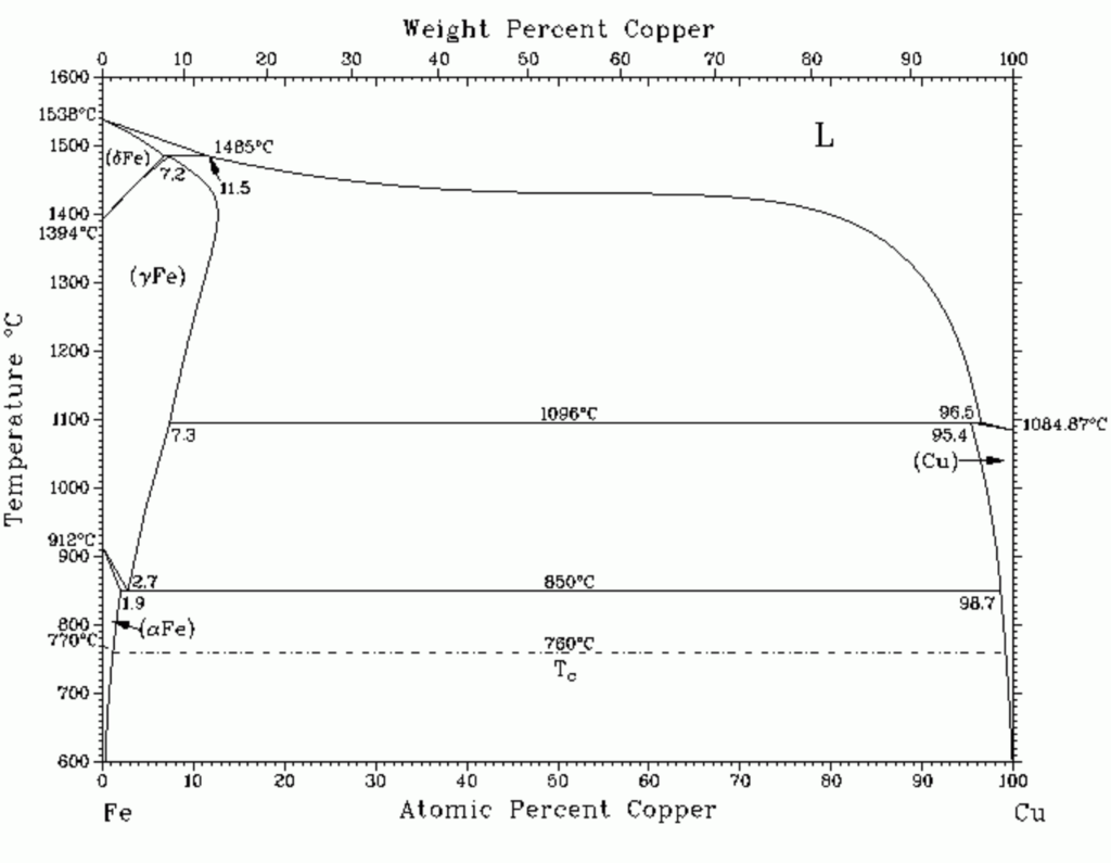
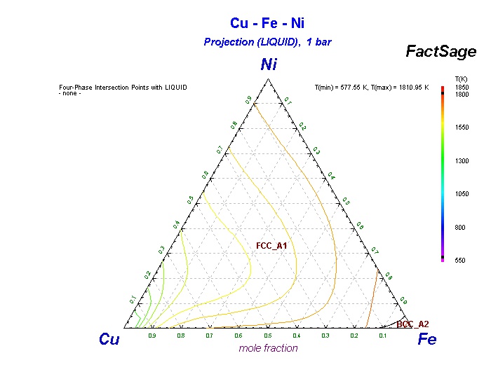
Phase diagram. This type of phase transformation is known as spinodal decomposition, and can be illustrated on a phase diagram exhibiting a miscibility gap. Thus, phase separation occurs whenever a material transitions into the unstable region of the phase diagram. The boundary of the unstable region, sometimes referred to as the binodal or coexistence curve, is found by performing a common ... A thermodynamic database of the Cu-Fe-X [X: aluminum (Al), cobalt (Co), chromium (Cr), manganese (Mn), molybdenum (Mo), niobium (Nb), nickel (Ni), vanadium (V)] systems was developed by the CALPHAD (Calculation of Phase Diagrams) method, where the Gibbs energies of solution phases such as the liquid, face-centered-cubic (fcc), body-centered-cubic (bcc), and hexagonal-close-packed (hcp) phases ... Copper and iron are slightly soluble in each other; a two-phase region can be seen in a wide range of concentrations in the phase diagram of Cu-Fe (Fig. 1). Iso-sulfur Activity Lines Cu-Fe-S System One Phase Region 98. 44. Iso-sulfur Activity Lines in Cu-Fe-S System. (Weight % Diagram) 100. 45. Log Pf126/p"2 Versus Composition of Matte Phase of Miscibility Gap. 135000 102. 46. Log PH2S/ 2 Versus Composition of Metallic Phase
Binary Fe Cu Phase Diagram With Metastable Liquid Miscibility Gap Download Scientific Diagram
Calculated metastable Fe–Cu–C phase diagram: (a) with 1 at% Cu excluding both graphite and diamond; (b) with 1 at% Cu excluding only graphite; (c) enlarged diagram of Fig. 16a and Fig. 16b (the two enlarged diagrams are identical). The metastable phase diagram without Cu and with 0.4 at% Cu are also included in Fig. 16c for comparison.
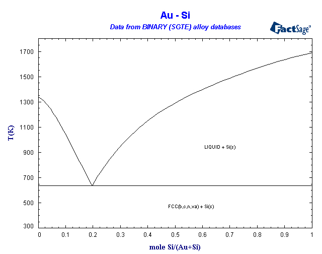
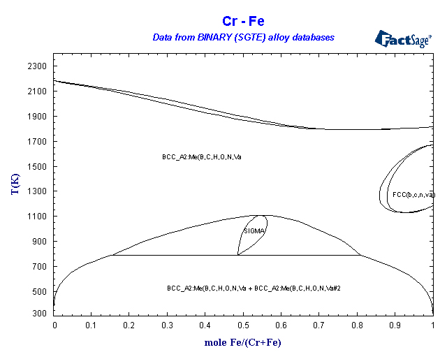
Binary Sgte Alloy Phase Diagrams
what a phase diagram is; how to read it; how phases change on heating and cooling; the resulting microstructures. When you have worked through this unit you should be able to do the following: (1) Interpret the equilibrium phases at any point on binary phase diagrams. (2) Predict the microstructures which may result from simple processing histories relating to solidification and heat treatment ...
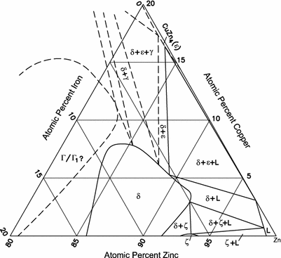
Cu Fe Zn Copper Iron Zinc Springerlink
These functions predict phase equilibria in close agreement with the experimental temperature-composition diagram and are represented in Fig. 17. Detailed information is shown in Figs. 18 and 19. During the determination of diffusion coefficients in the Fe-Cu system with an electron probe microanalyser [2] the solubility limits were also ...

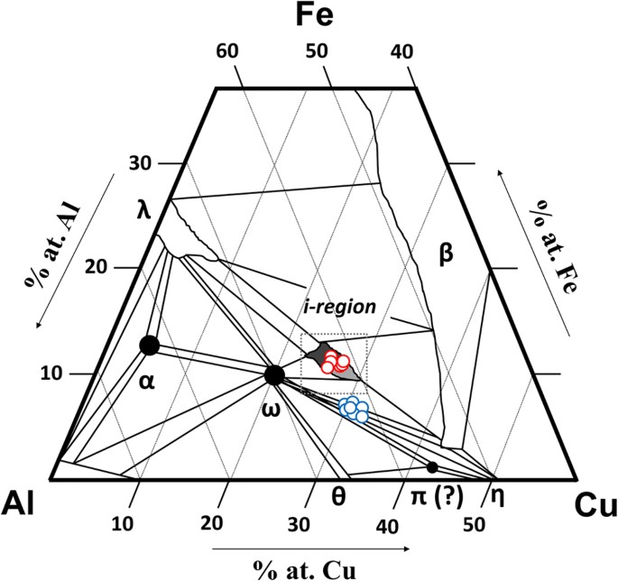
New Experimental Studies On The Phase Diagram Of The Al Cu Fe Quasicrystal Forming System Sciencedirect
temperature and obtained the isothermal phase diagrams of the system Cu-Fe-S at 500°C, 400°C, 350°C and 300°C. The minerals found in the Cu-Fe-S system appeared in this paper are listed in Table 1 together with its compositions, abbreviations and their thermal stability. Table 1.
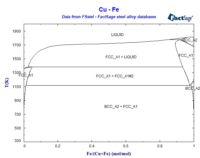
Fsstel Factsage Steel Alloy Phase Diagrams
Cu-Fe Phase Diagram. [2003Tur]. Thermodynamics of alloys and phase equilibria in the Copper-Iron system, M.A.Turchanin, P.G.Agraval, I.V.Nikolaenko, J.Phase ...
Phase Diagram Array
One Fe/Cu/FeC 0.05 (in wt%) diffusion couple was designed to further determine the phase equilibria of the ternary system. A set of self-consistent parameters for the Fe–Cu–C system was obtained after thermodynamic optimization. Good correspondence between calculated and experimental values of phase diagrams, thermodynamic properties, and ...
C Cu Fe Carbon Copper Iron Springerlink
Binary phase diagram If a system consists of two components, equilibrium of phases exist is depicted by binary phase diagram. For most systems, pressure is constant, thus independently variable parameters are –temperature and composition. Two components can be either two metals (Cu and Ni), or a metal and a compound (Fe and Fe3C), or two ...
Cu Fe Sn Copper Iron Tin Springerlink
Click on a system to display the phase diagram. (NH4)2SO4-H2O FTfrtz (NH4)2SO4-H2O_with_gas FTfrtz (NH4)2SO4-H2O-KNO3_100oC FTfrtz (NH4)2SO4-H2O-KNO3_125oC FTfrtz (NH4)2SO4-H2O-KNO3_25oC FTfrtz (NH4)2SO4-H2O-KNO3_50oC FTfrtz (NH4)2SO4-H2O-KNO3_75oC FTfrtz (NH4)2SO4-H2O-KNO3_LP FTfrtz (NH4)2SO4-H2O-NH4NO3_100oC FTfrtz (NH4)2SO4-H2O …

Geologic Ore Geology1 Phase Equilibria In Ore Bearing Systems
... equilibrium diagram of the Fe-Cu binary system ( Fig.1) points to a very low, practically insignificant miscibility of the two metals, each one ...

Diagrama De Faz Fe Cu 4 Figure 1 Equilibrium Phase Diagram Of Fe Cu Download Scientific Diagram
This repository provides a source for interatomic potentials (force fields), related files, and evaluation tools to help researchers obtain interatomic models and judge their quality and applicability. Users are encouraged to download and use interatomic potentials, with proper acknowledgement, and developers are welcome to contribute potentials for inclusion.
Solved Q1 1 18 Points Refer To The Iron Copper Phase Chegg Com
1. INTRODUCTION Recent phase diagram calculated on the Fe-Cu system, in general fit closely to experimental data. However, the calculation due to Kubaschewski et al. (1) yields a rather low solubility of Cu in f-iron while the calculation by Hasebe and Nishizawa (2) yields a higher solubility of Cu in y-iron especially at temperatures where y ...
Collisions In Outer Space Produced An Icosahedral Phase In The Khatyrka Meteorite Never Observed Previously In The Laboratory Scientific Reports
Download scientific diagram | A calculated Fe-Cu phase diagram, together with the experimental data points [105, 124-135]. The solid lines refer to the ...
Binary Sgte Alloy Phase Diagrams

Binary Sgte Alloy Phase Diagrams
2
Thermodynamic Data A Tutorial Course Session 8 Calculation
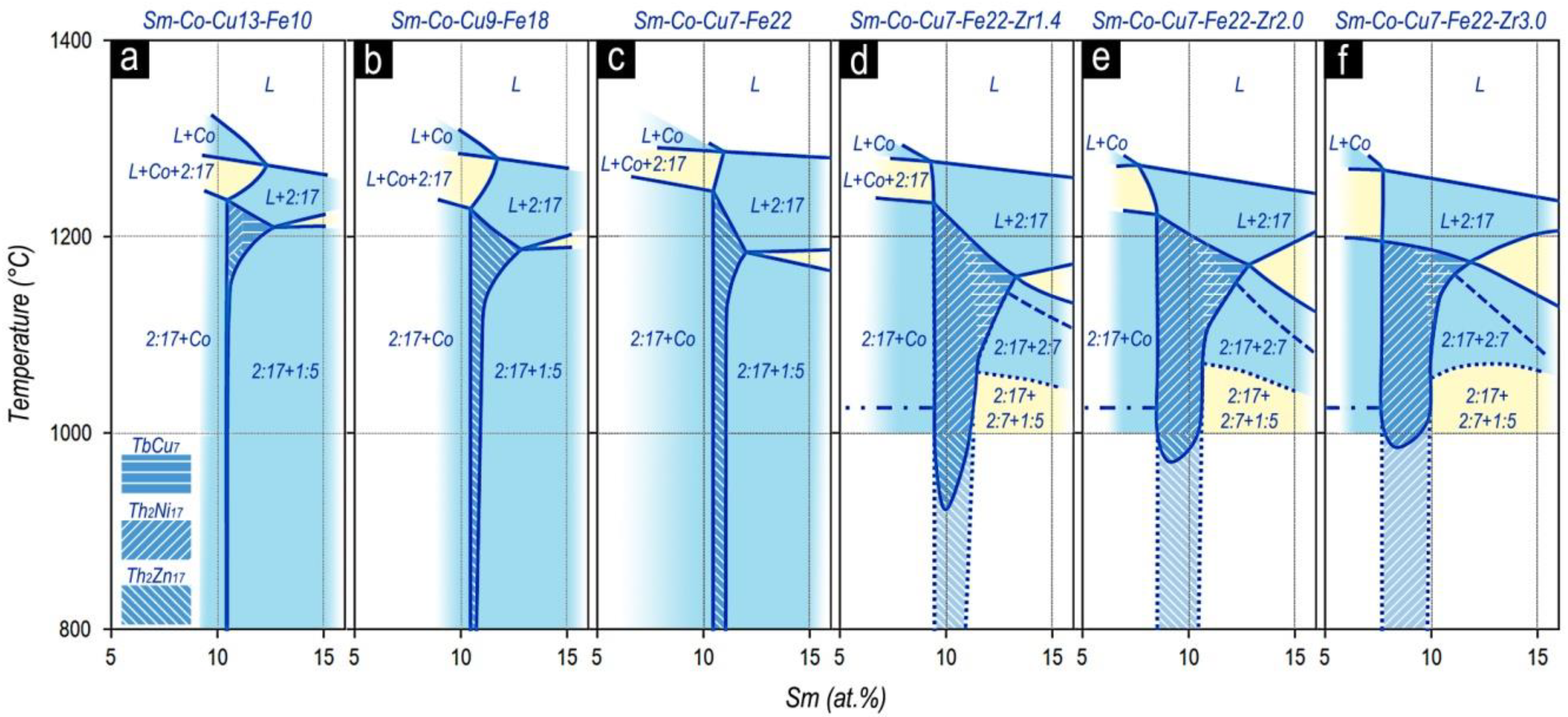
Materials Free Full Text Structure Of Alloys For Sm Zr Co Cu Fe Z Permanent Magnets First Level Of Heterogeneity Html
2

Characterization Of A Continuous Co2 Laser Welded Fe Cu Dissimilar Couple Iit Madras

Thermodynamic Assessment And Database For The Cu Fe O S System Sciencedirect
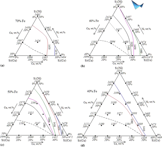
High Temperature Area Of The Fe Ni Co Cu Phase Diagram Experimental Study And Computer Design Springerlink

Scielo Brasil Phase Separation And Development Of The Microstructure For Stainless Steel To Copper Alloy Weld Joints Using A Fiber Laser Phase Separation And Development Of The Microstructure For Stainless

New Experimental Studies On The Phase Diagram Of The Al Cu Fe Quasicrystal Forming System Sciencedirect
Collection Of Phase Diagrams

Experimental Fe Cu Phase Diagram According To 1 Download Scientific Diagram
8 2 Phase Diagram Of The Cu Fe O System At 1000 C Jacob And Coworkers Download Scientific Diagram

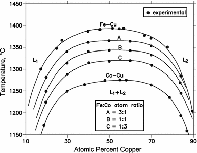
Location Of Fe60co20cu20 Alloy In Fe Co Cu Phase Diagram Download Scientific Diagram

Table I From The Al Cu Fe Phase Diagram 0 To 25 At Pct Fe And 50 Semantic Scholar
Phase Diagrams Evaluation

A Calculated Fe Cu Phase Diagram Together With The Recent Experimental Download Scientific Diagram

Chemical Synthesis And Properties Of Nanocrystalline Cu Fe Ni Alloys Sciencedirect

The Phase Diagram Of Cu Fe Alloy The Dashed Curve Under The Liquidus Download Scientific Diagram
1
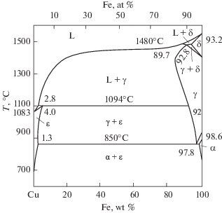
Figure 1 Investigation Of Two Phase State Of Fe Cu Melts During Cooling In A Viscometer Springerlink

Diagramma Sostoyaniya Sistemy Cu Fe
2
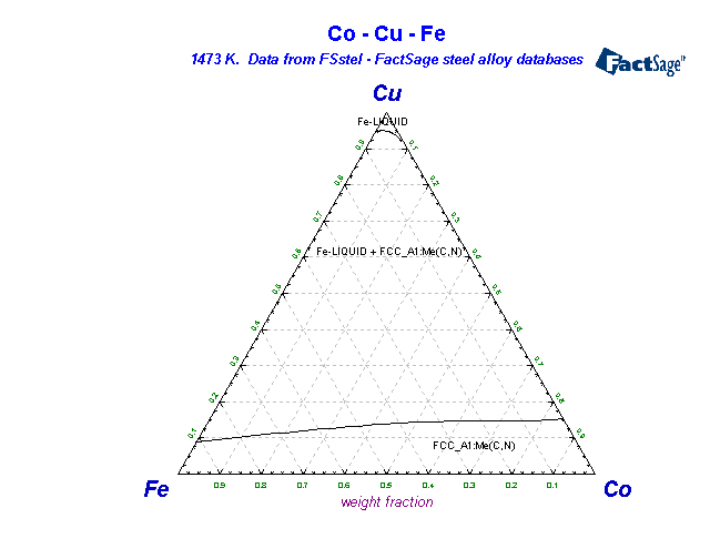
Co Cu Fe Cobalt Copper Iron Springerlink
Collection Of Phase Diagrams

Scielo Brasil Experimental Evaluation Of 300 ºc Section Of Cu In Ni Phase Diagram Hardness And Electrical Conductivity Of Selected Alloy Experimental Evaluation Of 300 ºc Section Of Cu In Ni Phase Diagram Hardness

Equilibrium Binary Fe Cu Phase Diagram Dashed Lines Represent S In Tie Download Scientific Diagram

Isothermal Section Of The Al Cu Fe Phase Diagram At A Temperature Of Download Scientific Diagram

Calculated Phase Diagram Of The Cu Fe System On The Cu Rich Side Data Download Scientific Diagram
0 Response to "42 fe cu phase diagram"
Post a Comment