37 petroleum refinery process flow diagram
fundamentals of petroleum refining, one must begin with crude oil. 3.1 The Chemical Constituents of Crude Oil Hundreds of different crude oils (usually identified by geographic origin) are processed, in greater or lesser volumes, in the world's refineries. Each crude oil is unique and is a complex mixture of thousands of compounds. Most of the A generalized natural gas flow diagram is shown in Figure 12.2 [7]. After initial scrubbing to remove particles, the first step in natural gas processing is the removal of condensate (oil) and water that is achieved by controlling the temperature and pressure of the inlet stream from the well, as shown in Figure 12.4.
topic discussed:Process flow diagram of refinery.---CHEMICAL ENGINEER Thank You for watching the video....Like, share and subscribe to the channel... Find us...

Petroleum refinery process flow diagram
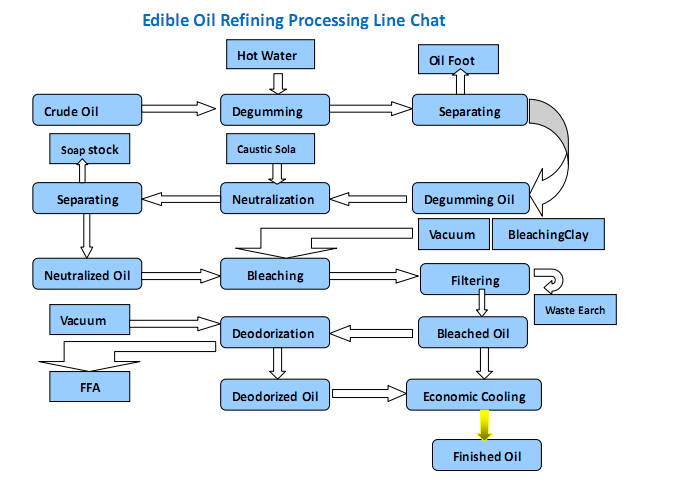
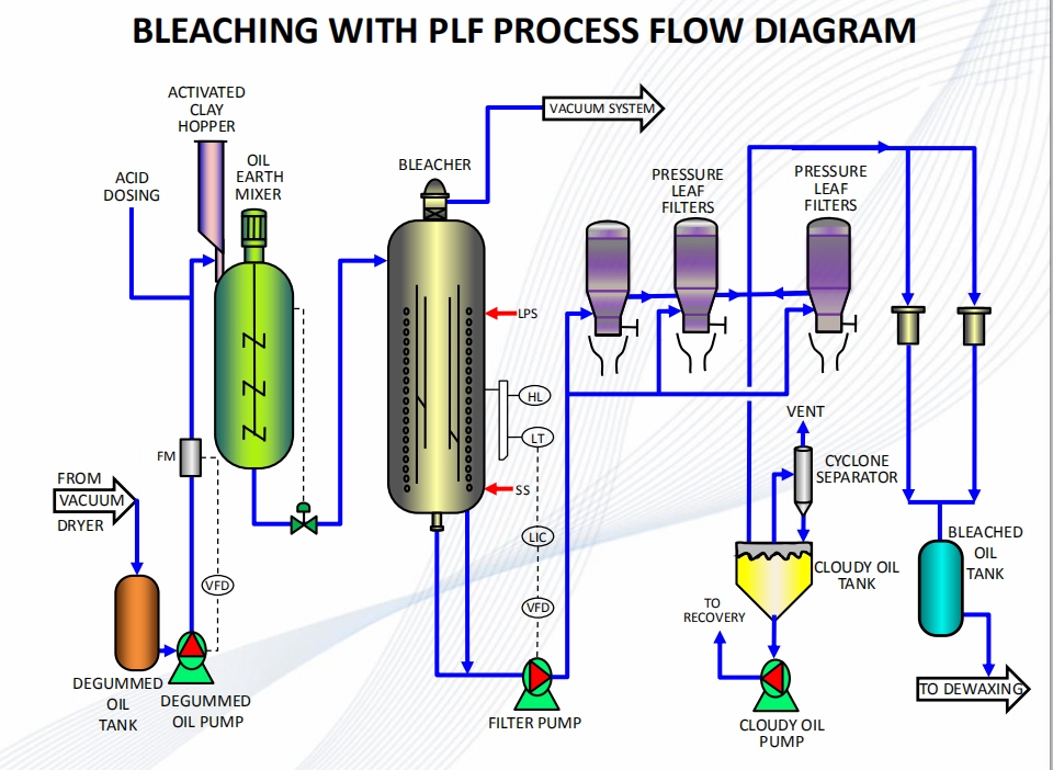
A Process Flow Diagram (PFD) is a diagram which shows the relationships between the main components in a system. Process Flow Diagrams are widely used by engineers in chemical and process engineering, they allows to indicate the general flow of plant process streams and equipment, helps to design the petroleum refineries, petrochemical and chemical plants, natural gas processing plants, and ... stripping process, any triglycerides and fatty acids remaining in the refined, bleached oil are removed and the refined-bleached- deodorized (RBD) oil is ready . for . processing into commercial products. A . process flow diagram for the edible oil processing operation is attached to this memorandum. . ', REFINERY— PROCESS FLOW DIAGRAMS 5 Process Flow Diagrams — Refinery Conversion Process — Typical Distillation Unit Process Desciptions One of the other feedstocks to a refinery is hydrogen, which can be used in a hydrotreater, isomerization, FCC, reformer, and a complex, capital-intensive unit.
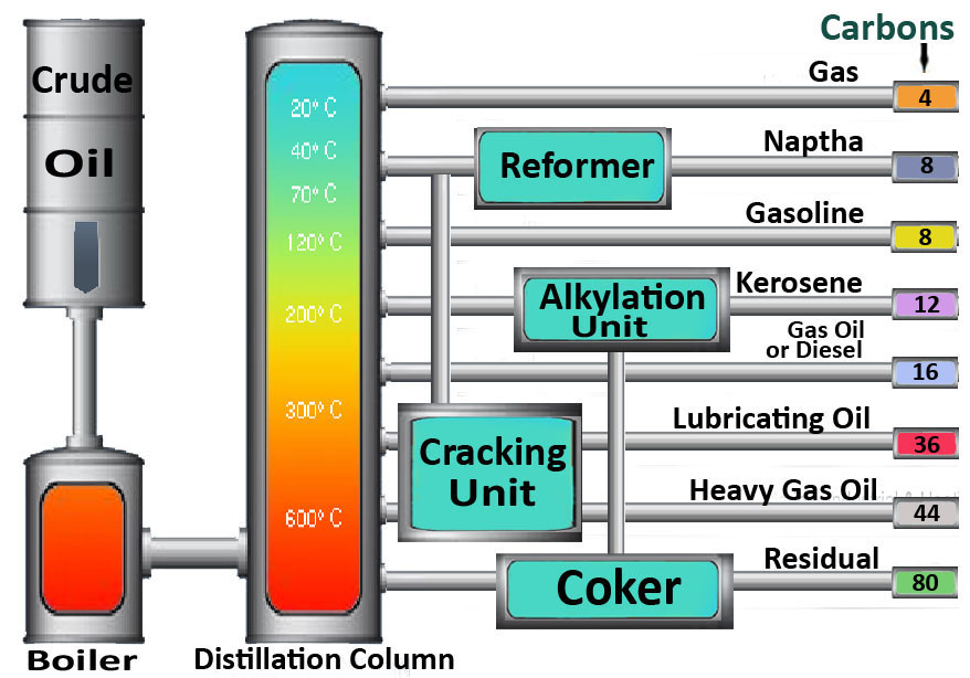
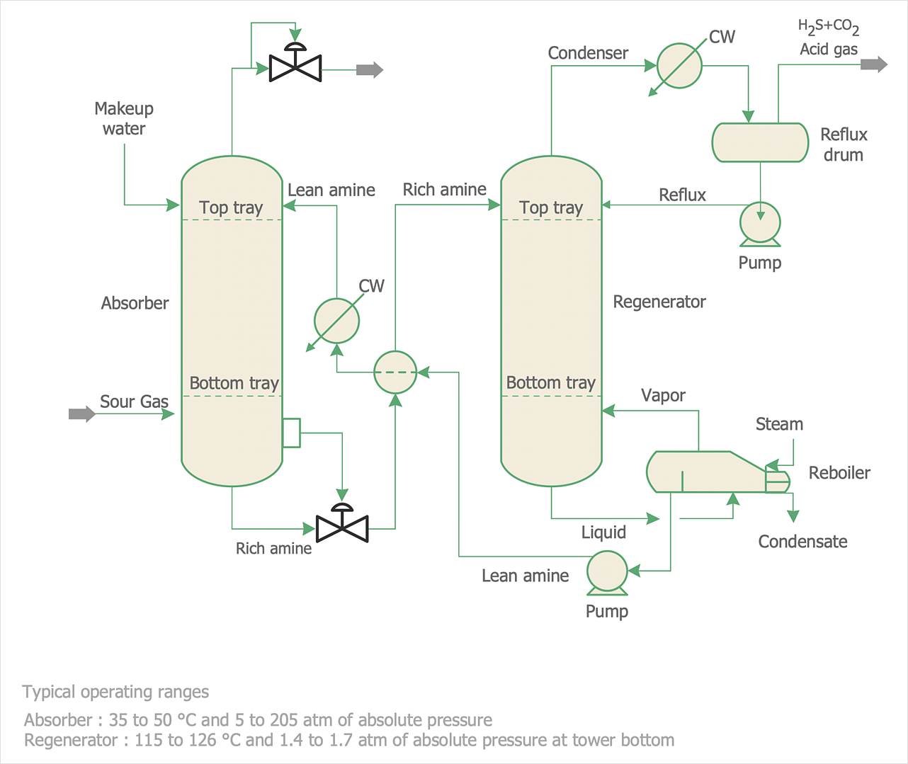
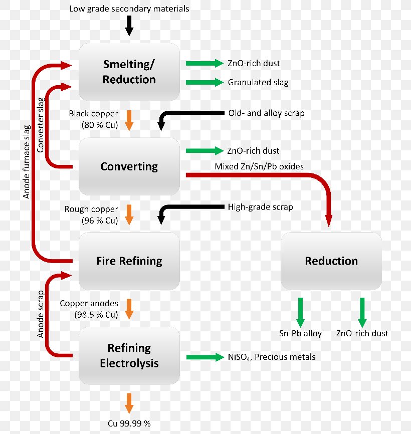
Petroleum refinery process flow diagram. Crude Oil as Refinery Feedstock • Crude Oil Complex mixture of hydrocarbons & heterocompounds Dissolved gases to non‐volatiles (1000 F+ boiling material) C 1 to C 90 + • Composition surprisingly uniform 41 Element Wt% Carbon 84 ‐87 Hydrogen 11 ‐14 Sulfur 0 ‐5 Nitrogen 0 ‐0.2 Other elements 0 ‐0.1 Crude desalting is usually the first step in a petroleum refining process. Crude oil enters into the refining unit from outside storage tanks and contains heavy amounts of contaminants, ... A process flow diagram of an amine-sweetening unit is shown in Figure 6. 8 Figure 6. Gas Oil hydrotreater treats gas oil before sending it to the fluid catalytic cracker unit (FCCU). The process flow diagram of a typical Hydroprocessing unit is shown below. Hydrotreating Process Flow Diagram. Following is the process description of the Hydrotreament plant which consists of different sections. This is a classification of refining processes and the types of refinery products shown by a flow chart. The flow chart starts with crude oil. Above crude oil chemical constitution is written and below physical properties are written. Crude oil leads to the refining process including separation, conversion, finishing and support.
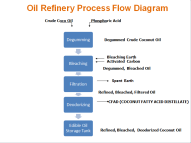
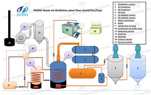
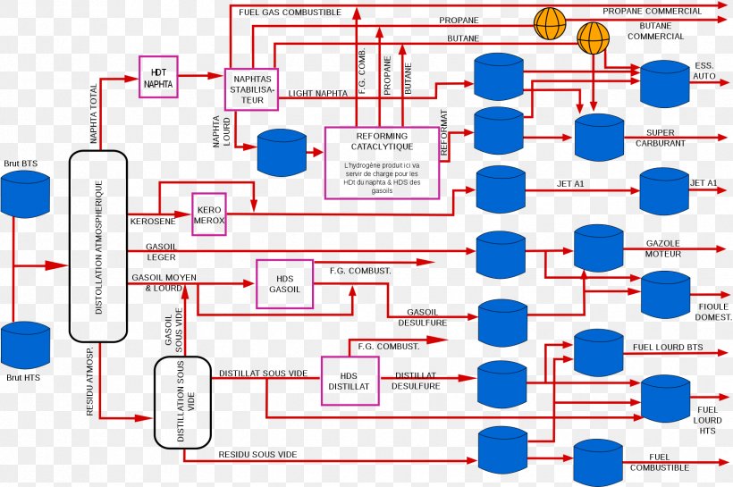
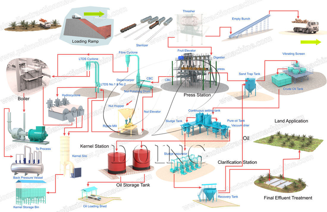
Continuous palm oil physical refining process flow chart. This continuous palm oil physical refining process flow chart is based on our engineers' designing palm oil physical refining technology, which is for 100tpd continuous palm oil refinery plant project in Kenya.It is different from other oil refining process, such as soybean oil refining process, sunflower oil refining process, etc. Petroleum Refinery Process Economics, 2nd ed. , by Robert E. Maples, PennWell Corp., 2000 75 blends 135 blends a 1 0.03224 0.03324 a 2 0.00101 0.00085 a 3 0 0 b 1 0.04450 0.04285 b 2 0.00081 0.00066 b 3-0.00645 -0.00632 Flow diagram of a typical petroleum refinery. The image below is a schematic flow diagram of a typical petroleum refinery that depicts the various refining processes and the flow of intermediate product streams that occurs between the inlet crude oil feedstock and the final end-products. 10 Application Solutions Guide — Refinery Process GLOBAL REFINERY LANDSCAPE Figure 1.4: In-process refinery end products and finished marketable refinery end products diagram API for valves The oil and gas industry does not use a universal API specification for valves like they have on pumps and
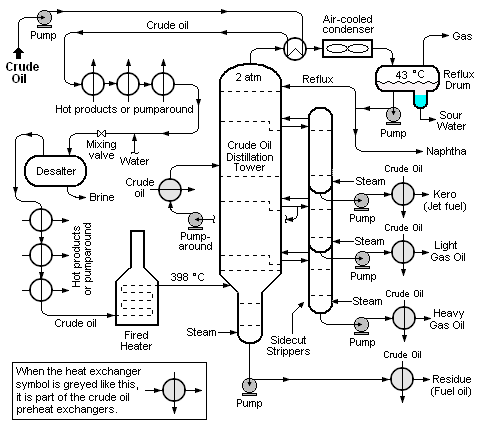
• Crude oil distillation is more complicated than product distillation, in part because crude oils contain water, salts, and suspended solids. • Step 1 in the refining process is to remove these contaminants so as to reduce corrosion, plugging, and fouling of equipment and to prevent poisoning catalysts in processing units. Crude Oil Refinery Flow Diagram Showing Process Chemical Additives Financial benefits Whether it be extending equipment life due to corrosion inhibition, increasing production output due to enhanced deposit control, or shortening the the start-up time during sulphidation operations, we have resolved to provide you Flow diagram of typical refinery. The image below is a schematic flow diagram of a typical oil refinery that depicts the various unit processes and the flow of intermediate product streams that occurs between the inlet crude oil feedstock and the final end products. The diagram depicts only one of the literally hundreds of different oil ... The petroleum refining industry employs a wide variety of processes. A refinery's processing flow scheme is largely determined by the composition of the crude oil feedstock and the chosen slate of petroleum products. The example refinery flow scheme presented in Figure 5.1-1 shows the general
The image on the following page is a schematic flow diagram of a typical oil refinery that depicts the various unit processes and the flow of intermediate product streams that occurs between the inlet crude oil feedstock and the final end products. The diagram depicts only one of the literally hundreds of different oil refinery configurations.
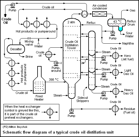
The first step of this process is not demonstrated at the diagram, which is the heating of the crude oil to a temperature of 100-150 °C. The freshwater presents another inlet stream in this process, and its volume flow represents the 4-10% of the crude oil volume flow. The third stream is composed of the demulsifying agent.
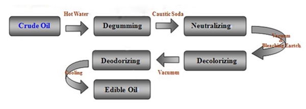
Edible Oil Processing Flow Chart. Vegetable oil refinery plant hot soybean oil refining process palm oil processing hine flow chart of palm kernel oil refining small scale edible oil refinery line. Simplified Schematic Diagram Of Soybean Vegetable Oil Refining Processes Scientific. An Exle Of Full Processing Flow Chart For A Palm Oil Refining ...
Petroleum Refining Industry Study 5 August 1996 Table 3.7.5. Spent Dimersol Polymerization Catalyst Physical Properties..... 89 Table 3.7.6.

This video was created for Penn State's F SC 432: Petroleum Processing course (https://www.e-education.psu.edu/egee101/) with the assistance of Semih Eser an...

Petroleum Refining. Petroleum refining is basically a heat and mass flow process in a continuous steady-state condition by separation of products based on their boiling points [2]. From: Thermofluid Modeling for Energy Efficiency Applications, 2016. Download as PDF.

Petroleum Refinery Process Create Process Flow Diagram examples like this template called Petroleum Refinery Process that you can easily edit and customize in minutes. 2/16 EXAMPLES

Flow diagram of a typical petroleum refinery. The image below is a schematic flow diagram of a typical petroleum refinery that depicts the various refining processes and the flow of intermediate product streams that occurs between the inlet crude oil feedstock and the final end-products.
A Process Flow Diagram (PFD) is a diagram which shows the relationships between the main components in a system. Process Flow Diagrams are widely used by engineers in chemical and process engineering, they allows to indicate the general flow of plant process streams and equipment, helps to design the petroleum refineries, petrochemical and chemical plants, natural gas processing plants, and ...
Petroleum Refining Fourth Year Dr.Aysar T. Jarullah Alkylation Process Alkylation is the process of producing gasoline range material light olefins (primarily ... A block diagram of the process is shown in Figure below: Process Flow: Sulfuric Acid Alkylation In sulfuric acid (H 2 SO 4 ) alkylation units, the feeds - propylene, butylene ...

An oil refinery or petroleum refinery is an industrial process plant where petroleum (crude oil) is transformed and refined into useful products such as gasoline (petrol), diesel fuel, asphalt base, fuel oils, heating oil, kerosene, liquefied petroleum gas and petroleum naphtha. Petrochemicals feedstock like ethylene and propylene can also be produced directly by cracking crude oil without the ...
REFINERY— PROCESS FLOW DIAGRAMS 5 Process Flow Diagrams — Refinery Conversion Process — Typical Distillation Unit Process Desciptions One of the other feedstocks to a refinery is hydrogen, which can be used in a hydrotreater, isomerization, FCC, reformer, and a complex, capital-intensive unit.
stripping process, any triglycerides and fatty acids remaining in the refined, bleached oil are removed and the refined-bleached- deodorized (RBD) oil is ready . for . processing into commercial products. A . process flow diagram for the edible oil processing operation is attached to this memorandum. . ',
A Process Flow Diagram (PFD) is a diagram which shows the relationships between the main components in a system. Process Flow Diagrams are widely used by engineers in chemical and process engineering, they allows to indicate the general flow of plant process streams and equipment, helps to design the petroleum refineries, petrochemical and chemical plants, natural gas processing plants, and ...


0 Response to "37 petroleum refinery process flow diagram"
Post a Comment