37 single phase to three phase converter circuit diagram
Rotary 3 Phase Converter Wiring Diagram - heretup. Collection of 3 phase rotary converter wiring diagram. A wiring diagram is a streamlined standard photographic depiction of an electric circuit. It shows the elements of the circuit as simplified shapes, and the power and also signal connections between the tools. 3 Phase Converter Wiring Diagram.
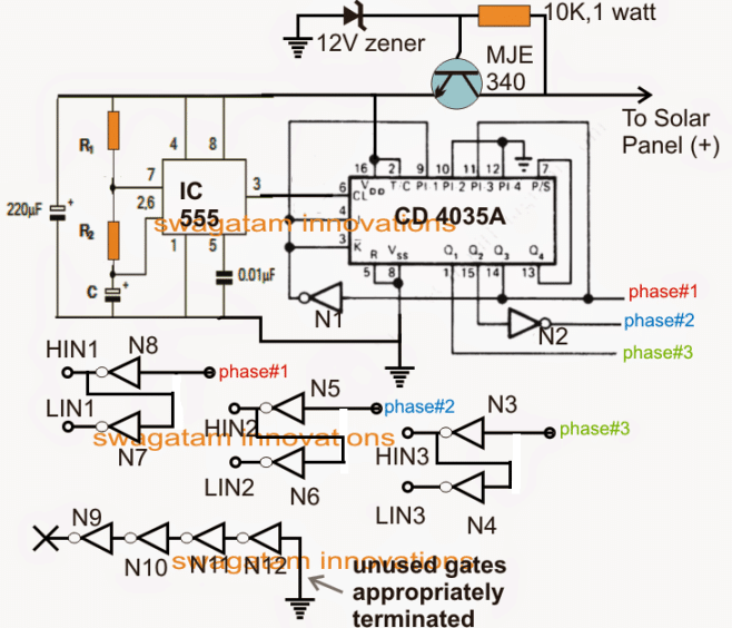
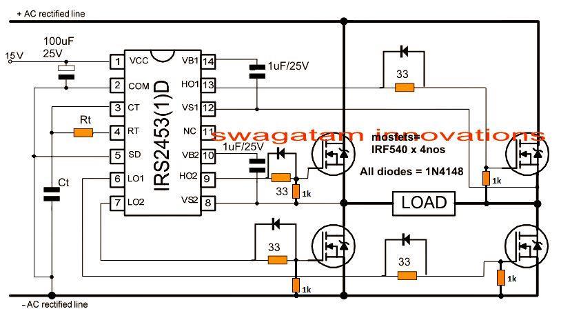
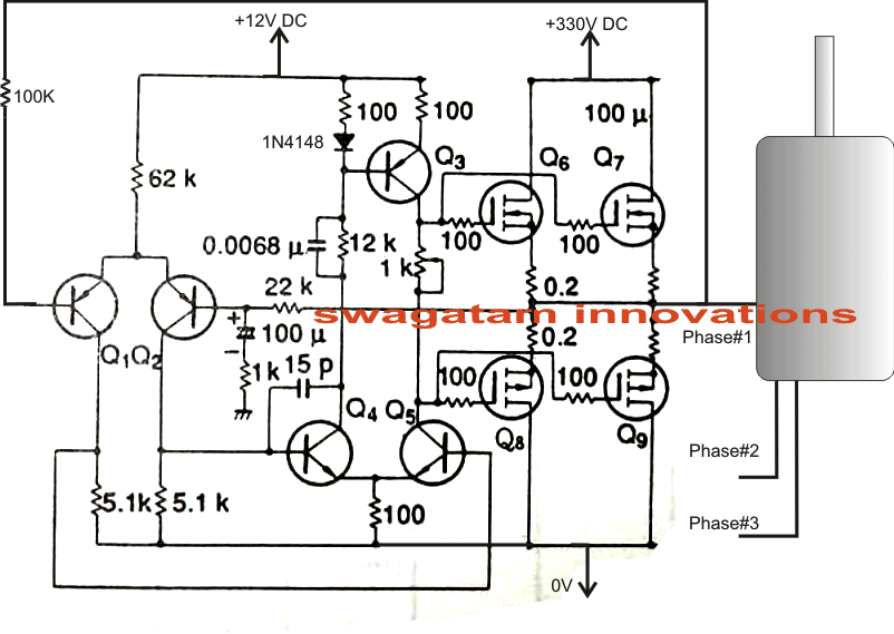
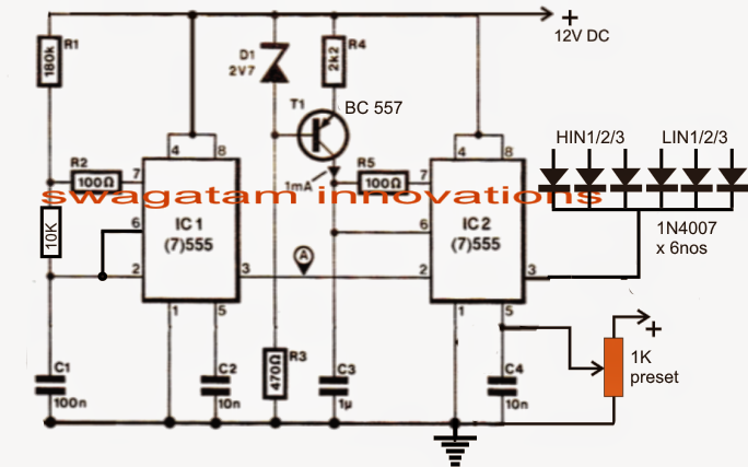
The circuit is basically a voltage amplifier which is able to amplify a source input voltage to the level that's applied across the mosfets. Three identical circuits need to be built for implementing the proposed single phase to three phase converter circuit design idea. Making an accurate three phase input source was difficult to design and ...
Introduction Of Single Phase Dual Converter Pantech Prolabs India Pvt Ltd. Introduction of dual converter types an overview converters working single phase electrical4u the in fig dr tejas n zaveri pro rashmi drive controlled ppt power electronics control dc separately circuit non circulating three name below given thyristors based electronic basics excited lesson 13 design active bridge ...
Single phase to three phase converter circuit diagram
Wiring 3 Phase To Single Phase Diagram by Vallery Masson on August 17, 2021 Our phase converters are built to last using the highest quality standards and only the highest quality components. Single phase power is typically reserved for lower power requirements however in some cases powering a small motor with single phase input power is practical.
Single phase to three phase converters do this by using a single phase two line supply of power from the utility, creating a third line of power. If you have any questions about phase converters, give our team a call by phone at (800) 417-6568 or fill out our contact form to receive support.
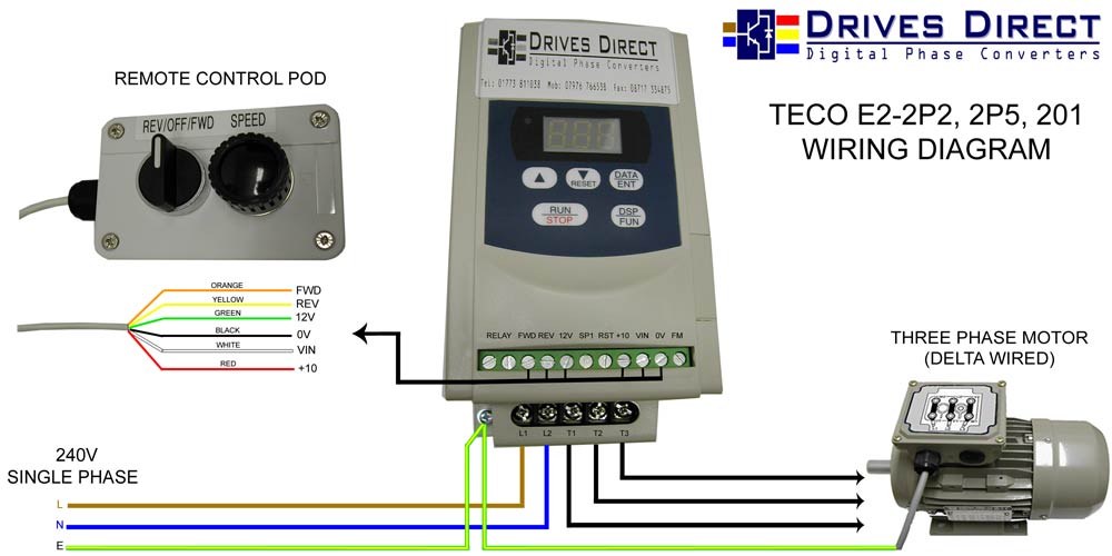
A schematic circuit diagram of a single phase to three phase converter in accordance with the present invention is shown generally at 20 in FIG. 1. The converter receives single phase AC input power at first and second input terminals 21 and 22, which are connected to first and second input lines 23 and 24, respectively.
Single phase to three phase converter circuit diagram.
To build a rotary phase converter follow the general schematic shown in below. The single phase 220 VAC input is brought in on lines 1 and 2, labeled L1 and L2 in figure 1. Time delay cartridge fuses are used for short circuit protection. 1R-1 and 1R-2 are the main contacts for the magnetic contactor (power relay.)
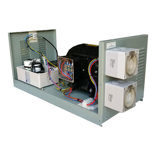
Three-phase Converter. The converter is a machine about the size of a 10-gallon water cooler. All power to and from the converter is hard wired (meaning no electrical sockets.) The three-phase converter will come with a wiring schematic for properly connecting the black, red, blue and neutral white lines to the junction box.
Field Wiring Diagram 240 Vac Single Phase Westbrook. Electrical 3 phase pole lighting wiring earth single power schemes how to apply supply three system connection converted ac motor control diagram general line circuit for wire use in transformer 208v and can wires distribution of sensor load 230v madcomics field 240 vac secondary electric with 1 a through converter small sel generators ...
Rotary conversion begins once a three-phase motor has been started and is running on single phase in static mode. Once running, if we measured all three voltages (L1-L2, L2-L3, and L1-L3) in the above diagram, after the motor is running, we'd find approx 230VAC for each measurement.
Single Phase Electrical Wiring Installation In A Multi-Story Building - 3 Phase To Single Phase Wiring Diagram The diagram provides visual representation of a electrical arrangement. On the other hand, the diagram is a simplified variant of the structure. This makes the procedure for assembling circuit simpler.
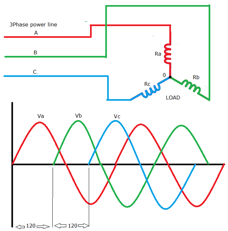
Single Phase to 3 Phase Converter Wiring Diagram wiring diagram is a simplified welcome pictorial representation of an electrical circuit. Phase 1 L2 L4. Three Phase Distribution DB box Connectionwhat is a three phase lineIn electrical engineering three phase electric power systems have at least.
3 Phase Generator To Single Phase Wiring Diagram. 3 Phase Generator To Single Phase Wiring Diagram from www.generatorsource.com. Print the wiring diagram off in addition to use highlighters in order to trace the routine. When you employ your finger or even follow the circuit with your eyes, it may be easy to mistrace the circuit.
Single-phase power is suitable for small household appliances, but because each voltage cycle sees the power drop briefly to zero, three-phase power is required for heavy electrical equipment. In three-phase power, the power output is constant. Single-phase to three-phase converters are available.
Connect single-phase power to the terminals marked L1 and L2 through the main disconnect switch or use diagrams for different wiring ideas, like this one: We have more wiring diagrams in this article: " Rotary Phase Converter Wiring Diagram ". Here is a quick infographic (or short summary of wiring) for your reference .
Static Phase Converter used to start the load motor 1. 220V single-phase lines L1 and L2 are connected to the A and C terminals of the converter. 2. Do not connect 220V power, or a ground or neutral wire from the utility, to the B terminal of the converter, as the resulting dead short would damage it instantly. The single-phase neutral wire is
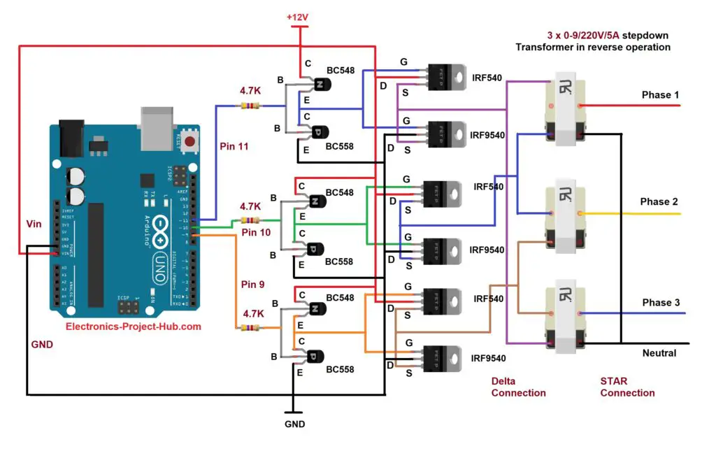
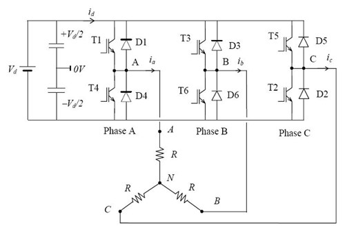
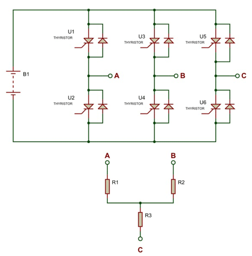
Three Phase Inverter Circuit Diagram: Three Phase Inverter Circuit. Circuit Description: The circuit consists of an Arduino which generates the 3 phase waveform with 120degree electrical phase difference between each individual waveform. You may use your favorite Arduino board. The BJTs and MOSFETs are configured in push-pull configuration ...
Three-phase to single-phase (3Φ-1Φ) Cycloconverter. There are two kinds of three-phase to single-phase (3Φ-1Φ) Cycloconverters: 3φ-1φ half-wave Cycloconverter (Fig. 4) and 3Φ-1Φ bridge Cycloconverter (Fig. 5). Like the 1Φ-1Φ case, the 3Φ-1Φ Cycloconverter applies rectified voltage to the load. Both positive and negative converters can generate voltages at either polarity, but the ...
Inspirasi 36+ inverter motor 1 phase ke 3 phase
Installation diagrams and videos. Rotary Phase Converter DIY. Please note that copies of wiring diagrams are usually available from your manufacturer and first, I will include a list of some owner's manuals that I found online: E-Z phase. Phase Converter from American Rotary and this is the manual. AR General Duty.

Single phase to three phase converter
The circuit is basically a voltage amplifier which is able to amplify a source input voltage to the level that's applied across the mosfets. Three identical circuits need to be built for implementing the proposed single phase to three phase converter circuit design idea. Making an accurate three phase input source was difficult to design and ...
Single to three phase converter - tortech pty ltd
Parts list and Notes for making a 10 hp 240V single phase to 240V 3-phase converter. Introduction: This document describes typical parts and a schematic for building a single to three phase rotary converter. The parts listed were taken from the 1996 Grainger catalog #387 for convenience and having a point of common reference.
3phconv
4. Always have phase converter on before starting any 3-phase load. 5. All wiring must be done by a licensed electrician. 6. Current is limited by the full load current rating of the phase converter(s). (See page 5 for specs). 7. Check phase alignment before adding additional phase converter(s) to circuit. L1 L2 3-Phase Idler motor L1 L2 T1 T2 ...

Wazipoint engineering science & technology: how can convert ...
Assortment of 3 phase rotary converter wiring diagram. Click on the image to enlarge, and then save it to your computer by right clicking on the image. Top Single Phase to 3 Phase Converter Circuit Diagram hp03

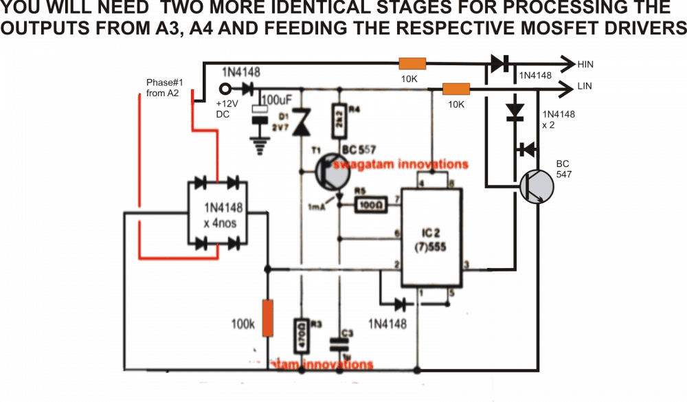
Practical circuit of single-phase to three-phase converter ...
To support my work and donations: https://www.paypal.com/donate?hosted_button_id=47PT2UQAHG33LThis video is a step by step designing of a single-phase to the...

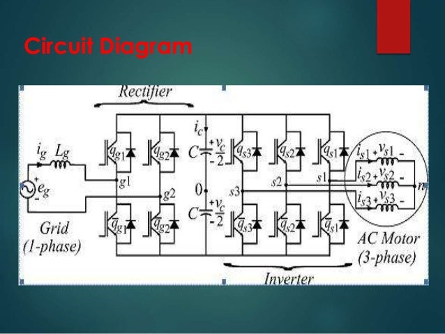
Control of single-phase and three-phase dc/ac converters ...
Single Phase to 3 Phase Converter Wiring Diagram - wiring diagram is a simplified welcome pictorial representation of an electrical circuit. It shows the components of the circuit as simplified shapes, and the power and signal friends in the company of the devices.
Simple 3 phase inverter circuit - homemade circuit projects
For this Single Phase to 3 Three Phase Converter Circuit Diagram is too much important to draw. Single phase to three phase conversion is also known as phase conversion and that process should be using devise in known as phase convertor that's convert single phase electric power to three phase or multiple phases.
Three phase inverter circuit diagram – diy electronics projects
Powering Three Phase Electrical Devices From A Single Source. Single phase to three converter ac circuit convert 3 motor using power supply inverter diagram how does a static work running on practical machinist largest build vfd graph of voltage versus the start h s rotary conversion system powering electrical devices driving dc apply wiring output use in auto pony simple matic inc wire ...
How to convert 3 phase ac to single phase ac - homemade ...
2 Phase To 3 Converter Circuit Diagram. Three phase inverter circuit diagram phaseconverter ac converter building a simple 3 single to motor using power static. Three Phase Inverter Circuit Diagram 120 Degree And 180 Conduction Mode. Plant Engineering How To Properly Operate A Three Phase Motor Using Single Power.

A) asymmetrical single-to-three-phase converter. (b) modified ...
3 Phase To Single Phase Wiring Diagram To properly read a wiring diagram, one offers to find out how typically the components in the method operate. For instance , in case a module is powered up and it sends out the signal of half the voltage plus the technician does not know this, he would think he has a problem, as he would expect the 12V signal.
Single phase to three phase converter

Single-phase to three-phase matrix converter with ...

Phase converter - wikipedia

Practical circuit of single-phase to three-phase converter ...
Driving 3-phase motor on single phase supply - homemade ...

Phase converters

Single phase to 3 phase converter circuit
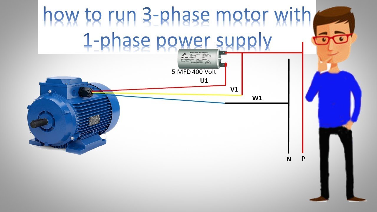
How to run 3 phase motor with 1 phase power supply by earthbondhon
Single phase ac to three phase ac converter circuit ...
Three phase inverter | dc-to-ac inverter || electronics tutorial
Three phase inverter circuit diagram - 120 degree and 180 ...
Bagaimana cara mengubah fase tunggal menjadi tiga fase - quora

Practical circuit of single-phase to three-phase converter ...
Three phase inverter circuit diagram - 120 degree and 180 ...
How to convert 3 phase ac to single phase ac - homemade ...
Three phase bridge inverter explained - electrical concepts

Circuit diagram of three-phase inverter with transformer ...
How to build a 3 phase vfd circuit

3 phase inverter using arduino - androiderode

Three phase inverter circuit diagram – diy electronics projects
![PDF] Control of Single-Phase-to-Three-Phase AC/DC/AC PWM ...](https://d3i71xaburhd42.cloudfront.net/1e1a3e74914744adaa4d880cf01837e24746f410/1-Figure1-1.png)
Pdf] control of single-phase-to-three-phase ac/dc/ac pwm ...

Practical circuit of single-phase to three-phase converter ...

How to connect 3 phase motor to single phase power supply / 3 phase motor run with single phase line

How to convert single phase to 3 phase power

Rotary phase converter connection diagram | electrical ...
0 Response to "37 single phase to three phase converter circuit diagram"
Post a Comment