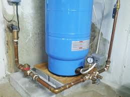
37 well pressure tank installation diagram
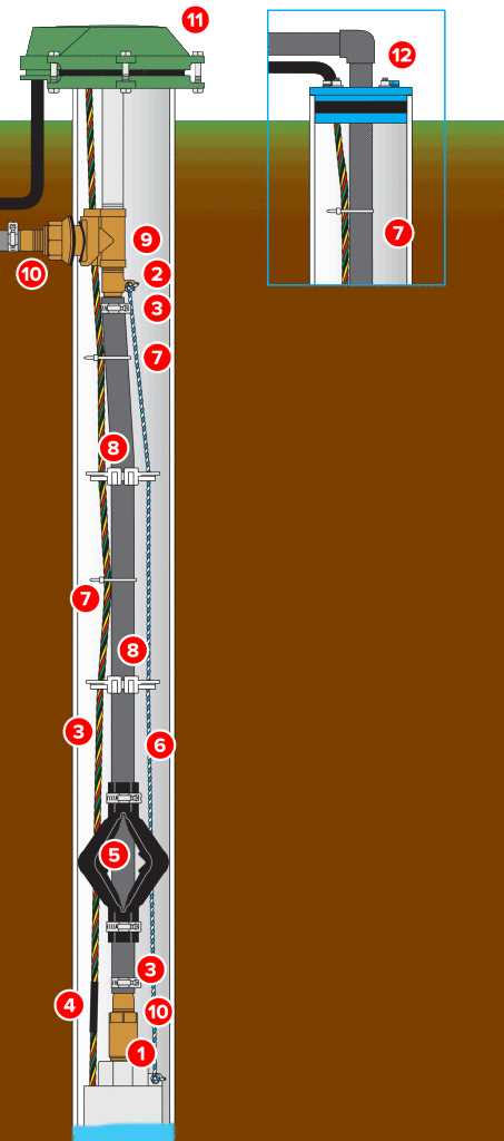
STEP 5 Install a sanitary well seal onto the top of the 1 1/4" suction pipe to fit well diameter. Use 1 1/4" tee and a 1 1/4" plug at the top of the well seal to support suction pipe in the well. Install 1 1/4" union between well and 1" pressure pipe that will rest on the well seal to support the pipes and ejector or jet in well. INSTALLATION MANUAL FOR HORIZONTAL WELL SYSTEM TANKS Models HT6HB, HT14HB and HT20HB Keep this manual with the tank for future reference. Part #: 9015-377 (01/19) What You'll Need Before You Start Always be sure to equip your well system with a proper Pressure Relief Valve. This should be capable of discharging the full output of
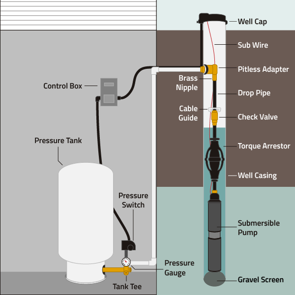
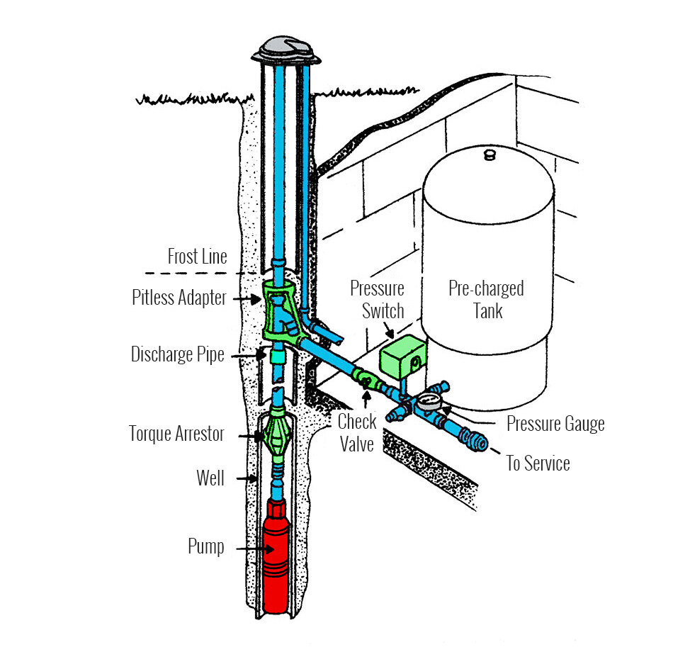
To complete installation, you will require the following: • Submersible pump sub pac which includes pressure switch, pressure gauge, service tee, relief valve, sub cable and built-in check valve • Pressure tank • Torque arrestor • Well seal or pitless adaptor • 1" discharge piping HOTLINE 888.956.0000 www.RedLionProducts.com
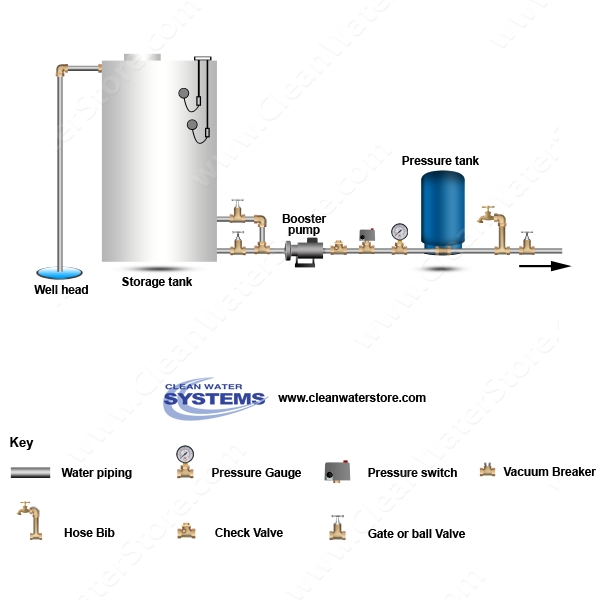
Well pressure tank installation diagram
Water Well Pressure Tanks. As water is pumped from the well into the pressure tank, it compresses the air in the tank until it reaches a preset level, typically the 40 to 60 pounds per square inch (psi). When someone turns on a faucet, air pressure in the tank forces water throughout the plumbing until the pressure drops to the preset trigger ... Check Valve. Installed near the tank inlet to hold water in the tank during pump installation when the pump is idle. 8. Tank Tee. Connets water line from pump ... Pressure Pressure Switch How a Well Tank Works 1. As the pump fills the tank with water, the air above the diaphragm is compressed. This increases the pressure in the tank and causes the pressure switch to turn off the pump. 2. When water is used, it is drawn from the tank and the pressure inside the tank decreases. The reduced pressure
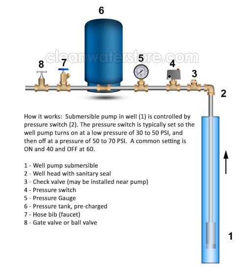
Well pressure tank installation diagram. Water Pressure Tank Installation Diagram. The image below shows the typical installation diagram of a well pressure tank, as well as other components of a well system. Image: Lakeland Water Pump How a Bladder Pressure Tank Works. A bladder pressure tank is a steel tank with a bladder inside which looks like a balloon. tank. The complete pump, tank, pressure relief valve, pressure switch and piping system MUST be protected against below freezing temperature. Failure to do so could cause the tank to explode and result in DEATH, SERIOUS BODILY INJURY, OR PROPERTY DAMAGE. The well tanks are designed for operation on water systems with TYPICAL SUBMERSIBLE PUMP INSTALLATION 1. We recommend the captive-air style pressure tank. It has significantly higher drawdown than a standard pressure tank and eliminates water logging problems. The air level in the tank should be 2 lbs. less than pressure switch turn-on level. For a 30-50 switch, this would be 28 lbs. of air with the tank ... This happens over a 20 psi range. The pressure is stored in the pressure tank - typically 84 or 116 gallons. If the system builds too much pressure, the relief valve will release the excess pressure to prevent the pump from being damaged. If the well produces less water than your water demand over a period of time and the well temporarily ...
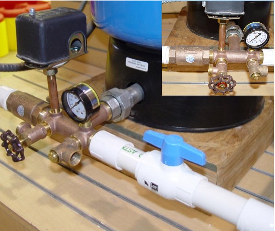
installed near the tank inlet holds water in the tank when the pump is idle. TANK TEE (Section O) Connects water line from pump to pressure tank and service line from tank to house. Taps are provided to accept Pressure Switch, Pressure Gauge, Drain Valve, Relief Valve, Snifter Valve, etc. DRAIN VALVE (Section H) For easy draining of the system. The tee, what your instructions call a tank cross unit, incorporates threaded fittings and tappings to accept all of the necessary connections to the water pressure tank: the pressure control switch, pressure relief valve, water inlet from the well, water outlet to the building, a tank drain, and in some cases, a shutoff valve for the line ... PRESSURE TANK INSTALLATION /BLADDER TANK INSTALLATION DIAGRAM. 8,036 views8K views ... How To Set Well Pressure Tank Air Pressure. The pump tank has been shipped with a factory precharge as indicated on the tank label. If your pump start-up pressure is different from the factory precharge, adjust the tank pressure with the empty tank to your pump start-up pressure. This can be accomplished by simply bleeding air from valve in the top of the tank with an accurate pressure ...
Pressure Tank Installation and Operating Instructions Rules for Safe Operation This is a diaphragm type pressure tank for use on a cold, well water system. The system must be protected by a suitable relief valve. Warning: failure to install a relief valve may result in tank explosion in the event of a system correct method of installing and operating your GWS pressure tank. ... FlowThru™ Series tanks are designed for use in well water or. Well Diagram. The quality water system products described here and illustrated are some of the Baker Water Systems products used in a typical well system. This list and the illustration are not intended as an installation guide. ... Connects water line from pump to pressure tank and service line from tank to house. Taps are provided to accept ... 6. Well Seal. Provides a positive seal inside the casing in above-ground installations. 7. Check Valve. Installed near the tank inlet to hold water in the tank during pump installation when the pump is idle. 8. Tank Tee. Connects water line from the pump to pressure tank and service line from tank to house.
Tank Tee Packages in Brass or Stainless Steel are designed to connect your pressure tank to your water line. Each package comes with a tank tee, full port ball valve, check valve, hose bib, 100 PSI pressure relief valve, male adapter (to connect to your incoming well line), pressure gauge, and a Square-D pressure switch with a choice of pressure settings.

Well Pressure Tank Installation Diagram. installation manual diaphragm well tank water heaters installation manual diaphragm well tank typical jet pump installation pressure gauge pp100g into right 1 4" hole of tank cross installation manual diaphragm well tank after installation be sure the pressure switch is set low enough to shut the pump off the well tanks are designed for operation on ...

Pressure Pressure Switch How a Well Tank Works 1. As the pump fills the tank with water, the air above the diaphragm is compressed. This increases the pressure in the tank and causes the pressure switch to turn off the pump. 2. When water is used, it is drawn from the tank and the pressure inside the tank decreases. The reduced pressure starts the
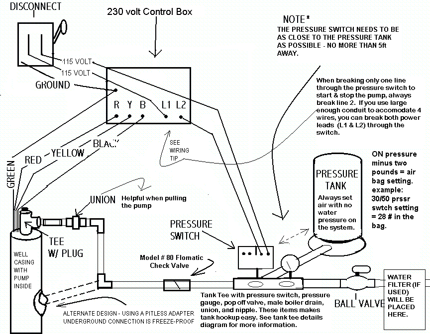
The tank pressure must be set 2 PSI lower than the pump cut-on pressure. Check tank pressure with a standard air gauge at the top of the tank as needed. ˆ$˘(2 ())'&(Where space is a critical factor, the in-line tank may be used or the <ˆ ˛ ˘ ˘ ˇ Various installations are shown. Also, to increase tank capacity up

6. Install the pressure relief valve in the other female threaded opening on the front of the cross bar of the tank. (Fig. 14) Always be sure to equip your well system with a proper pressure relief valve. Step III: Install the new tank cross assembly on the new tank. 1. Remove the plastic plug from the elbow at the bottom of the tank.
Diagrams --Typical Pump Installations. The information provided here is for educational purposes only. Technically qualified personnel should install pumps and motors. We recommend that a licensed contractor install all new systems and replace existing pumps and motors. Failure to install in compliance with local and national codes and ...
This well pressure tank installation video shows the steps you'll need for this replacement. Be sure to follow the proper requirements listed below and in th...
Conventional Pump & Pressure Tank Installation Diagram (Pitless Adapter). AWESOME DEALS!!! FREE SHIPPING on any order over $500.00 (Contiguous U.S. Only) ...

Well pump pressure tank diagram. Diaphragm well tank safety instructions installation warranty vertical series. For example if the well uses a ...

2. Install tank as close as possible to the pump pressure switch to reduce friction loss and elevation difference between the tank, water supply main, and switch. 3. After installation, be sure the pressure switch is set low enough to shut the pump off. If all valves are closed and the pressure switch
For example, if the well uses a pressure tank, a water treatment system must be installed after the pressure tank to avoid causing damage to the well pump. When you open a faucet in your home or turn on the shower or bath you expect water to flow at a certain flow rate and with good water pressure.

Installed near the tank inlet to hold water in the tank during pump installation when the pump is idle. (14) Tank Tee Connects water line from pump to pressure tank and service line from tank to house. Taps are provided to accept Pressure Switch, Pressure Gauge, Drain Valve, Relief Valve, Snifter Valve, etc. (15) Drain Valve

well Pressure Tank install DIY, A how to install a well pump pressure tank.diy plumbing, cheap, tips, and tricks. Replace a deep well pressure tank installed...

Well Diagram. The quality water system products described here and illustrated on the front page are some of the Baker Water Systems products used in a typical well system. (The section in the catalog where these items can be found is located in parentheses) This list and the illustration on the front page are not intended as an installation guide.

TYPICAL SHALLOW WELL JET PUMP INSTALLATION 1. Shallow well jet systems can be used when the depth of the water is no more than 20'. Water depths of more than 20' but less than 80' deep would use a deep well jet system or submersible pump. A submersible pump can also be used in shallow wells. 2. We recommend a captive air pump tank.

The proper installation, use, and servicing of this well tank is extremely important to ... A pressure relief valve must be installed in the piping adjacent.
Pressure Pressure Switch How a Well Tank Works 1. As the pump fills the tank with water, the air above the diaphragm is compressed. This increases the pressure in the tank and causes the pressure switch to turn off the pump. 2. When water is used, it is drawn from the tank and the pressure inside the tank decreases. The reduced pressure

Check Valve. Installed near the tank inlet to hold water in the tank during pump installation when the pump is idle. 8. Tank Tee. Connets water line from pump ...
Water Well Pressure Tanks. As water is pumped from the well into the pressure tank, it compresses the air in the tank until it reaches a preset level, typically the 40 to 60 pounds per square inch (psi). When someone turns on a faucet, air pressure in the tank forces water throughout the plumbing until the pressure drops to the preset trigger ...


0 Response to "37 well pressure tank installation diagram"
Post a Comment