38 acme buck boost transformer wiring diagram
Four-wire wye configurations will require three buck-boost transformers; 3-wire wye configurations will need two buck-boost transformers. Single-phase buck-boost transformer connection diagram Figure 1 below shows an example of an electrical connection diagram that illustrates the connection configuration for single-phase power to boost and ...
BUCK & BOOST TRANSFORMER INSTALLATION INSTRUCTIONS Ste)!s for Selecting the Proper Buck-Boost Transformer First, you should han· 1his i11lor111a1io11 hdorc selecting a huck-hoos1 1ra11sl1m11cr. Line Voltage-The vohagc 1ha1 you wa111 10 buck (decrease) or hoos1 (increase). This can he found hy mc;Lsuring the supply line vohagc with a vol1mc1er.
Collection of buck boost transformer wiring diagram. A wiring diagram is a streamlined standard pictorial depiction of an electrical circuit. It shows the elements of the circuit as streamlined shapes, and the power and signal links in between the devices.

Acme buck boost transformer wiring diagram
Buck Boost Transformer 208 to 240 Wiring Diagram Sample. buck boost transformer 208 to 240 wiring diagram - A Novice s Overview to Circuit Diagrams An initial appearance at a circuit layout could be complex, but if you can read a metro map, you could read schematics. The function is the exact same: obtaining from factor A to aim…
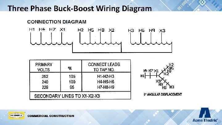
wire Y, use three buck-boost transformers. If the 3-phase supply is 3 wire Y (neutral not available), use two buck-boost transformers. Alternatively, Acme Electric's NEW 3 Phase Auto Buck Boost Transformers remove the need for multiple separate units and provide the same great electrical advantages standard Buck Boost Transformers offer in ...
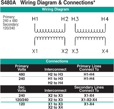
Buck-Boost Transformer Installation Sheet Revised on April, 2011 by T.E. If you are using this unit as an isolation transformer with a primary of 120 or 240 or 480 volts and the secondary of 12/24, 16/32, or 24/48 (depending on the model) use the wiring diagram located on the inside of the cover to the wiring compartment.
Acme buck boost transformer wiring diagram.
Boost Transformer Wiring Diagram Find Out Here Acme Buck Boost Transformer Wiring Diagram Sample. Boost Transformer Wiring Diagram- wiring diagram is a simplified customary pictorial representation of an electrical circuit. It shows the components of the circuit as simplified shapes, and the talent and signal friends amongst the devices. ...
Buck and Boost Dry-Type Transformers How to Select the Proper Transformer To select the proper transformer for Buck-Boost applications, determine: 1. Input line voltage: The voltage that you want to buck (decrease) or boost (increase). This can be found by measuring the supply line voltage with a voltmeter. 2.
Acme buck boost transformer wiring diagram - Architectural electrical wiring layouts reveal the approximate locations and also interconnections of receptacles lights and also long-term electric services in a building. Assortment of acme transformer t 1 81051 wiring diagram. A wiring diagram is a simplified traditional pictorial depiction of ...
Source: diagramproduct.today. Size: 364.58 KB. Dimension: 800 x 1036. DOWNLOAD. Wiring Diagram Images Detail: Name: acme transformer t 1 81051 wiring diagram - 25 kva transformer 1000 acme 120v to 240v buck boost 208 230 for rh teenwolfonline org Acme Transformer T 1 Acme Transformer Tech Support. File Type: JPG.
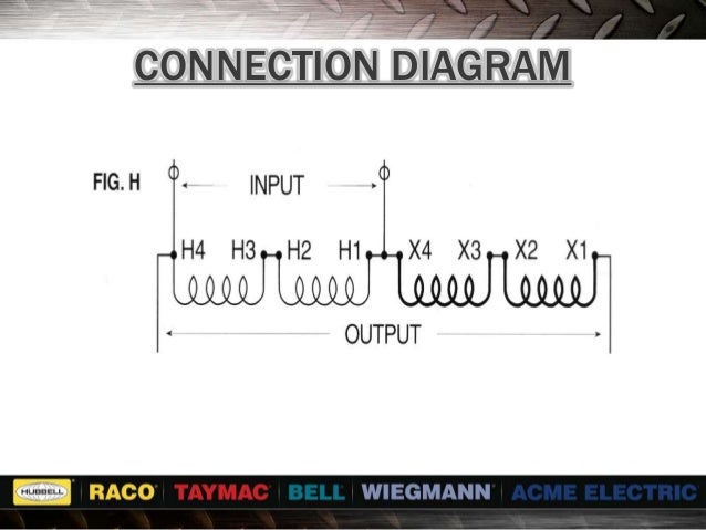
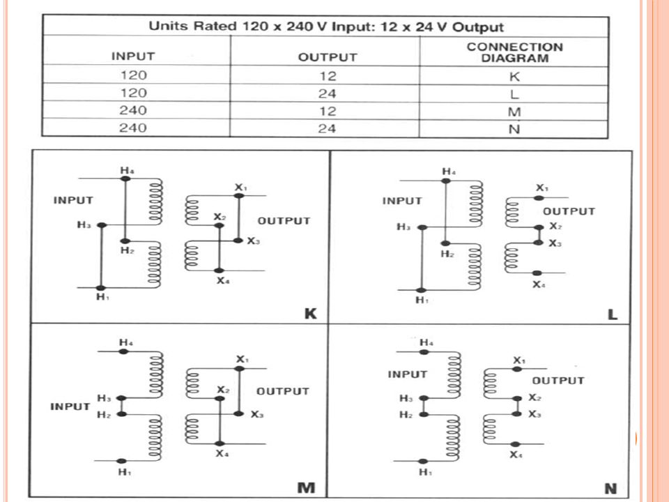
Review our Single Phase Buck Boost Wiring Tutorial for figure I in our Acme Electric catalog.
Buck-Boost Transformer - Single Phase, 120 X 240 - 12/24V, 500VA
Acme Electric T181058 Buck-Boost Transformer, 1 Phase, 60 Hz, 0.5 kVA, 120V x 240V Primary Volts, 16V/32V Secondary Volts 4.0 out of 5 stars 11 4 offers from $135.42
Buck-Boost Transformer Installation Sheet Revised on April, by T.E. If you are using this unit as an isolation transformer with a primary of or or volts and the secondary of 12/24, 16/32, or 24/48 (depending on the model) use the wiring diagram located on the inside of the cover to the wiring . SECTION7 BUCK-BOOST TRA NSFORMERS ACME ELECTRIC ...
BUCK AND BOOST TRANSFORMER INSTALLATION INSTRUCTIONS Steps for Sele ting the Proper Buck-Boost Transformer A-22498-G First, you should have this Information before selecting a buck-boost transformer. ' Line Voltage - The voltage that you want to buck (decrease) or boost (increase). This can be found by measuring the supply line
ENCAPSULATED SINGLE PHASE, .05 TO 10.0 KVA. Features: · UL Listed, CSA Certified and UL 3R enclosure, meets or exceeds all listing criteria, including NEMA, ANSI and OSHA standards · Flexibile - can be used in single phase and three phase configurations · Reduce (buck) or raise (boost) line voltage from 5-20% · All copper lead wire terminations · Long Life, 80° C rise up to 0.15 kVA, and ...
In Acme Buck Boost Transformer Wiring Diagram Within Just What's Wiring Diagram. A wiring diagram is a kind of schematic which makes use of abstract photographic icons to show all the interconnections of elements in a system. Wiring representations are made up of 2 things: icons that stand for the elements in the circuit, and lines that stand ...
Size: 46.70 KB. Dimension: 667 x 333. DOWNLOAD. Wiring Diagram Images Detail: Name: buck boost transformer 208 to 230 wiring diagram - Acme Buck Boost Transformer Wiring Diagram 3 Phase Buck Boost Transformer Wiring Diagram Wiring Diagram Schemes. File Type: JPG.

Practical machinist - largest manufacturing technology forum ...
on Buck Boost Transformer 208 To 240 Wiring Diagram. Wiring Diagrams. Buck-boost transformers are small single phase transformers designed to . Boosting V to V or V and vice versa for commer-. Steps for Selecting the Proper Buck-Boost Transformer . Units Rated x V Input: 24 x 48 V Output.

Jefferson electric—buck-boost transformers ...
NEC Handbook 2008 Exhibit 210.18 Typical single-phase connection diagrams for buck or boost transformers connected as autotransformers to change 240 volts single-phase to 208 volts and vice versa. Courtesy of NFPA, from 2008 Handbook
Boost low voltage - ecn electrical forums
Buck Boost Transformer Wiring Diagram - acme buck boost transformer wiring diagram, buck boost transformer circuit diagram, buck boost transformer wiring diagram, Every electric structure is composed of various distinct pieces. Each component should be placed and connected with different parts in particular manner. If not, the structure will not function as it ought to be.

6 buck boost transformers - pdf free download
ACME ELECTRIC † MILWAUKEE, WI † 800.334.5214 † acmepowerdist.com 157 GENERAL ELECTRICAL CONNECTION DIAGRAMSACME® TRANSFORMER™ WIRING DIAGRAMS PRIMARY: 240 Volts Delta SECONDARY: 208Y/120 Volts TAPS: 2, 5% BNFC X1 H1 X2 X3 H2 H3 X0 3 2 1 3 2 1 3 2 1 Connect Connect Primary Primary Inter- Secondary

Buck boost transformer
ACME ELECTRIC U MILWAUKEE, WI U 800.334.5214 U acmetransformer.com 125 GENERALGENERAL ELECTRICAL CONNECTION DIAGRAMSACME® TRANSFORMER™ WIRING DIAGRAMS PRIMARY: 240 Volts Delta SECONDARY: 208Y/120 Volts TAPS: 2, 5% BNFC X1 H1 X2 X3 H2 H3 X0 3 2 1 3 2 1 3 2 1 ConnectConnect Primary Primary Inter- Secondary
Buck-boost transformer installation sheet
BUCK-BOOST TRANSFORMER INSTALLATION SHEET 004-0921-000_0816 Buck-Boost Installation Sheet jeffersonelectric.com 1 of 4 If you are using this unit as an isolation transformer with a primary of 120 or 240 or 480 volts and the secondary of 12/24, 16/32, or 24/48 (depending on the model) use the wiring diagram located on the inside of the cover to the wiring
Steps for selecting the proper buck-boost transformer ...
3 Phase Buck Boost Transformer Wiring Diagram - wiring diagram is a simplified enjoyable pictorial representation of an electrical circuit. It shows the components of the circuit as simplified shapes, and the knack and signal associates with the devices. A wiring diagram usually gives assistance approximately the relative viewpoint and accord ...

T-1-81051-acme
Assortment of acme buck boost transformer wiring diagram. A wiring diagram is a simplified traditional pictorial representation of an electrical circuit. It reveals the components of the circuit as streamlined shapes, and also the power as well as signal connections between the gadgets.
File:swer.gif - wikipedia
Acme Buck Boost Transformer Wiring Diagram Collection. acme buck boost transformer wiring diagram - Architectural electrical wiring layouts reveal the approximate locations and also interconnections of receptacles, lights, and also long-term electric services in a building. Interconnecting cable routes could be shown approximately, where certain receptacles or components must get on a typical ...
Steps for selecting the proper buck-boost transformer ...
Hps Universal Single And Three Phase Potted Buck Boost Transformers Applications Standard Specification Pdf Free. Buck Boost Transformer Single Phase 120 X 240 16 32v 500va T181058 Acme Electric. Buck boost transformer 208 to 240 wiring diagram site resource steps for selecting the proper connection diagrams single phase 6 transformers pdf free ...

An overview of buck-boost transformer sizing - technical articles
Collection of acme buck boost transformer wiring diagram. A wiring diagram is a streamlined conventional photographic representation of an electric circuit. It reveals the elements of the circuit as simplified forms, and also the power and signal links between the devices.
Buck-boost transformer installation sheet
Buck-boost transformers group i selection charts

Buck boost transformer
Transformer seminar - buck-boost

I have a.75 kva federal pacific buck boost transformer trying ...
How does a buck-boost transformer differ from an insulating ...

Acme buck boost transformer wiring diagram - wiring site resource
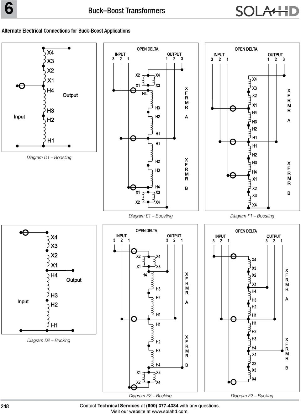
6 buck boost transformers - pdf free download

Acme electric t181052 buck-boost transformer, 1 phase, 60 hz, 0.75 kva, 120 x 240v input, 12/24v output, steel

Buck boost transformer

Acme buck boost transformer wiring diagram - wiring site resource

Acme t-1-81051 240 volt transformer 120

Buck boost transformers | mike holt's forum
Buck-boost transformer - single phase, 120 x 240 - 16/32v ...

Hubbell-acme electric single phase buck boost wiring demo- catalog figure i

This is an acme transformer 240-208 single phase i have to ...

Practical machinist - largest manufacturing technology forum ...
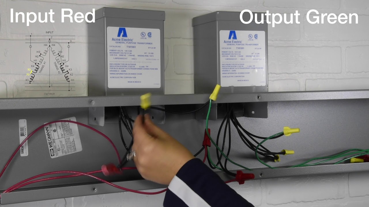
Acme electric- buck boost transformers- figure bb wiring demo
0.25 kva transformer primary 240x480 secondary 120/240 ...

Transformer seminar buckboost applications what are buckboost ...
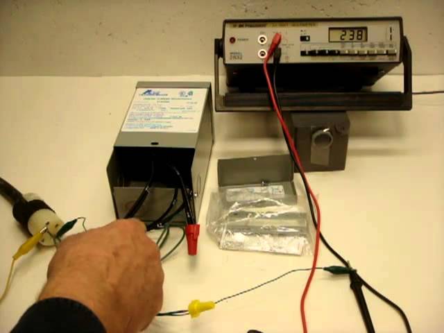
Acme buck boost transformer - youtube
Title- buck boost transformer by- neeraj s abhyankar seminar ...

Buck-boost transformers by mgm corrects off-standard voltages.

T111685 acme electric - distributors, price comparison, and ...
Transformer seminar buckboost applications what are buckboost ...
Buck-boost transformers
0 Response to "38 acme buck boost transformer wiring diagram"
Post a Comment