38 draw the shear diagram for the beam.
What are the SPCS83 coordinates (in ft) and convergenceangle for a station in the north zone of Pennsylvania with geodetic coordinatesof 41°12'33.0745" N and 76°23'48.9765" W?
Related Questions . XXXXXXXXXXDraw the influence lines for the shear and bending moment at point B and the shears just to the left and just to the right of support C of the beam shown in Fig. P8.12.
Diagrams 1; Diaphragm 2; direct analysis method 1; displacement 5; distribution 1; distribution load 1; Documentation 1; Drawing Adjustment 1; Drawing description 1; drawing identifications 1; Drawing numbers 1; Drawing Sheet 1; Drawing templates 1; Drawings 1; Drawings and Detailing 1; Drawings and Modelling 1; Ductility 1; dynamic 1; Dynamic ...
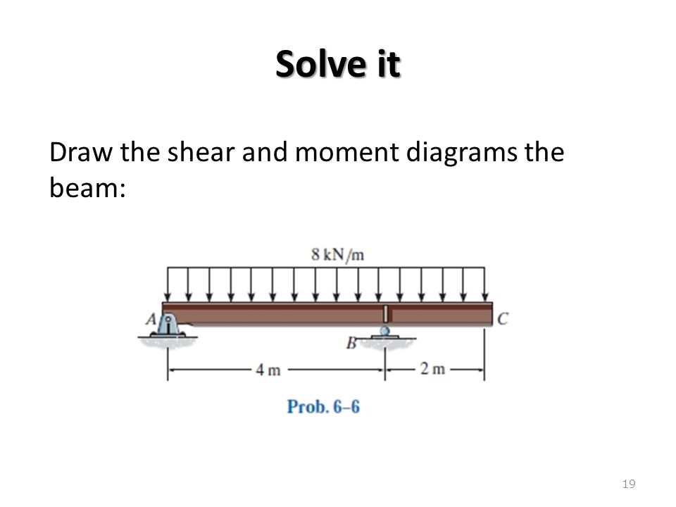
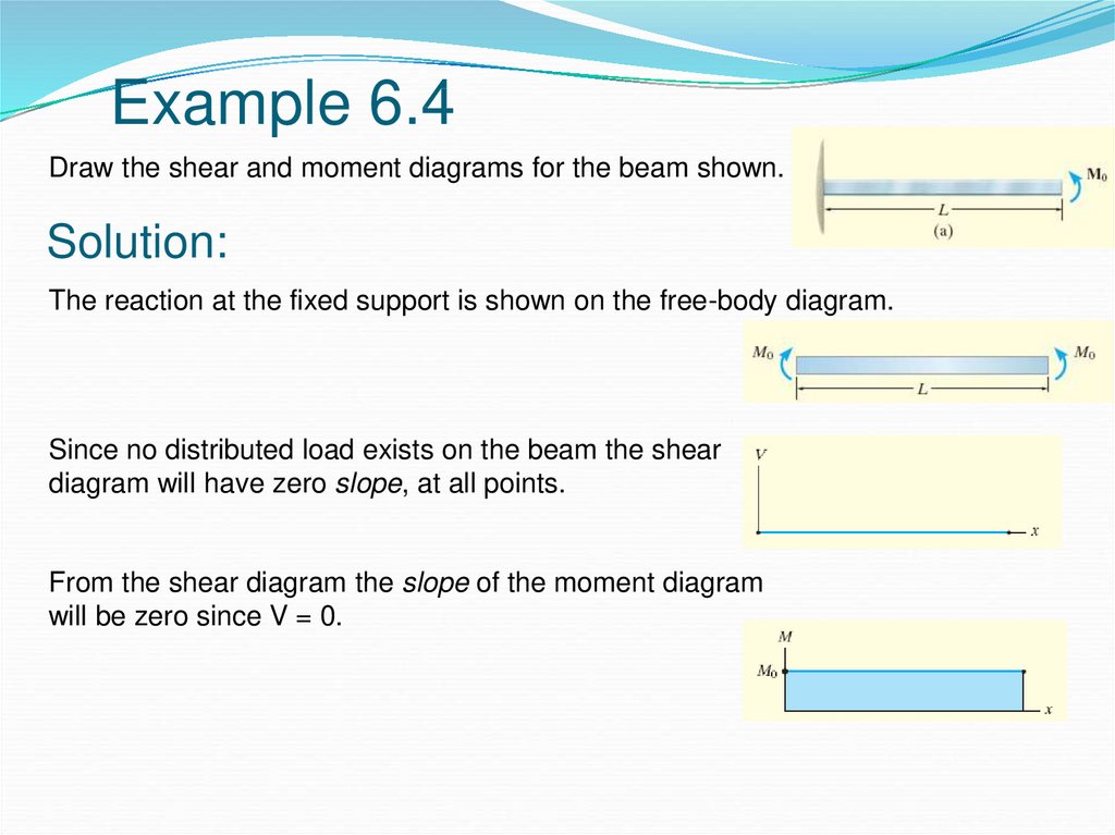
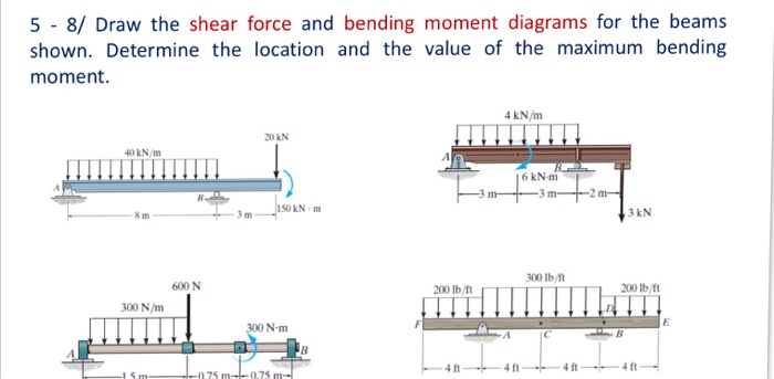
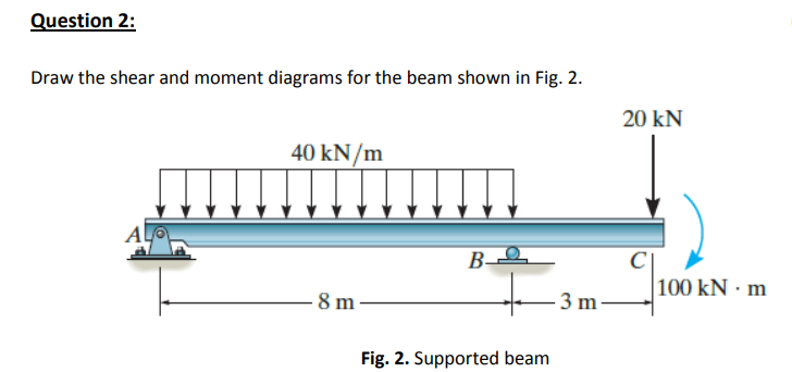
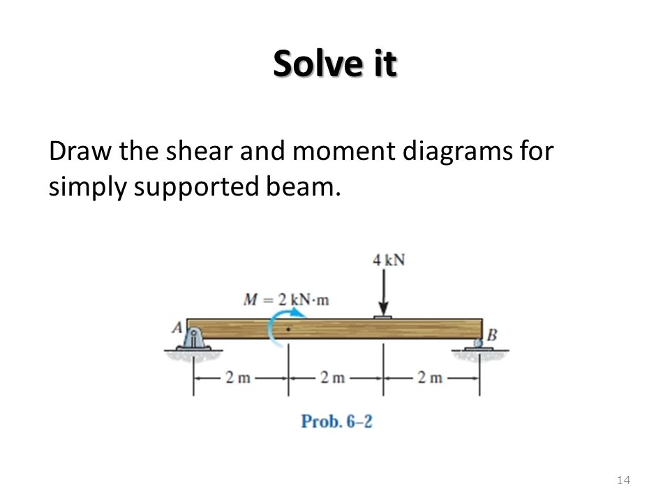
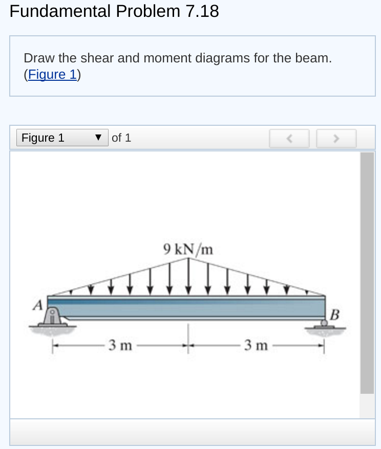
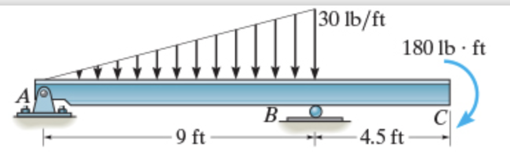
Draw the shear diagram for the beam.
The material behavior of asphalt depends on its composition of aggregate, bitumen, and air voids. Asphalt pavements consist of multiple layers, making the interaction of the materials at the layer boundary important so that any stresses that occur can be relieved. The material behavior at the layer boundary is not yet understood in detail, as further methods of analysis are lacking in addition ...
Alternative drawing convention — Shear and Bending moment diagram for a simply supported beam with a concentrated load at mid-span. Shear and bending moment ...
35 draw the shear diagram for the beam. 37 cub cadet parts diagrams catalog; 36 converging lens ray diagram simulation; 37 what is a diagram in science; 35 concave mirror ray diagram rules; 37 iron carbon phase diagram steel; 36 convex mirror ray diagram table; 39 electron transport chain diagram easy;
Draw the shear diagram for the beam..
Free online beam calculator for generating the reactions, calculating the deflection of a steel or wood beam, drawing the shear and moment diagrams for the beam ...
35 draw the shear diagram for the beam. 37 cub cadet parts diagrams catalog; 36 converging lens ray diagram simulation; 37 what is a diagram in science; 35 concave mirror ray diagram rules; 37 iron carbon phase diagram steel; 36 convex mirror ray diagram table; 39 electron transport chain diagram easy; 39 cub cadet parts diagrams rzt 42
Draw the shear force and bending moment diagram for this loading. 52. Page 6. 300. +. 1.20. Fig. 3-7 cantilever beam subjected to couple. Ans. The shearing ...
35 draw the shear diagram for the beam. 37 cub cadet parts diagrams catalog; 36 converging lens ray diagram simulation; 37 what is a diagram in science; 35 concave mirror ray diagram rules; 37 iron carbon phase diagram steel; 36 convex mirror ray diagram table; 39 electron transport chain diagram easy;
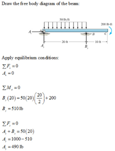
Draw the free body diagram for the beam. Step 2: Apply equilibrium equations. In X direction. ∑ FX = 0. ⇒ RAX = 0. In Y Direction.25 pages
35 draw the shear diagram for the beam. 37 cub cadet parts diagrams catalog; 36 converging lens ray diagram simulation; 37 what is a diagram in science; 35 concave mirror ray diagram rules; 37 iron carbon phase diagram steel; 36 convex mirror ray diagram table; 39 electron transport chain diagram easy; 39 cub cadet parts diagrams rzt 42
And (2) draw the shear force and bending moment diagrams. Neglect the weight of the beam. The support reactions A and C have been computed, and their values are ...42 pages
A beam ABC is simply supported at A and B and has anoverhang BC (see figure). The beam is loaded by two forces P and a clockwisecouple of moment Pa at D that act through the arrangement shown. (a) Draw the shear-force and bending-moment diagrams forbeam ABC.
You will be fully competent in drawing shear force and bending moment diagrams for statically determinate beams and ...Jul 23, 2021 · Uploaded by DegreeTutors
Free online beam calculator for generating the reactions, calculating the deflection of a steel or wood beam, drawing the shear and moment diagram s for the beam. This is the free version of our full SkyCiv Beam Software. This can be accessed under any of our Paid Accounts, which also includes a full structural analysis software.
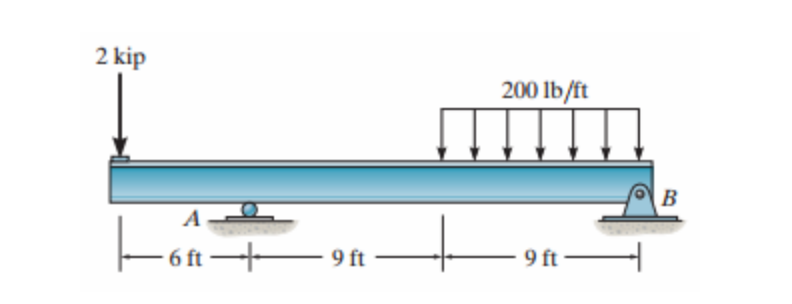
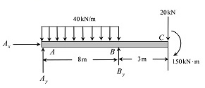
6–9. Draw the shear and moment diagrams for the beam. Hint: The 20-kip load must be replaced by equivalent loadings at point C on the axis of the beam.143 pages
Free online beam calculator for generating the reactions, calculating the deflection of a steel or wood beam, drawing the shear and moment diagrams for the beam. This is the free version of our full SkyCiv Beam Software. This can be accessed under any of our Paid Accounts, which also includes a full structural analysis software.
Solved draw the shear diagram for the beam. draw the moment ...
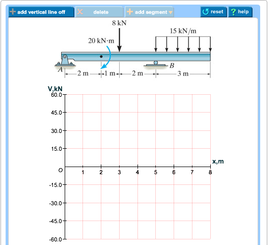
Transcribed image text: Problem 7.53 Part A Draw the shear diagram for the beam. Click on "add discontinuity" to add discontinuity lines.

Draw the shear diagram for beam | beams, bending moment ...
Dec 08, 2021 · The shear diagram of a beam is shown in the figure. Draw the shear diagram for the beam. 6.8.Place the appropriate function between the lines of discontinuity, ensuring the endpoints have the correct values. 1.6 2.4 (kn) 36 16 6. 6-9.
Solved problem 7.75 part a draw the shear | chegg.com
Solved draw the shear diagram for the beam. draw the moment ...

Part a draw the shear diagram for the beam. part b draw the ...
Draw the shear diagram for the beam. - studentshare

Statics 7.61 - draw the shear and moment diagrams for the beam.

For the figure below, draw the shear and moment diagrams for ...

Statics 7.71 - draw the shear and moment diagram for the beam ...
Hibbeler r.c. structural analysis
Solved draw the shear diagram for the beam. draw the | chegg.com
Answered: draw the shear diagram for the beam.… | bartleby
Draw the shear diagram for the beam - home work help - learn ...

Solved) - part a draw the shear diagram for the beam. part b ...
Bending shear and moment diagram, graphical method to ...

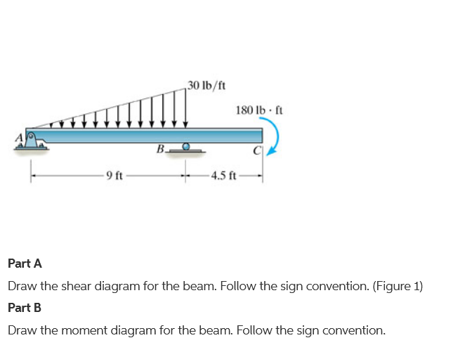
Draw the shear diagram for the beam. follow the sign ...

Drawing shear and moment diagrams for beam - youtube
Unit 6: bending\. shear and moment diagrams - online presentation

Draw the shear and moment diagrams for the cantilever beam in ...
Solved) - draw the shear force and bending moment diagrams ...
Answered: draw the shear and moment diagrams for… | bartleby
Solved] draw the shear force bending moment diagrams of the ...

Part a draw the shear diagram for the beam. follow the ...

Draw the shear diagram and the moment diagram for the beam ...

Please answer this question in one hour. problem 6.13 part a ...

Solved 7.78 draw the shear and moment diagram for the beam ...
Draw the shear diagram for the beam. draw the moment diagram ...
Can you draw the shear force and bending moment diagrams of ...

Draw shear and bending diagram for the beam given in the ...

Engineering mechanics statics pages 351 - 400 - flip pdf ...
Shear diagram - beam with 3 supports | physics forums
Bending shear and moment diagram, graphical method to ...
Solved) - draw the shear and moment diagrams for the beam ...

Draw the shear and moment diagrams for the compound beam ...
Answered: draw the shear diagram for the beam.… | bartleby

How to calculate and draw shear and bending moment diagrams ...

Drawing shear and moment diagrams for beam
0 Response to "38 draw the shear diagram for the beam."
Post a Comment