38 ford 6.0 diesel vacuum line diagram
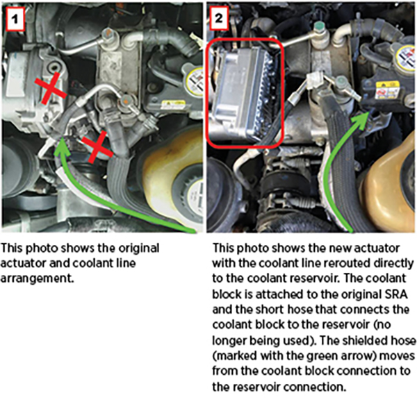
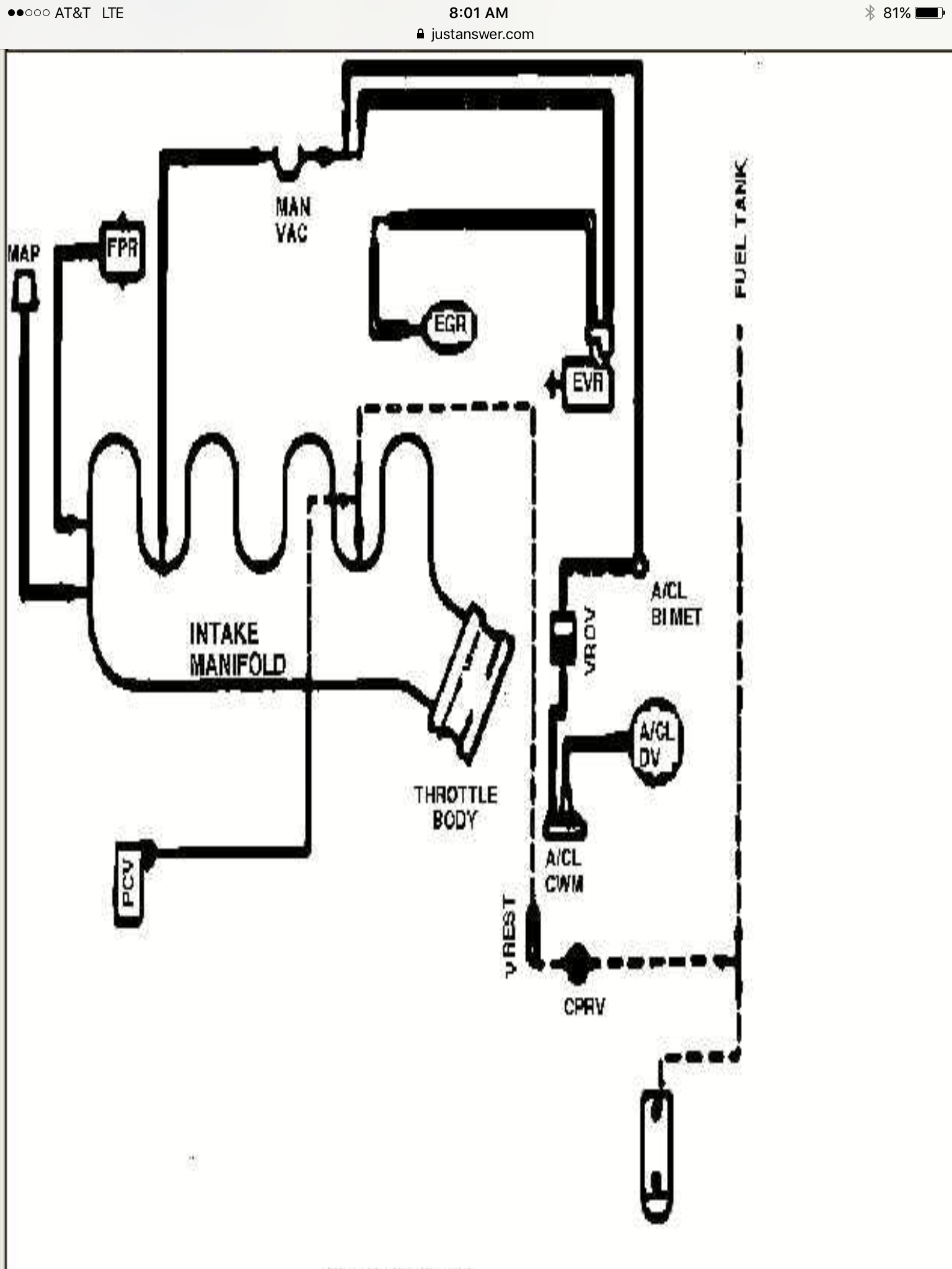
Hi got an 06 f250 6.0, im having problems with the vacuum lines, i have had the cab off to do heads and gaskets and i seem to misplaced a vacuum line i have one unhooked off of the vacuum reservoir, also only my defrost is blowing heat and front end is spinning in 2wd, i cant find a diagram anywhere and ive read up a little bit on why its blowing only through the defrost, what i need is a ... Bulletproof diesel does. Turns out it wasn't even the lines going to the hubs, found one of the plastic joint connections was snapped under the hood. Pulled the broken piece out and reinserted the line. Then had to unplug the pump electrical connector and replug it so it would kick on. The vacuum reservoir was obviously empty.
Apr 25, 2015 · Need diagram of the turbo hose location at the top of turbo. Your truck came with a 6.0 and a 7.3 so am not sure what you have or exactly what hoses you are talking about for sure. Below is a diagram of the complete turbo and hoses/ducts for a 7.3. I hope this is what you need and I hope this helps.

Ford 6.0 diesel vacuum line diagram
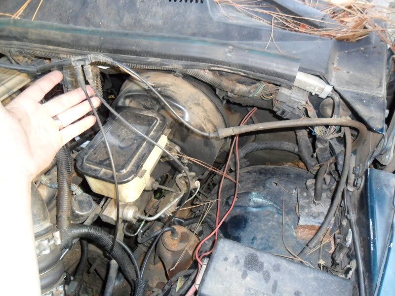
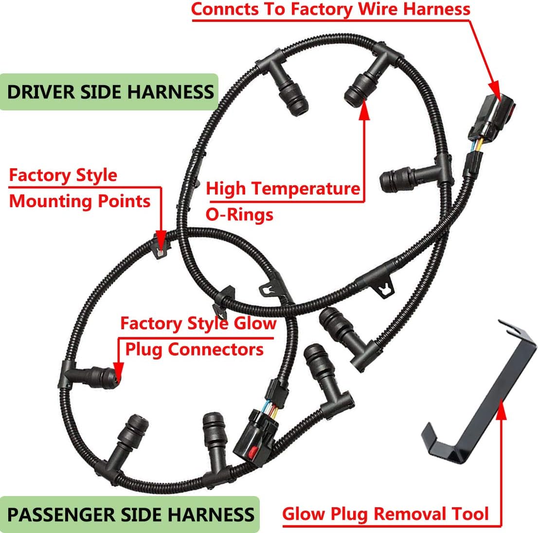
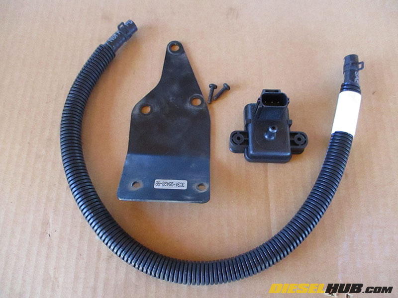
This picture shows the removed broken vacuum line fitting and new fitting I purchased for the repair. The new fitting is a 3/16" vacuum line connector fitting. Press the new fitting into the the vacuum line. Place the tube/fitting through the bracket. Press the hose from the hub on the other end of the vacuum line connector. Ford Truck Diagrams and Schematics. Alternator Voltage Regulator Instrument Panel Starter and Drive Distributor Jan 16, 2011 · Need vacuum diagram for '05 f350 6.0 diesel, squrrells got mine. from electric pump - Answered by a verified Ford Mechanic We use cookies to give you the best possible experience on our website. By continuing to use this site you consent to the use of cookies on your device as described in our cookie policy unless you have disabled them.
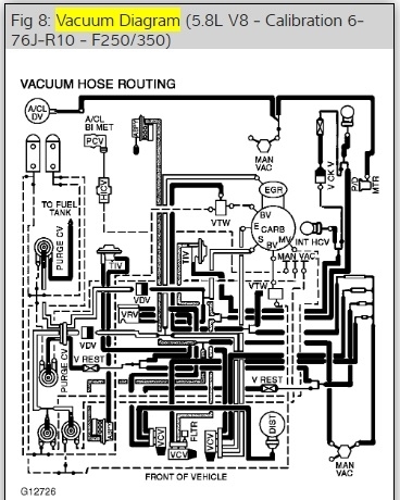
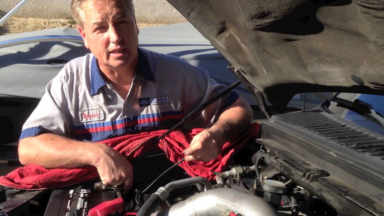
Ford 6.0 diesel vacuum line diagram. 6.0 Powerstroke Coolant Flow Diagram 12.12.2018 12.12.2018 2 Comments on 6.0 Powerstroke Coolant Flow Diagram The point is we get a lot of questions about L Ford Powerstroke engines Typically this happens from dirty coolant, improper cooling system. ford e350 vents stuck on defrost ford e350 vents stuck on defrost poolfixer loading how not to repair ford dash vacuum leak duration e350 rear ac fix [Page 06] 2004 ford e series van location of ac check valve hi ford not very forth ming with info but see diagram vacuum resivor tank under hood believe check vale attached to big hose leading to tank If your HVAC will only blow on defrost it may be due to a vacuum leak somewhere in the system. My truck is a 2006 6.0 Diesel, this vacuum layout may be vali... The 6.0L diesel engine is: • a four-cycle turbocharged V-8 with overhead valves. • 6.0 liter (365 cubic inch) displacement. • separated into 2 banks, the right bank numbered 1, 3, 5, 7 and the left bank numbered 2, 4, 6, 8. • rated at 325 horsepower and 570 lb-ft torque.
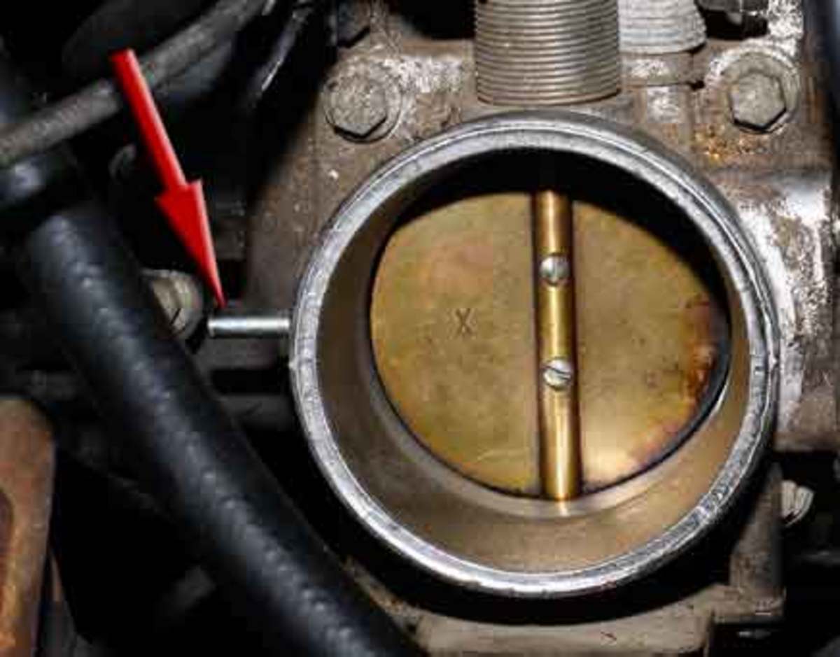
2) Single line to the pulse vacuum solenoid (one side of a double-line connector) C) From the solenoid (in the second side of the double-line connector) routing across the top of the canister, where there is a connector just before the line turns down beside the motor. This connection is a good test point. Down-stream (towards the wheels) can ... I have 84 & 85 Ford F250 4X4 w/ 6.9 diesel and they use a belt driven vacuum mounted below the alternator driven by a short belt from the alternator. Have never seen an OEM electric vacuum pump on any Ford F250 w/ 6.9 diesel and early 7.3 non powerstroke. This must be an after market unit, so look for marking or ID on it to find who made it. Jan 16, 2011 · Need vacuum diagram for '05 f350 6.0 diesel, squrrells got mine. from electric pump - Answered by a verified Ford Mechanic We use cookies to give you the best possible experience on our website. By continuing to use this site you consent to the use of cookies on your device as described in our cookie policy unless you have disabled them. Ford Truck Diagrams and Schematics. Alternator Voltage Regulator Instrument Panel Starter and Drive Distributor
This picture shows the removed broken vacuum line fitting and new fitting I purchased for the repair. The new fitting is a 3/16" vacuum line connector fitting. Press the new fitting into the the vacuum line. Place the tube/fitting through the bracket. Press the hose from the hub on the other end of the vacuum line connector.


0 Response to "38 ford 6.0 diesel vacuum line diagram"
Post a Comment