39 8 channel relay board circuit diagram
13 8 Channel Relay Board Circuit Diagram. A second type of electronic schematic diagram the pictorial layout diagram is actually not so much an electronic schematic as a pictorial of how the electronic circuit actually looks. Start a free trial today. This video is the clip of 8 channel relay circuit using transistor. 11 2 Channel Relay Board Circuit Diagram. 2 channel 5V 10A relay module Pin connectors Breadboard USB cable 1. Misuse can result in serious injuries. Connect the signal terminal IN1IN2 of 2-channel relay to digital 4 5 of the Arduino pin Uno or ATMega2560 board and connect an ...
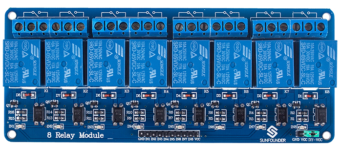
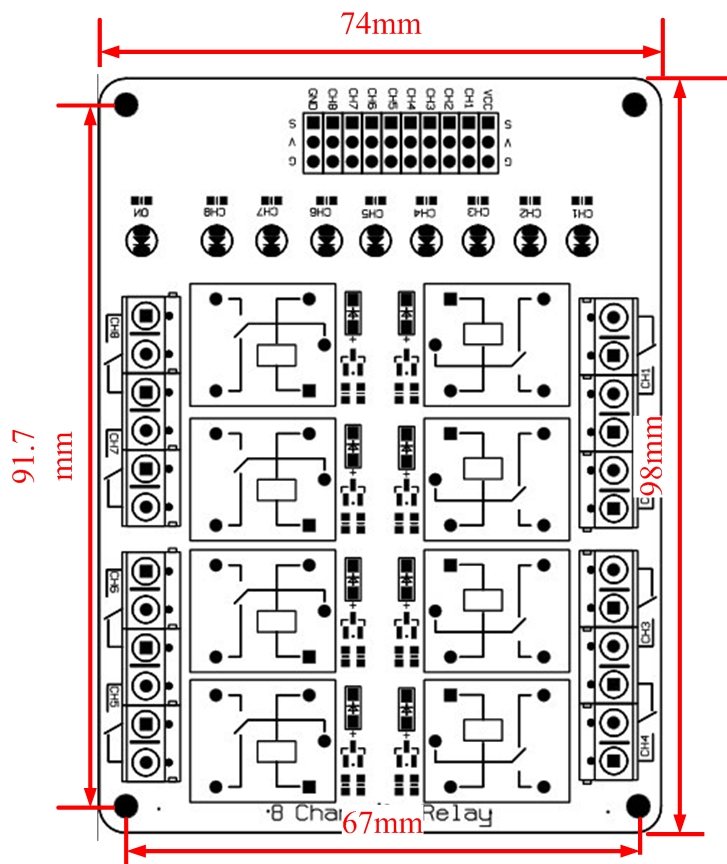
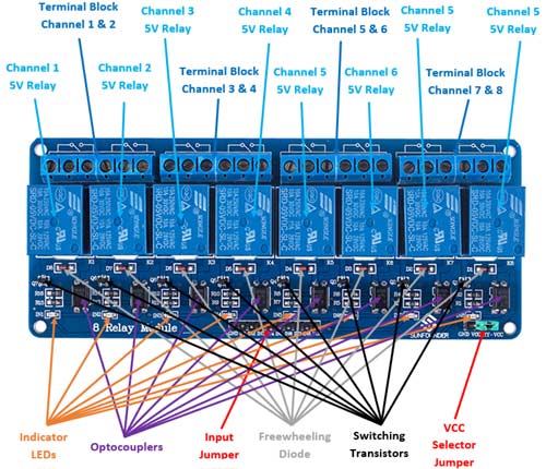
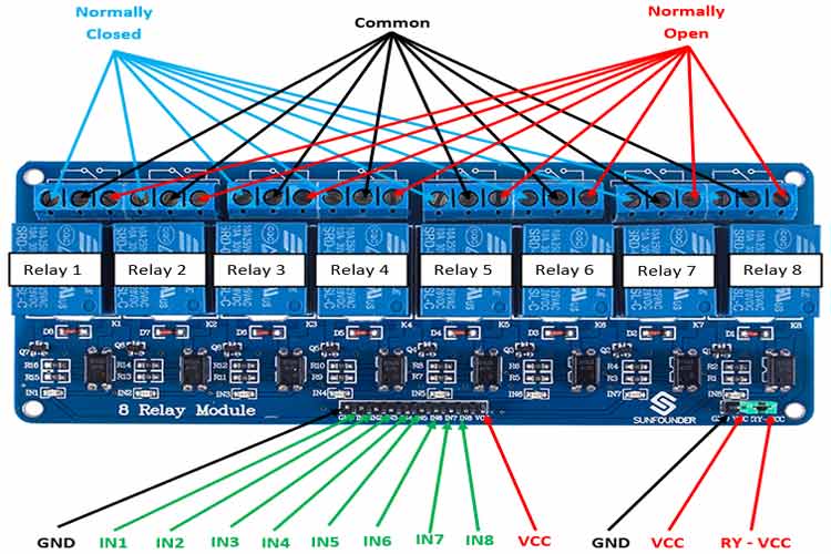
8 Channel 5V Optical Isolated Relay Module This is a LOW Level 5V 8-channel relay interface board, and each channel needs a 15-20mA driver current. It can be used to control various appliances and equipment with large current. It is equipped with high-current relays that work under AC250V 10A or DC30V 10A. It has

8 channel relay board circuit diagram
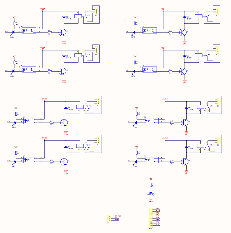
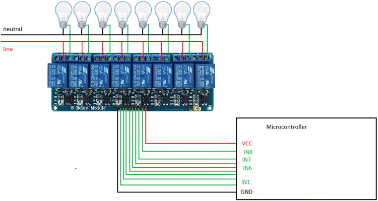
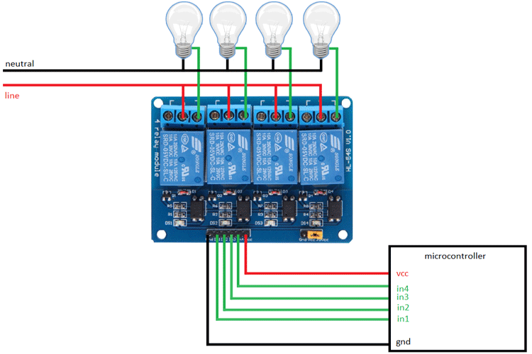
5V Relay Board 8 Channel Connections .. HELP ... Circuit Diagram. Voltage Divider. Measuring Instrument. Electronics Projects. Variables. Retro Fashion. Coding. Ps. DIY: Retro Style Analog Volt Meter using Servo Motor. Digital equipments have rapidly replaced Analog equipments in the long run. Well that is because the former has lot of ... Jan 18, 2021 · 5V 8-Channel Relay Module. The eight-channel relay module contains eight 5V relays and the associated switching and isolating components, which makes interfacing with a microcontroller or sensor easy with minimum components and connections. Each relay on the board has the same circuit, and the input ground is common to all eight channels. This is the complete circuit diagram for this home automation project. I have explained the circuit in the tutorial video. The circuit is very simple, I have used the GPIO pins D23, D22, D21, D19, D18, D5, D25 & D26 to control the 8 relays.. And the GPIO pins D13, D12, D14, D27, D33, D32, D15 & D4 connected with switches to control the 8 relays manually.
8 channel relay board circuit diagram. Sep 21, 2018 · Elegant Relay Module Wiring Diagram – Ipphil from 8 channel relay board circuit diagram , source:ipphil.com. So, if you’d like to receive all these awesome graphics related to (8 Channel Relay Board Circuit Diagram. ), simply click save button to download the images for your personal computer. These are prepared for obtain, if you’d ... 8 Channel Relay Board with onboard 5V regulator. This is a general purpose relay board accepting 8 inputs to drive 8 relays providing control requirement in your project. This board can also be used as an add-on card for the various Development board that we provide. The circuit diagram of the single-channel relay module circuit is shown below. All four relays are connected with Arduino at 8910 and 11th pins In1 In2 In3 and In4 and 1 12v adapter is used for powering the circuit. So if youd like to receive all these awesome graphics related to 8 Channel Relay Board Circuit Diagram. Found 8146 projects which are related to ";8+channel+relay+board"; 8 Channel Relay. janmalte750 - 2 months ago. 1078 3 0. Relay 8 Channel Relay Home Automation ESP8266 Arduino Raspberry Pi Openhab. 8 Channel Board. Srisivasai Prasanna - 2 years ago. 741 0 0. 8 channel. Raheel Sarwar - 8 months ago. 696 1 0.
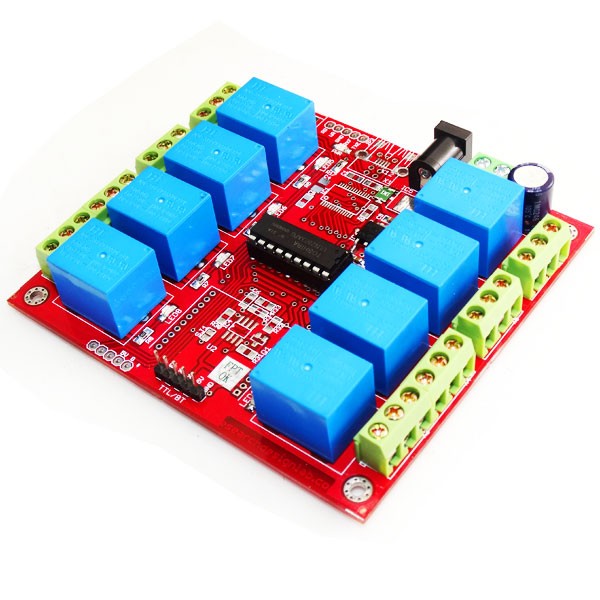
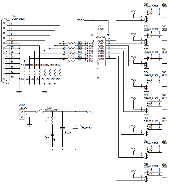
In our diagram we decided to set all the 8 pins from the A port as outputs, while the 8 pins from the B port were set as inputs. The outputs end on the U2 ULN2803 integrated circuit, a component that has been specifically projected as a driver for the relays (inside, it has different transistor stages available: they allow to drive the relays ... Jul 08, 2018 · 8 Channel 5v Relay Module Wiki. Wiring Bluetooth Hc06 In 8 Channel Relay With Android Arduino Microcontroller 14core Com. 8 Channel Relay Board Electronics Lab Com. 8 Channel Relay Board With Onboard 5v Regulator Electronics Lab Com. 8 Channel Relay Board Search Easyeda. 5v 8 Channel Relay Module Pinout Features Working Applications Datasheet. 8 channel relay board circuit diagram pdf. 3. Understanding Timer Delay Relay Function. Understanding all the time delay relay functions available in multifunctional timer can be an intimidating task. During the circuit design with the timer relay and variety of timer configuration, ... 8 Channel Relay Board is a simple and convenient way to interface 8 relays for switching application in your project. Input voltage level support TTL as well as CMOS. Easy interface with Micro controllers based projects and analog circuits. but in this bord is old . but PCB of new version of 8 channel relay module. with handle AC supply directly for home automation. this module are work same ...
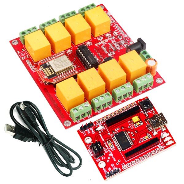
12 volt 8 channel relay wiring set up. Hi every body this is my 1st post on this site have just got myself an arduino uno and a duinotch 8 channel relay board rated at 12 volts i am new to this so i will listen to those that know. I have connected relay to arduiono uno board 5V pin to vcc pin on relay board. GND pin from Uno to GND pin next to ... This project is a general purpose 8 Channel Relay Board. Description 8 Channel Relay Board is a simple and convenient way to interface 8 relays for switching application in your project. Input voltage level support TTL as well as CMOS. Easy interface with Microcontrollers based projects and analog circuits. Specifications: Input supply 12 VDC @Read More Nov 03, 2021 · 13+ 8 Channel Relay Board Circuit Diagram. A relay can be used to control high voltages with a low voltage by connecting it to an mcu. This video is the clip of 8 channel relay circuit using transistor. Remotecontrolcircuit #remoteic #remotecontrolrelay remote control relay circuit friends, today in this video i am going to show. These relay modules are optoisolated, so you can protect your switching circuit from the circuit being switched by the relays. There are some important notes at the bottom of this post that you may want to read. It could solve your problem quckly. Heres what you need to do this project:-1 VUPN688 12V 8 channel relay module.-1 12V power supply
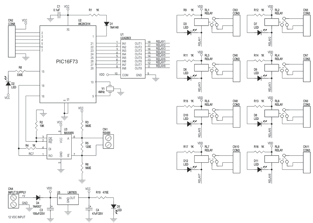
RLY-108 8-Channel TTL Relay Board Operating Instructions Auric Solutions Limited 14 Brent Court, Emsworth Hampshire PO10 7RJ, UK Tel. +44 (0) 7968 470945 info@auricsolutions.com ... Electrical circuit diagram for a single relay channel. RLY-108 8-Channel TTL Relay Board
So if youd like to receive all these awesome graphics related to 8 Channel Relay Board Circuit Diagram. Equipped with high-current relay AC250V 10A. A relay is commonly used to interface a low-current circuit to a higher-current circuit. We also discuss the. We collect this best photo from online and choose one of the best for you.

This is the complete circuit diagram for this home automation project. I have explained the circuit in the tutorial video. The circuit is very simple, I have used the GPIO pins D23, D22, D21, D19, D18, D5, D25 & D26 to control the 8 relays.. And the GPIO pins D13, D12, D14, D27, D33, D32, D15 & D4 connected with switches to control the 8 relays manually.
Jan 18, 2021 · 5V 8-Channel Relay Module. The eight-channel relay module contains eight 5V relays and the associated switching and isolating components, which makes interfacing with a microcontroller or sensor easy with minimum components and connections. Each relay on the board has the same circuit, and the input ground is common to all eight channels.
5V Relay Board 8 Channel Connections .. HELP ... Circuit Diagram. Voltage Divider. Measuring Instrument. Electronics Projects. Variables. Retro Fashion. Coding. Ps. DIY: Retro Style Analog Volt Meter using Servo Motor. Digital equipments have rapidly replaced Analog equipments in the long run. Well that is because the former has lot of ...


0 Response to "39 8 channel relay board circuit diagram"
Post a Comment