39 fuel oil tank installation diagram
Last video of how American Building & Environmental Services installs an outdoor 275 gallon #2 fuel oil storage tank. Part 3 of 3
The oil tank piping installation and testing standards cited below are the most-widely adopted throughout states and cities in the U.S. OIL STORAGE TANK CODES - full list of downloadable PDF copies of model and adopted building codes for oil tank installation & piping; 2014 New York City MECHANICAL CODE, CHAPTER 13 FUEL-OIL PIPING AND STORAGE [PDF]
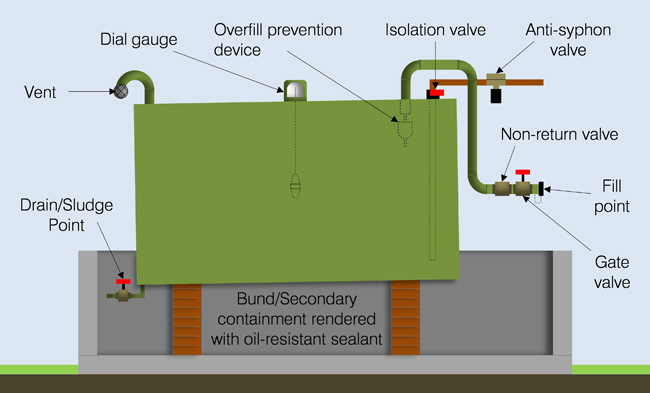
QUICK ENVIRONMENTAL. GUIDELINES FOR THE INSTALLATION OF ABOVE GROUND RESIDENTIAL OIL TANKS. The recommendations contained herein are considered standard industry practice for tanks constructed to NFPA 31, Standard for the Installation of Oil-Burning Equipment in the United States.Tank installations must also comply with the National Building and Fire Codes and any local codes that may apply.

Fuel oil tank installation diagram
q. 311. Local/remote low fuel level alarm, sensing 30% of capacity q. 312. Local/remote high fuel level alarm, sensing 103% of capacity q. 325. High fuel level emergency pump-stop switch q. 326. High level cutout for SDE Series only q. 329. Low fuel level red light q. 333. Critical low fuel level alarm-engine shut down q. 334. Alarm horn q. 340 ...
Oil Tanks and Piping Chapter 3 Chapter 3—Oil Tanks and Piping 3-3 Introduction The comfort, cleanliness and efficiency of today’s oilheat systems rely on clean, uncontaminated fuel reaching the oilburner. To achieve this: • Install tanks properly. • Maintain tanks by regularly inspecting them and fixing minor defects before
Fuel Tank Installation Guidelines for Installing Above Ground Oil Tanks July 24, 2018 by tyrussum 0 When installing Above Ground Oil Tanks, the recommendations within this guide are standard industry practices for tanks that were built to meet NFPA 31, Standard for the Installation of Oil-Burning Equipment in the US.
Fuel oil tank installation diagram.
The diagram below shows a Fuel oil supply system for a large 2 stroke crosshead engine. In the system shown in Figure, the oil from the service tank flows through a three-way valve to the supply pump. After that it goes to the mixing column through a filter and flow meter. A flow meter is fitted into the system to indicate fuel consumption.
Fuel Level Gauge 9 Outside Installation of a Single Tank 9 4 Roth Tank Installation Accessory Parts 10 Figure 3– Fuel Gauge Figure 4– Tie Down Kits 10 Figure 5– Roth Vent Alarm Figure Figure 6– Roth Tank Wrench 10 Figure 7– 2” NPT Die Cast Adapter Figure 8- Outdoor Tank Covers 10 Figure 9– Fuel Oil De-Aerator 11
The modern diesel fuel or fuel oil systems are used differently than systems designed a decade or more ago. In early fuel oil system designs, boilers were the primary user of the fuel. The fuel oil was a primary energy source used consistently throughout the year. With the advent of natural gas,
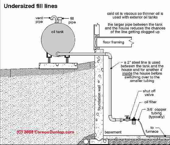
Place your tank at least five feet from any fuel-fed appliance and from any kind of heat source. You need to be able to walk around the tank and see all four sides of it clearly. 18 inches of clearance all the way around the tank should be sufficient but do verify this with your local building official. If the rules require you to provide more ...
Above ground oil tank requirements have been updated for ...
State of alaska

Is my oil tank safe? - garthwaite energy, inc.
Oil lines in concrete - why they need to be replaced - ed's ...
Buildings bulletins 2018-010 - technical
Fuel oil system with fuel oil cooler. | download scientific ...
Mechanical for oil heat - ppt video online download

Roth heating oil tank installation nh

Oil tank safety - vermont's new regulations and you | energy ...
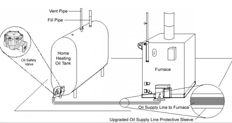
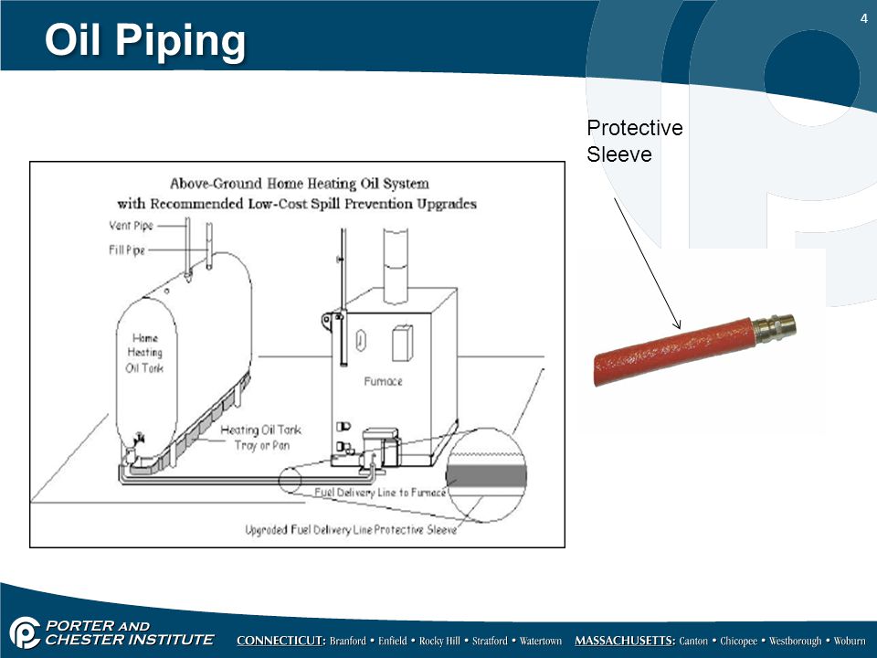
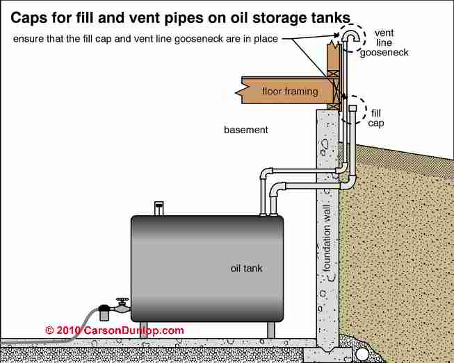
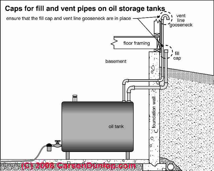
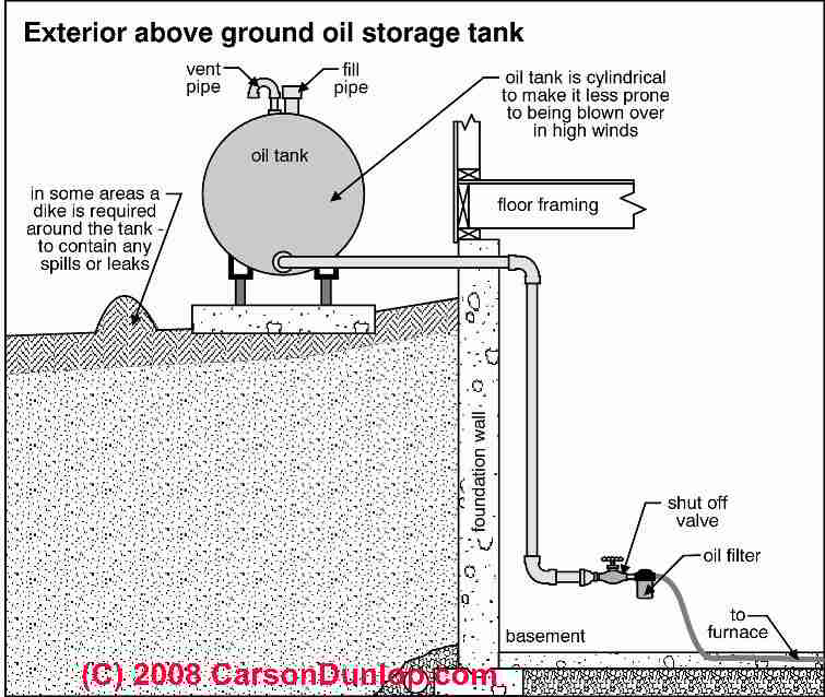
Oil tank fill & vent piping installation & inspection
Self help & faqs - husky heating oil
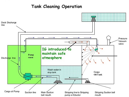
Standard procedures for tank cleaning, purging and gas free ...

Residential fuel oil tanks can vary... - ogee solutions inc ...

Single and double fuel tank piping diagram — heating help ...

Single and double fuel tank piping diagram — heating help ...

Oil tank maintenance and spill prevention - environment and ...
Heating oil tanks - lake washington building inspection ...
Is my oil tank safe?
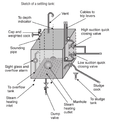
Heating of fuel oil storage tank - guideline for cargo ships
Oil piping for duplex or paired oil storage tanks
Heating oil piping defects & leaks: where heating oil leaks ...

Oil tanks & other tanks, inspection report language example ...

Investigating fuel oil leaks and spills – expert article ...
Fuel oil tanks | combined energy services

Car 1994 ford ranger wiring diagram fuel tank fuel pump ...
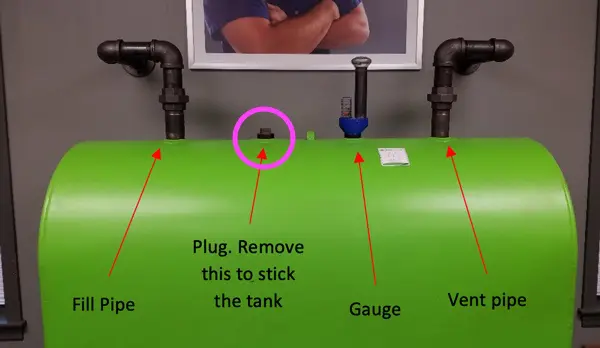
Get to know your oil storage tank

Fibreglass oil tank installation in barrie, ontario | c ...
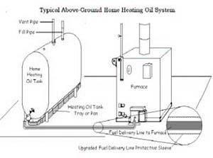
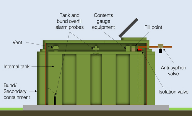
Above ground outdoor heating oil storage tanks (asts ...

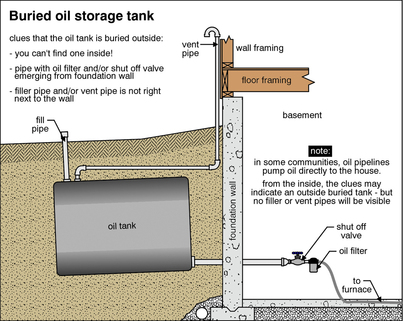
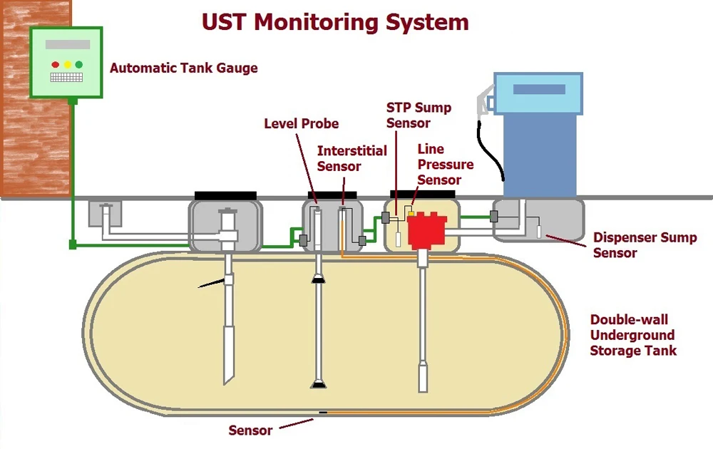
Typical underground fuel oil tank

Wiring diagram petroleum storage tank fuel oil, energy ...

Above ground stationary utility tanks - foremost fuel storage ...
Home heating oil tank installation guidelines

File:heating oil storage tank.png - wikimedia commons
Different volume optional crude oil storage tank fuel oil ...
Get to know your oil storage tank

Oil tank maintenance and spill prevention - environment and ...
Installing an oil tank? consider this - shipley energy
Installation and environmental management guide for ...
0 Response to "39 fuel oil tank installation diagram"
Post a Comment