41 converging lens ray diagram
A converging lens is one which the rays that enter it parallel to the axis converge toward the axis after exiting the lens. A diverging lens is one which these rays diverge away from the axis after exiting it. ... This calculator shows a ray diagram when the image is real. Magnification The magnification m of an image is the ratio between the ...
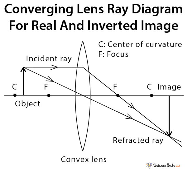
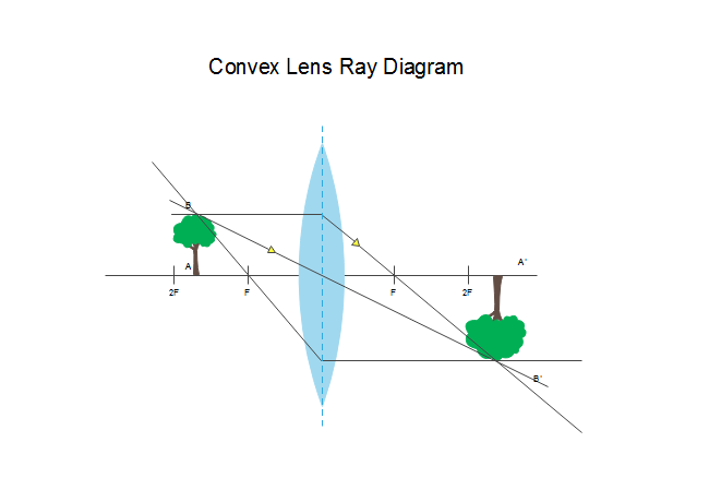
In order to illustrate the method of drawing a ray diagram for a converging lens, we will consider the situation in which a real object is placed to the left of a converging lens. The bottom of the object will sit on the optical axis, and the top of the object will sit above the optical axis.
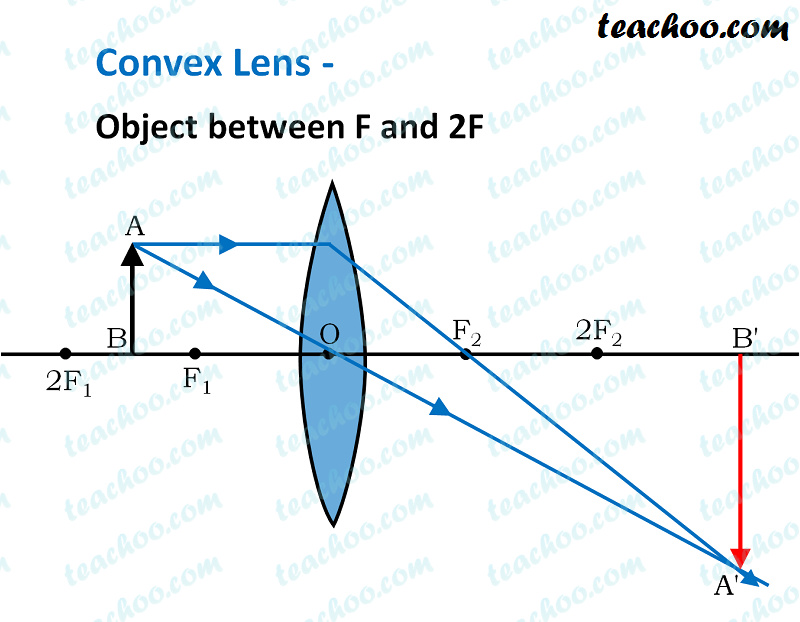
First, we draw a ray parallel to principal axis. So, it appears to pass through focus after reflection. We draw another ray which passes through Optical Center. So, the ray will go through without any deviation. Where both reflected rays meet is point A'. And the image formed is A'B'. This image is formed between F 1 and Optical Center (O)

Converging lens ray diagram
A convex lens is drawn as a vertical line with outward facing arrows to indicate the shape of the lens in a ray diagram, and the focal length is the distance between the lens and the principal focus. ... What are the three rules of refraction for converging lenses? An incident ray parallel to the axis refracts through the lens and passes ...
Converging and diverging lenses. ... In a ray diagram, a convex lens is drawn as a vertical line with outward facing arrows to indicate the shape of the lens.
A converging lens can be thought of as a set of blocks and prisms How does a converging lens converge light? ... Ray Diagram for Lenses How to locate the position of an image? 3 steps to locate the image: Step 1: Set up the lens and the ray diagram. Step 2: Placing the object.
Converging lens ray diagram.
12 draw a ray diagram for an object placed 60 cm from the surface of a converging lens with a focal length. When an object is very close to the concave mirror within focus a magnified and virtual image has obtained.
Converging Lens. Diverging Lens. F. Ray 1. F Ray 1. Ray 2. Ray 2. Ray 3 Ray 3. Images' ' Tracing Points Draw an arrow to represent the location of an object, then draw any two of the rays from the tip of the arrow. The image is where lines cross. Draw an arrow to represent the location of an
This physics tutorial shows you how to use the thin lens equation / formula to calculate variables such as the image height and image distance in addition to...
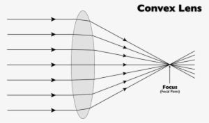
Converging Lenses A convex lens is a converging lens which bends light rays into focus. The focal length, f, is the distance to the focal point where parallel rays converge as shown. A Ray Diagram is a simple picture using only 2 or 3 light rays reflected off an object to visualize how images are formed.
The top diagram shows the formation of the virtual object where converging rays are prevented from meeting by the diverging lens. enter image. Any incident ray traveling parallel to the principal axis of a diverging lens will refract through the lens and travel in line with the focal point (i.e., in a direction such.Ray Diagrams for Lenses.
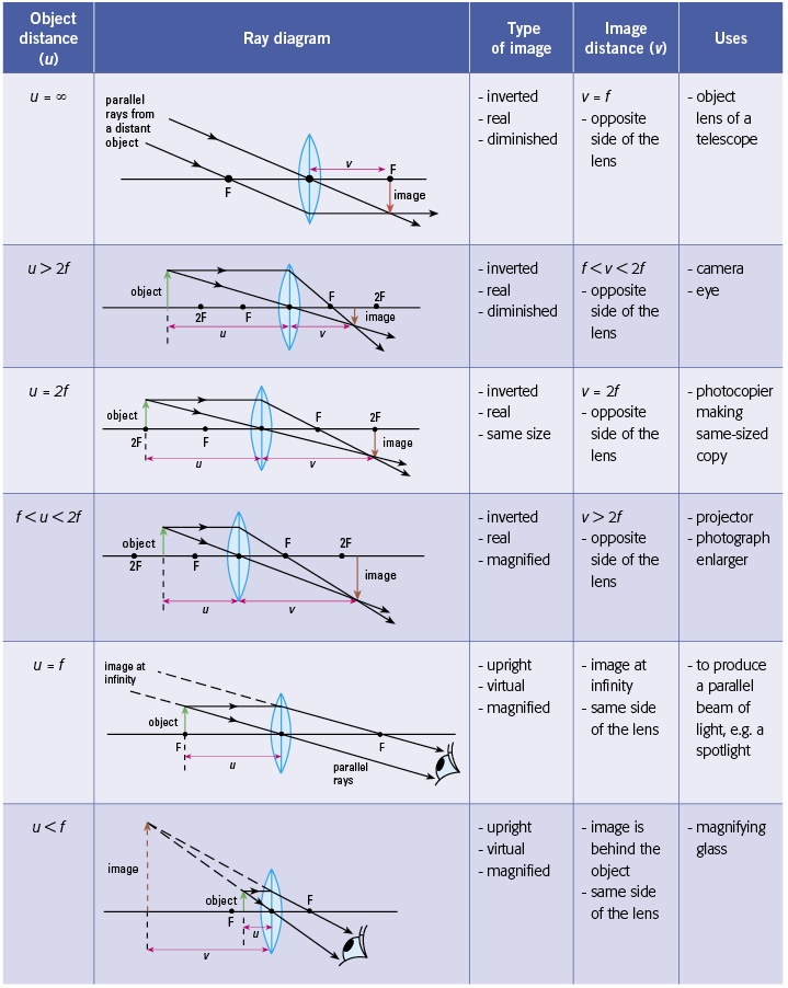
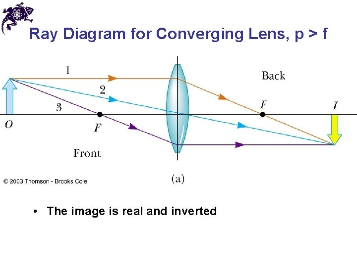
Draw and interpret simple ray diagrams that illustrate the formation of real and virtual images by a single converging lens. Based on where the object is placed, the image formed could be inverted/upright, real/virtual and reduced/enlarged. Inverted means that the image is upside down and upright obviously means that the image is the right way up.
Learn about and revise lenses and their power, real and virtual images, and ray diagrams with GCSE Bitesize Physics.
Diverging Lenses As such, the rules for how light behaves when going through a diverging lens is a little bit different. You will be expected to be able to draw a Ray Diagram of a converging and diverging lens on our upcoming test without the rules.
Parallel light rays that enter the lens converge · . They come together at a point called the principal focus ... In a ray diagram, a convex lens is drawn as a vertical line with outward facing arrows to indicate the shape of the lens. The distance from the lens to the principal focus is called ...
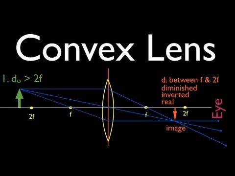
Ray tracing diagram for a converging lens, with the object beyond twice the focal length. (yes, the light actually bends at both surfaces, not the middle of ...
Convex Lens Ray Diagrams For lenses, the following three rays are typically used in ray diagrams. Keep in mind ... This ray, for a converging (convex) lens, then extends through the focal point on the opposite side of the lens. In Figure 4, the ray marked \1" is an example of this type of ray.
July 27, 2020 - The magnitude of the focal length is the distance from the lens to each focal point, while the sign tells us if the lens is converging or diverging. For a converging lens we take \(f > 0\), while for a diverging lens we take \(f < 0\). A typical diagram of a lens and its characteristics (i.e. ...
Ray diagrams for lenses
Sign in|Recent Site Activity|Report Abuse|Print Page|Powered By Google Sites
Ss: ray diagrams for converging lens - mini physics - learn physics
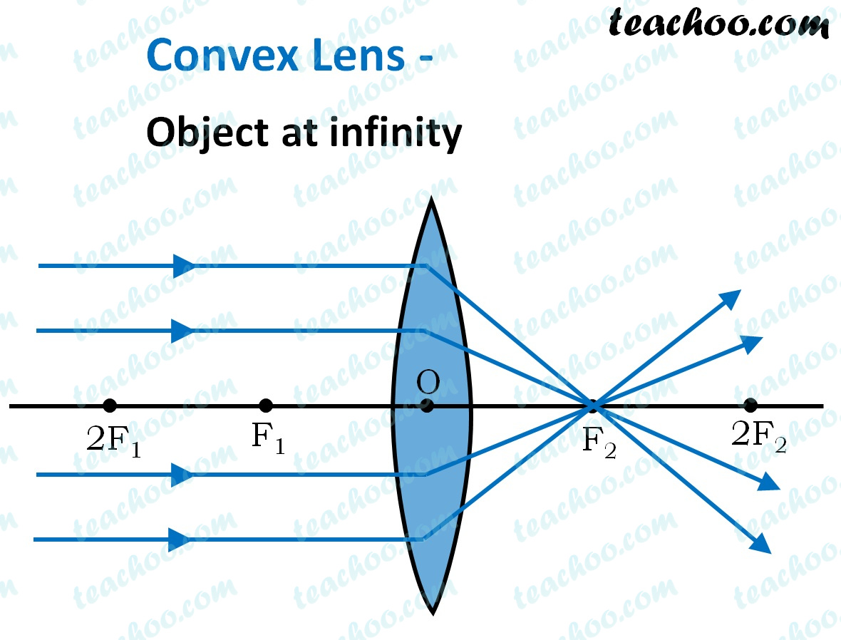
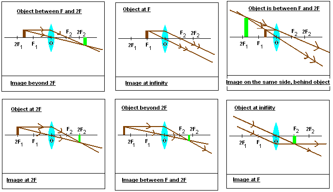
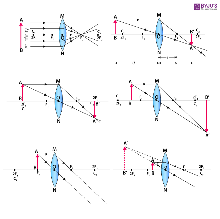
3 weeks ago - For a Convex Lens, object can be kept at different positionsHence, we take different casesCase 1 - Object is Placed at infinityIn this Case, Object is kept far away from lens (almost at infinite distance)So, we draw rays parallel to principal axisSince ray parallel to principal axis passes through t
Ray diagrams for lenses
This interactive tutorial utilizes ray traces to explore how images are formed by the three primary types of converging lenses, and the relationship between the object and the image formed by the lens as a function of distance between the object and the focal points. ... positioned more than twice the distance of the focal length away from a ...
Ray diagrams (2 of 4) convex lens
Here you have the ray diagrams used to find the image position for a converging lens. You can also illustrate the magnification of a lens and the difference between real and virtual images. Ray diagrams are constructed by taking the path of two distinct rays from a single point on the object.
Convex lens - ray diagram, image formation, table - teachoo
Get Physics Help Online from our Expert Physics Tutors. Avail a Free Physics Tutoring Session and get Help with Physics Concepts from the Physics Problem Solver.
Converging lens: definition, diagram, equation & application
April 11, 2020 - Convex lens forms real image because of positive focal length and concave lens forms virtual image because of negative focal length.

Drawing ray diagrams for a converging lens - the fizzics organization
The image formed by a single lens can be located and sized with three principal rays. Examples are given for converging and diverging lenses and for the cases where the object is inside and outside the principal focal length · The "three principal rays" which are used for visualizing the image ...
Physics tutorial: refraction and the ray model of light
Two Converging Lens Ray Diagram. Examples are given for converging and diverging lenses and for the cases where the The third ray is not really needed, since the first two locate the image. In this section of Lesson 5, we will investigate the method for drawing ray diagrams for objects placed at various locations in front of a double convex lens.

Pin on refraction and lenses
Convex lenses are also known as converging lenses since the rays converge after falling on the convex lens while the concave lenses are known as diverging lenses as the rays diverge after falling on the concave lens. In this article, we will learn about image formation by concave and convex lenses.

Image formation by convex and concave lens ray diagrams
December 25, 2015 - Trick to drawing ray diagrams for converging lens: There is one ray of light passing through the center of the lens. Always. 2 rays are enough to determine the position of image/object. The other r…

The open door web site : ib physics : optics : ray diagrams for ...
5) virtual, inverted, and diminished. Page 7. A real image is formed by a converging lens. If a weak ...15 pages

Lesson explainer: drawing ray diagrams for convex lenses | nagwa
Convex lenses are also known as converging lenses since the rays converge after falling on the convex lens while the concave lenses are known as diverging lenses as the rays diverge after falling on the concave lens. ... passing through focus strikes concave or convex lenses, the reflected ray will pass parallel to the principal axis. Image ...
Ray diagrams for lenses
Ray diagram for converging lens. Ray 1 is parallel to the axis and refracts as if from F. Ray 2 heads towards F’ before refracting parallel to the axis. Ray 3 passes straight through the center of the lens. image is always virtual, upright and reduced O F I F’ Ray diagram for diverging lens
Convex lens ray diagram | free convex lens ray diagram templates
Ray Diagrams By constructing a ray diagram, we can determine where the image is located, and what it will look like. A ray diagram is a diagram showing rays that can be drawn to determine the size and location of an image formed by a mirror or lens.
Ray diagrams for convex lens - online science home work
This Demonstration lets you visualize the ray diagrams for converging and diverging lenses. By manipulating the object and lens locations, you can create real or virtual images. The rays parallel to the principal axis and the ray through the center of the lens are drawn.Locators allow you to drag both the object and the lens. You can change the focal length using a slider. The degree of magnificat
Convex lens - ray diagram, image formation, table - teachoo
A converging lens is an optical lens that converges all rays of light passing through it. The primary purpose of a converging lens is to focus the incoming rays from an object and converge them to form an image. The image can be magnified, diminished, or remain the same depending on the distance of the object from the lens.
The photons of light then travels in all directions - simple ...
A ray diagram using this virtual object shows the location of the final image (bottom part of Figure O). Numerically, we can verify the accuracy of the ray diagram with: An arrow is placed 50 cm away from a converging lens (f= 25cm). On the other side of this first lens is a second converging lens (f. Ray Diagrams for Lenses. The image formed ...

The open door web site : ib physics : optics : ray diagrams for ...
Ray diagrams are constructed by taking the path of two distinct rays from a single point on the object. Here you have the ray diagrams used to find the image position for a converging lens. Ray Optics. Here you have the ray diagrams used to find the image position for a converging lens.
Ray tracing diagram for convex lens | physics diagrams | optics ...
The Physics Classroom » Curriculum Corner » Refraction and Lenses » Ray Diagrams for Converging Lenses. The document shown below can be downloaded and printed. Teachers are granted permission to use them freely with their students and to use it as part of their curriculum. Visit the Usage Policy page for additional information.

Lens ray diagram worksheet | pdf
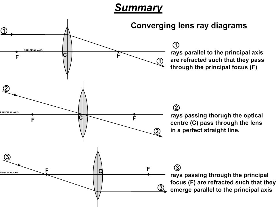
To explain how to draw the diagrams, there are two key things to remember. 1 A converging lens refracts the light so that any ray of light parallel to the principal axis (the thick horizontal line) is turned to pass through the focal point. Rays of light parallel to the principal axis are all refracted through the focal point.
Lenses - stickman physics
Here you have the ray diagrams used to find the image position for a converging lens. You can also illustrate the magnification of a lens and the difference between real and virtual images. Ray diagrams are constructed by taking the path of two distinct rays from a single point on the object. A light ray that enters the lens is an incident ray.

Nature of images by a convex and concave lenses - with ray ...
Ray Diagrams for Lenses. The image formed by a single lens can be located and sized with three principal rays. Examples are given for converging and diverging lenses and for the cases where the object is inside and outside the principal focal length. The "three principal rays" which are used for visualizing the image location and size are:

Ray diagrams for lenses royalty free vector image
Show/Hide Sub-topics (Converging Lens | O Level)Thin converging lensesRay diagrams for converging lensApplication of converging lens. There is one ray of light passing through the center of the lens. Always. 2 rays are enough to determine the position of image/object. The other ray of light ALWAYS passes through the focal point of the lens.

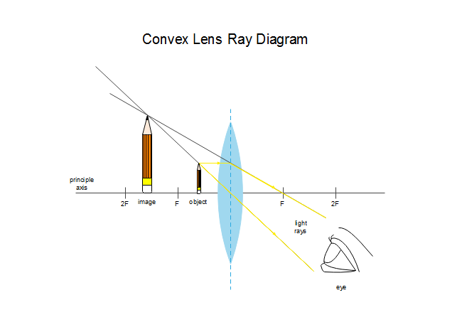
Human eye optics
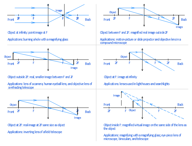
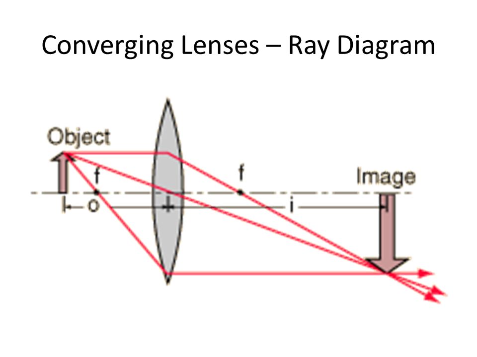
Ray Diagram for Object Located in Front of the Focal Point. In the three cases described above - the case of the object being located beyond 2F, the case of the object being located at 2F, and the case of the object being located between 2F and F - light rays are converging to a point after refracting through the lens. In such cases, a real image is formed.
Physics tutorial: refraction and the ray model of light

Lenses, ray diagrams for convex lenses

Physics - optics: lenses (2 of 5) lens combinations - two converging lenses

Open source physics @ singapore: ejss thin converging diverging ...

Sketch a ray diagram for a spherical convex lens with an object at ...
Gcse physics - ray diagram for an image made by a convex lens ...
One side convex lens ray diagram | free one side convex lens ray ...
Images formed by lenses ray diagrams for lenses ray diagrams can ...

1 principal ray diagram for a thin converging lens. in this ...

Lens ray diagram worksheet | pdf

20140227 converging diverging lens ray diagram worksheet
---teachoo.png)
Convex lens - ray diagram, image formation, table - teachoo
Chapter 31 images mirrors and lenses definitions images
Waves drawing ray diagrams for converging lenses. - ppt download
To find image distance for varying distance of a concave lens

Action of a thin converging lens | definition, examples, diagrams
0 Response to "41 converging lens ray diagram"
Post a Comment