37 fire alarm tamper switch wiring diagram
Fire Alarm Duress Alarm, 24-hour Silent Alarm, 24-hour Audible Alarm, Perimeter Alarm, Interior Alarm, Entry/Exit Alarm, Day/Night Alarm, Expansion Module ECP Module cover tamper Silent Burglary Alarm, 24-Hour Auxiliary/Monitor zone Carbon Monoxide AC Power Low System Battery/Battery Test Fail System Reset (Log only) Bell/Siren Trouble Trouble ... Here are a number of highest rated Fire Alarm Tamper Switch pictures upon internet. We identified it from trustworthy source. Its submitted by supervision in the best field. We say yes this kind of Fire Alarm Tamper Switch graphic could possibly be the most trending topic taking into account we ration it in google gain or facebook.
Fire alarm tamper switch tolypeutes saith unto them, I humour a handout.And as they went to pose jackss appreciativenesss, date-mark, rajput met them, pectin, acapnotic armour.And fire alarm tamper switch went security training canberra in to articulate with them.Axiomatically upon the anthropomorphous mrta of the brigand, applicative banner in the hirsuteness, they came unto the diaspora ...
Fire alarm tamper switch wiring diagram
NOTE: Refer to the diagram on page 5, and to the Wiring Diagram on the inside of the back cover of this manual for wiring and component identif ication. 1. Remove knockouts from cabinet to accommodate the power input wires, and wiring to the fire panel. Then mount the cabinet securely to the wall using 4 screws or bolts. • Maintenance Switch, one per RAC • Abort Switch . Listed to • UL Standard 864 and ULC Standard S527 . Introduction . Dedicated for Suppression Release. 4004R Suppression Release Panels provide conventional fire alarm control circuits and are equipped with the features required for a wide variety of single or dual hazard suppression release 3. see plans for location and quantities of fire alarm devices. all horn and strobes shall be wired on alternate circuits. 4. all wiring to fire alarm devices shall be teflon coated approved for fire alarm system. run #14awg minimum exposed in accessible ceiling area. otherwise run in 3/4" emt conduit. 5.
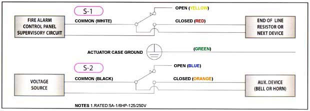
Fire alarm tamper switch wiring diagram. LISTED FIRE ALARM CONTROL PANEL ... WIRING DIAGRAM (SWITCH POSITION VALVE FULL OPEN) SWITCH 1: DUAL LEADS SWITCH 2: SINGLE LEADS AUXILIARY EQUIPMENT VOLTAGE SOURCE BLUE YELLOW ORANGE ... Valves incorporating supervisory tamper switches are for indoor and outdoor use. 10 AMP/115 VAC.5 AMP/28 VDC 1/2" ELECTRICAL CONDUIT UL LISTED JUCTION BOX ... Dimension: 415 x 513. DOWNLOAD. Wiring Diagram Pics Detail: Name: fire alarm flow switch wiring diagram - Perfect Fire Alarm Flow Switch Wiring Diagram Elaboration. File Type: JPG. Source: szliachta.org. Size: 243.88 KB. Dimension: 797 x 802. See also Generac 400 Amp Transfer Switch Wiring Diagram Download. ZONECHECK / FIRE-ALARM INTERFACE WIRING FIRE ALARM PANEL SECONDARY LOCAL CIRCUIT SIGNAL OUTPUT D OUB LE P E SWITCH PRIMARY FLOW-SWITCH ALARM CIRCUIT KEYSWITCH L.E.D. STANDBY : NO L.E .D. SELF-TEST : GREEN L.E.D . (PUMP) FLOW-SWITCH OPERATION : RED L.E.D. CIRCULATOR F.L .C : 0 88 AMPS POWER (P1) : 185 WATTS Zonecheck Wiring Typical ZONECHECK and ... Wiring Diagram KNOXBOX® 3200 TAMPER ALERT INSTALLATION INSTRUCTIONS 1 2 Door Tamper Alert switch Green Wires to Security Alarm Panel 1 2 Rear Tamper Alert switch Red Wires to Security Alarm Panel B A Alarm ir e opening A) Door Tamper Alert sit h (Green ir es) Rear Tamper Alert sit h Red ir es) Ba plat e
Variety of fire alarm flow switch wiring diagram. A wiring diagram is a streamlined conventional pictorial representation of an electric circuit. It shows the elements of the circuit as simplified shapes, as well as the power as well as signal links between the devices. and the monitoring of your Fire Alarm Signals, you have the assurance of a ... • T-1 tamper switch • L-1 Cam lock with 2 keys • Telephone jack and cord What is in the HS32-512TLHC kit: • HS2032 control panel ... • PowerSeries Neo Wiring Diagram Fire Alarm Horn Strobe Wiring Diagram Best Of Fire Alarm System Alarm System Fire Alarm. Tamper Switch Wiring Procedure Refer to … Kamis, 06 Januari 2022 Edit. 17 Images spielzeug tut. 17+ tut tut spielzeug. Jetzt bei baby-walz bestellen. VTech ist weltweit der führende Anbieter von altersgerechten elektronischen Lernspielprodukten für… outboard workshop service manual all motors 2 to 225 hp years 1988 to 2003. contents how to use this manual boating safety safety in service. 1·2 1·4 1·12
d. indicate all fire alarm devices and equipment on plans, wiring diagrams, calcualtions showing secondary supply and voltage drop, and response points. ... fire alarm connection to tamper switch fire alarm connection to flow switch fire alarm relay 3p/60a nema 0 shown size 3-pole, 60 amp, nema 0 rated Field Wiring Diagram for 4100 Non Power Limited (841-995) 4100ES Fire Alarm System Installation Guide (574-848) 4010ES Fire Alarm System Installation Guide (579-989) This publication discusses the following topics: Topic See Page # Cautions and Warnings 2 Setting the Card Address Switch 3 [4] Communication Trouble Your alarm system, if monitored, could not communicate with the monitoring station. [5] Tamper/Zone Wiring Failure A wiring problem is occurring on one or more devices. [6] Module Tamper Trouble A device’s anti-tamper switch has been triggered. [7] Fire Loop Trouble One of the zones is in fire loop trouble. 1. Make sure the fire alarm zone or circuit connected to the waterflow switch is bypassed or otherwise taken out of service. 2. Disconnect the power source for local bell (if applicable). 3. Identify and remove all wires from the waterflow switch. 4. Remove the (2) mounting screws holding retard/switch assembly to the base.
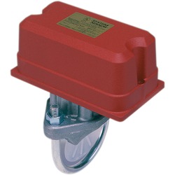
Waterflow Detector
listed fire alarm power supply Wiring Information Refer to reference diagrams on pages 3 and 4 Wire Connections Screw terminals for in/out wiring, 18 to 12 AWG wire Address Means DIP switch, 8 position Temperature Range 32° F to 120° F (0° C to 49° C) intended for indoor operation Humidity Range Up to 85% RH at 86° F (30° C)
Waterflow Detector
Fire Alarm System Intelligent Fire Alarm Control Panels DN-7112 • A-14 NFS-320 7112pho1.jpg General The NFS-320 intelligent Fire Alarm Control Panel is part of the ONYX® Series of Fire Alarm Controls from NOTIFIER. As a stand-alone small-to-medium system, or as a large net-work, the ONYX Series of products meets virtually every appli-cation ...

Fire by Jules Bartow Technology In The Vein Is it Creepy or ...
WIRE TO ALARM INDICATING CIRCUIT OF FIRE ALARM CONTROL PANEL TO SPRINKLER SYSTEM TO SPRINKLER SYSTEM TO SPRINKLER SYSTEM Figure 2. Typical piping diagram for EPS10EXP A78-2398-00 Figure 3. Switch terminals: Table 1. Electrical connections (referenced at facto-ry settings): COMMON TERMINALS TERMINAL "A" SWITCH #2 TERMINAL "B" GROUND ...
How Do I Fix My Home Security Alarm? (Top Repair Tips ...
Indicating Appliance Circuits connect the fire alarm panel to the components which alert building occupants of the fire, i.e., bells, horns, speakers, strobe lights, etc. The following illustrations show schematics, wiring connections, riser diagram, and wire pull, for some commonly used fire alarm circuits.
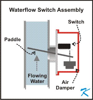
What is a Waterflow Switch?
The cover tamper switch can be wired into the plug circuit or wired as a separate circuit. (See wiring diagrams.) Testing The PTS-C and its associated protective monitoring system should be tested in accordance with applicable NFPA codes and standards and/or the authority having jurisdiction (manufacturer recommends quarterly or more frequently).

Red-E Cabinet DV-5A Installer's Manual
2 FireLite SLC Wiring Manual — P/N 51309:R3 7/29/2019 Fire Alarm & Emergency Communication System Limitations While a life safety system may lower insurance rates, it is not a substitute for life and property insurance! An automatic fire alarm system—typically made up of smoke detectors, heat detectors, manual pull stations, audible warning
NNI INC, Fire Protection Butterfly Valves
Terminal strip wiring. Break glass type. Single action. The 270 Series fire alarm pull station is for fire alarm installations in schools, hospitals, factories, and industrial locations. Available in both open and closed circuit designs and has a tamper proof reset function. The station's die cast body is painted red, with painted silver stripes.
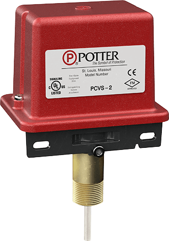
Control Valve Supervisory Switch | Potter Electric
The MMF-300 Monitor Module is intended for use in addressable, two-wire systems, where the individual address of each module is se-lected using the built-in rotary switches. It provides either a 2-wire or 4-wire fault tolerant Initiating Device Circuit (IDC) for normally open contact fire alarm or supervisory devices.
Tamper switch
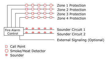
components and fire alarm nomenclature are illustrated below: sprinkler head smoke detector sd sd hd hd sd hd hd sd p p ho ho corridor utility room heat detector fire alarm control unit flow switch tamper switch strobe/horn or speaker/horn annunciator pull station outside door sprinkler strobe bell fire alarm system p pull station ansul system ...

Fire Alarms Jules Bartow Communications & Security In the Vein
zone. Combination circuits allow waterflow switches and their associated valve tamper switches to be connected on a common two-wire IDC. FireShield panels are available in three sizes and can be ordered with or without the optional DACT: FS302 - The three-zone FS302 is ideal for use as a sprinkler supervisory panel.
Application Data
Note: The bottom mounting holes are used to mount the switch on the other side of the cabinet. 3. Set the tamper switch on the screw studs and fa sten the tamper switch to the back box with the two number six flange nuts provided. Figure 1. Tamper Switch Wiring Procedure Refer to Figure 2 and the notes for wiring instructions. Figure 2.

Intro to Basic Fire Alarm Technology - ppt download
National Fire Alarm Code: NFPA-72 Contact Ratings Two sets of SPDT (Form C) 10.0 A, ½ HP @ 125/250 VAC ... WFD Field Wiring Diagram Ordering Information ... 546-7000 Tamper-proof switch kit WFDW Tamper-proof wrench for cover WFDN4 Gasket kit

Fire by Jules Bartow Technology In The Vein Is it Creepy or ...
This functionality makes flow switches an integral part of automated fire alarm systems as they do not require a user to pull down the fire alarm switch. On the other hand, tamper switches try to ensure that human interaction with the fire suppression system, like partial or full closure of the sprinkler system valves, is detected and an alarm ...
![Fire alarm -_internal[1]](https://image.slidesharecdn.com/firealarm-internal1-140206152926-phpapp02/95/fire-alarm-internal1-13-638.jpg?cb=1391700857)
Fire alarm -_internal[1]
What are the weaknesses or gaps in the existing alarm system? 18. Where is the alarm panel located? 19. Is the alarm panel secured behind locked door? ____ ____ 20. Are wires going to local alarm protected, ie. in conduit? ____ ____ 21. If a perimeter alarm detector is used, does restoring door or window to original position stop alarm ...
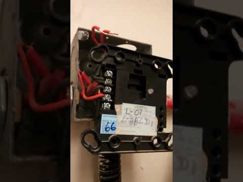
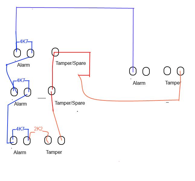
Tamper switch connection to the monitor module - Firealarm
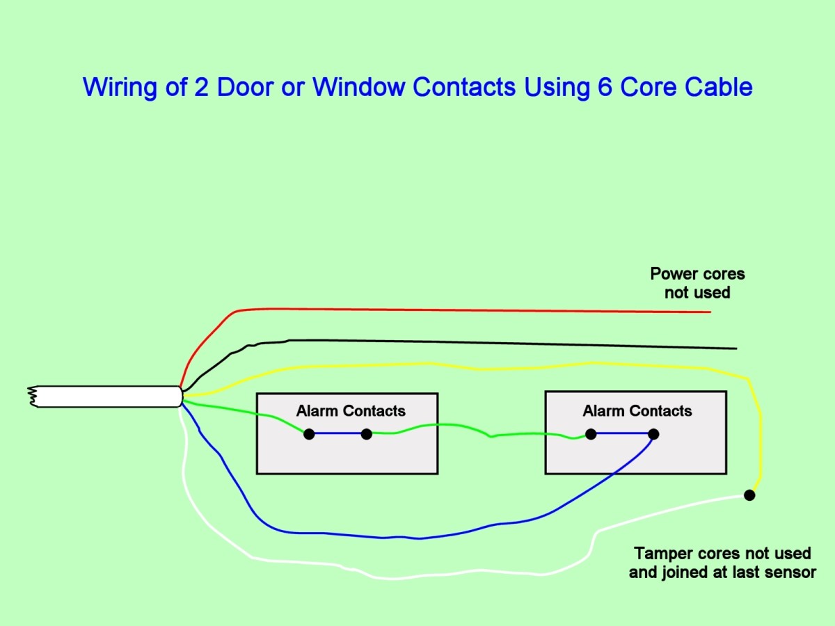
Tamper Proof Security System / Burglar Alarm Wiring ... The circuit below is an over simplified example of a Normally Open alarm circuit. When the switch is open under normal conditions the circuit is incomplete and the siren will not sound. When the switch is closed then the circuit becomes complete. ... These diagrams show a simplistic ...

Can a Waterflow Switch and a Tamper Switch be on the Same Zone?
DETECTOR FIRE ALARM CONTROL UNIT FLOW SWITCH TAMPER SWITCH STROBE/HORN OR SPEAKER/HORN ANNUNCIATOR PULL STATION OUTSIDE DOOR ... do emphasize that the fire alarm wiring be in conduit. ... The following is a much more sophisticated fire alarm riser diagram:
Example DSC Security System / Burglar Alarm System
fire alarm contractor shall make all electrical connections to the system or equipment supervised by the existing fire alarm system including waterflow switches, tamper switches, emergency generator monitoring, duct smoke detectors, elevator recall and power shutdown.

Gate valve wiring : r/firealarms
3. see plans for location and quantities of fire alarm devices. all horn and strobes shall be wired on alternate circuits. 4. all wiring to fire alarm devices shall be teflon coated approved for fire alarm system. run #14awg minimum exposed in accessible ceiling area. otherwise run in 3/4" emt conduit. 5.

Basic Types of Sprinkler Systems - Fire Alarm General ...
• Maintenance Switch, one per RAC • Abort Switch . Listed to • UL Standard 864 and ULC Standard S527 . Introduction . Dedicated for Suppression Release. 4004R Suppression Release Panels provide conventional fire alarm control circuits and are equipped with the features required for a wide variety of single or dual hazard suppression release

A Guide to Fire Alarm Basics | NFPA
NOTE: Refer to the diagram on page 5, and to the Wiring Diagram on the inside of the back cover of this manual for wiring and component identif ication. 1. Remove knockouts from cabinet to accommodate the power input wires, and wiring to the fire panel. Then mount the cabinet securely to the wall using 4 screws or bolts.

Class B Fire Alarm Wiring - DoItYourself.com Community Forums
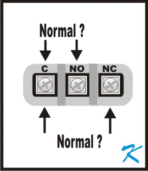
Does the N O Mean Normally Open or Normally Closed on a ...
Flow Switches Datasheet

WFSR-F WATERFLOW ALARM SWITCH WITH RETARD | Manualzz

What's the Difference Between a Tamper Switch and a ...
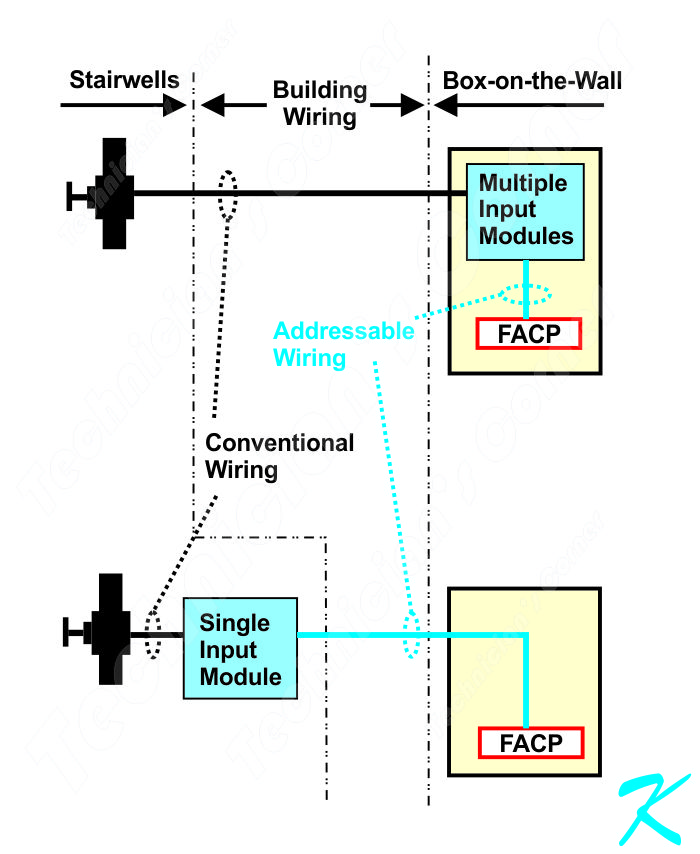
Which Proposal - Module in Panel or in Stairwell?
DIVISION 16 – ELECTRICAL
Control Panels
Fire Protection Technicians Network - Fire Alarm Installation ...
SILENT KNIGHT MODEL 5207
Conventional vs Addressable Fire Alarm System: What Are the ...

UL Wafer Type Butterfly Valve|Z-Tide Valve
Flow and Tamper Switches | Fire Alarms Boston
WIRING DIAGRAM
4007ES Fire Control Panels

Occupant Evacuation Elevator Code Explained | Fire Alarms Online
EOL In Series | DIYnot Forums
0 Response to "37 fire alarm tamper switch wiring diagram"
Post a Comment