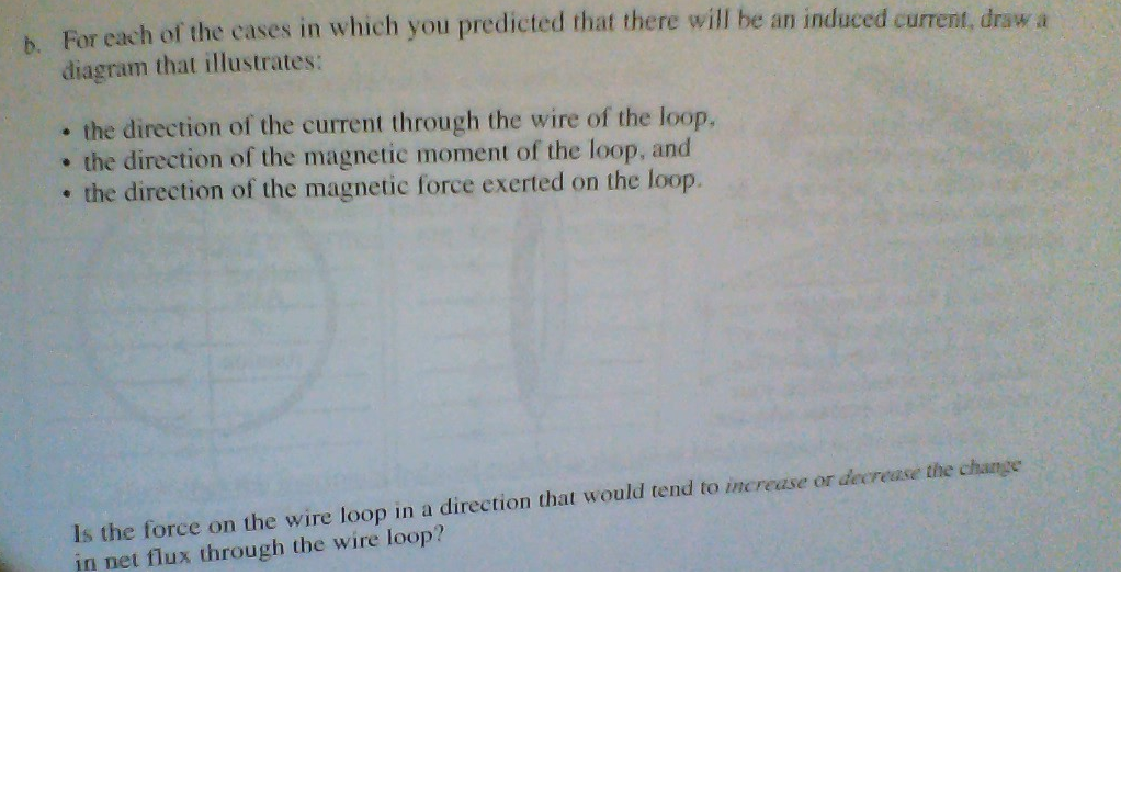
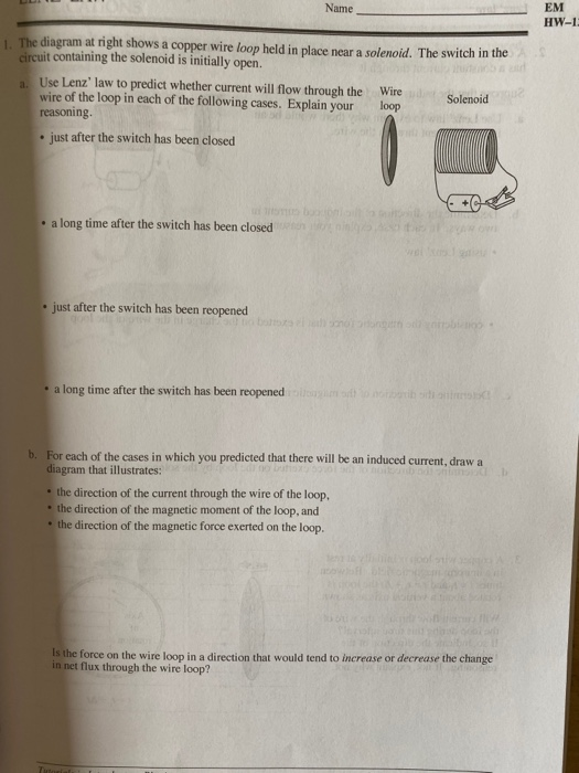
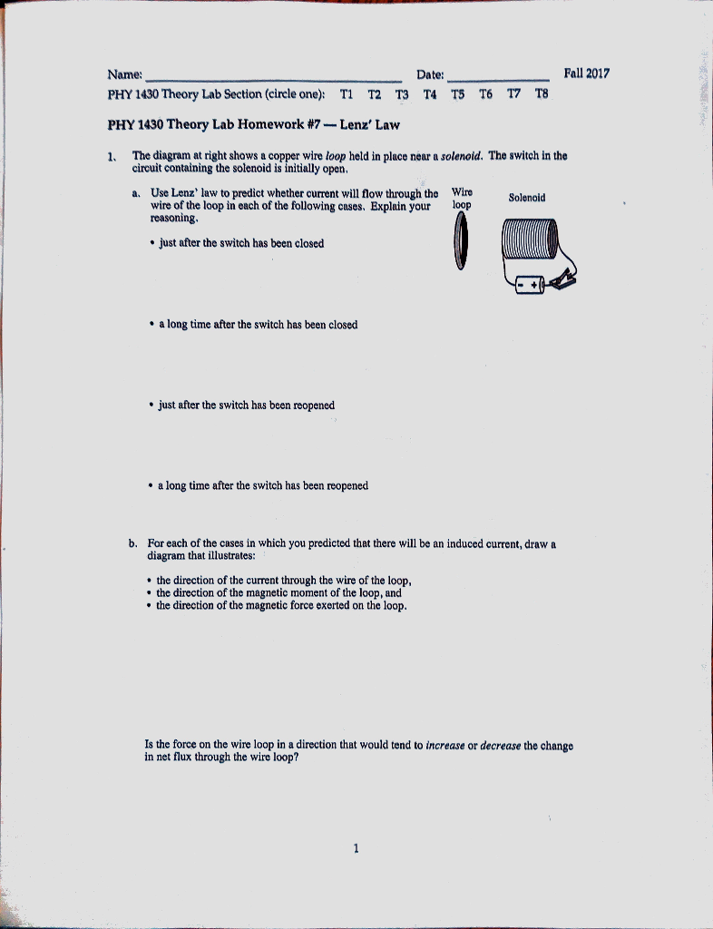
41 the diagram at right shows a copper wire loop held in place
Aug 10, 2020 · The thumb, the fore finger, and the center finger of the right hand must be held at the right angles to one another. The forefinger shows the direction of the magnetic field, the thumb shows the direction of motion of conductor, and the center finger shows the direction of the induced current in the conductor. Q20. This device is marked as suitable for copper wire only. At above right is a top view of a #12 copper wire inserted into one of the clamp type electrical receptacle openings. At right in the same photo you can see the silver edge of the clamp pushed against the copper plate beneath the screw when the device is fully closed.
3. Place the fully opened lensatic compass on the map with the scale edge running through the terrain feature and with the compass reading the same as the azimuth sighted. Draw a line along the scale edge. 4. Pick another visible terrain feature and sight its azimuth. For greater accuracy the two lines should be approximately right angles. 5.

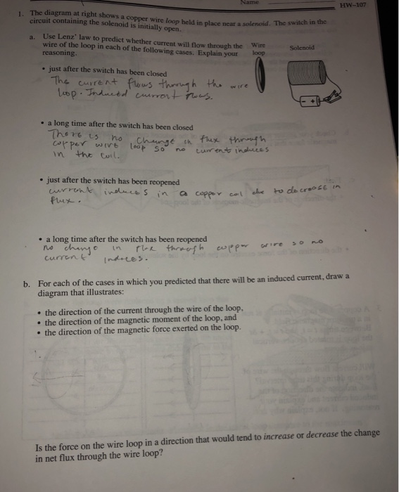
The diagram at right shows a copper wire loop held in place
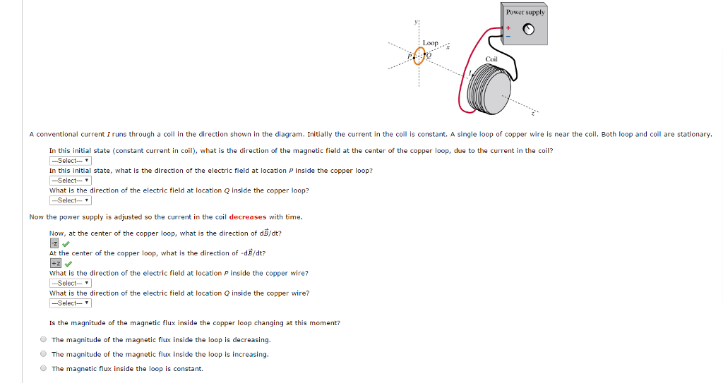
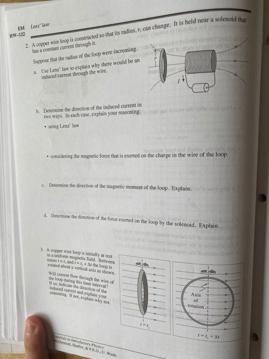
The following diagram shows the broad side array, in front view and side view, respectively. The broad side array is strongly directional at right angles to the plane of the array. However, the radiation in the plane will be very less because of the cancellation in the direction joining the center. Problem 1 (13 points) The diagram shows a copper wire loop held in place near ... This results in an increasing magnetic field pointing to the right of the ... The diagram a1 right shows copper wirc loop held in place ncar & solcnoid. The switch in the cinuit containing the solenoid initially open.4 answers · Top answer: Hi. I'm the given problem here. This is a circuit having a resistance, Marcel And a switch ...
The diagram at right shows a copper wire loop held in place. Tne diagram at right shows copper wire loop beld in place near solenoid, The switch in ... And this conductor has been kept who actually to a long solenoid.5 answers · 6 votes: A copper wire of insignificant resistance is placed in the center of an air gap between two ... Identical copper wire loops are placed in different external magnetic fields, ... A. The diagram at right shows a stationary copper wire loop in a uniform.8 pages Problem: The diagram at right shows a copper wire loop held in place near a solenoid. The switch is the circuit containing the solenoid is initially open.a.1 answer · Top answer: Lenz's law of electromagnetism states that an induced electric current flows in a direction such that the current opposes the change that induced it. ... Question: I. The diagram at right shows a copper wire loop held in place near a solenoid. The switch in the circuit containing the solenoid is initially ...
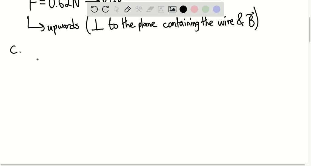
The diagram shows electricity flowing from left to right through a wire. Follwing the left hand-rule the wire experiences a force pushing it upwards and a magnetic field that moves from north (in the bottom-left) to south (at the top-right). Figure 3. The diagram at right shows a copper wke loop held in place near a solenoid' The switch in the circuit con'.aining the solenoid is initially open. Wire loop. The diagram at upupexact shows a copper wire loop held in assign adjacent a solenoid. The switch in the tour containing the solenoid is initially disclosed. 1· ... In the photo above you can see that the open end of the hooked copper wire pushes against a factory-designed raised lug or protrusion on the side of the receptacle. This feature gives a pushing surface against which the hooked wire can be pushed to close the loop. Option: close the wire loop around the binding head screw shaft.
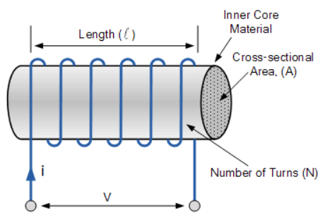
Jan 01, 2022 · Even in current carrying loop, the right hand thumb rule is obeyed. This shows that the magnetic field lines are present around the conducting wire. But the circular shape of conductor means that field lines at different points of the loop appear to be making ring around the periphery of the loop. This looks like small ring looping around big ring. The diagram a1 right shows copper wirc loop held in place ncar & solcnoid. The switch in the cinuit containing the solenoid initially open.4 answers · Top answer: Hi. I'm the given problem here. This is a circuit having a resistance, Marcel And a switch ... Problem 1 (13 points) The diagram shows a copper wire loop held in place near ... This results in an increasing magnetic field pointing to the right of the ... The following diagram shows the broad side array, in front view and side view, respectively. The broad side array is strongly directional at right angles to the plane of the array. However, the radiation in the plane will be very less because of the cancellation in the direction joining the center.
Wireless Pond Temperature
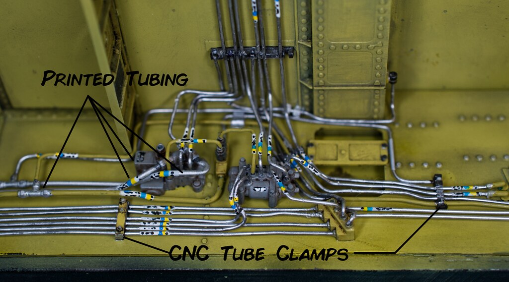
Sepecat Jaguar GR3.A / GR1.A in 1/12th Scale - Works in ...
new white prepac large cubbie bench 4820 storage usd $ 114 ...

PALASM_2_Software_Jul87 PALASM 2 Software Jul87
Majestic Mighty Monarch of the Air
DA's Europa

PHYSICS TUTORIAL - ELECTROMAGNETICS SORRY IF THE | Chegg.com

L'arc de Triomphe
Solved: PHYSICS TUTORIAL - ELECTROMAGNETICS SORRY IF THE I ...

Solved: The Diagram At Right Shows A Copper Wire Loop Held ...

PLEASE READ! I have had two people now approach me saying ...
40 the diagram at right shows a copper wire loop - Wiring ...

40 the diagram at right shows a copper wire loop - Wiring ...

Scale Model Bench: Arado Ar 234 "Blitz" (Hobbycraft 1:48 ...

This is a long exposure of the Milky Way, captured at Copper Mountain in Colorado.

Shay Boiler

Michael Heath-Caldwell M.Arch - 1948 Journal for the Use ...
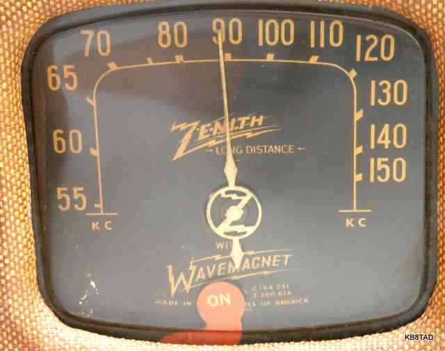
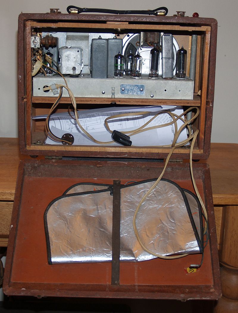
Zenith 5G500 and 6G501M Universal 3-way portables

Modern Vespa : LX150 Turn signal Euro Mod + buzzers.

Michael Heath-Caldwell M.Arch - 1948 Journal for the Use ...
.jpg)
Tamiya Dragon Wagon - Work in Progress - Armour ...

Make Beaded Candy Cane Christmas Ornaments : 7 Steps ...
TI-99 Console
40 the diagram at right shows a copper wire loop - Wiring ...
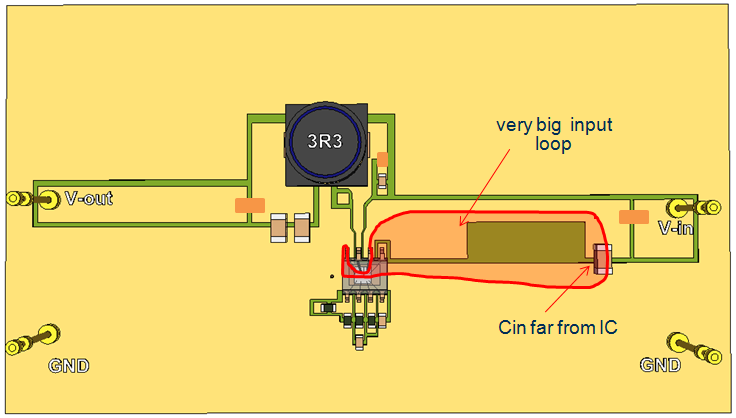
Reducing EMI in buck converters | Richtek Technology
Solved: Name EM HW-1: The Diagram At Night Shows A Copper ...
Solved: The Diagram At Right Shows A Copper Wire Loop Held ...

PHYSICS TUTORIAL - ELECTROMAGNETICS SORRY IF THE | Chegg.com

Obsolete Technology Tellye !: GRUNDIG TRIUMPH 1216 CHASSIS ...
The JH String Filter
Sailplane #83
RM-1 Supersonic Fighter | Model Aviation
Solved: HW-107 1. The Diagram At Right Shows A Copper Wire ...
40 the diagram at right shows a copper wire loop - Wiring ...
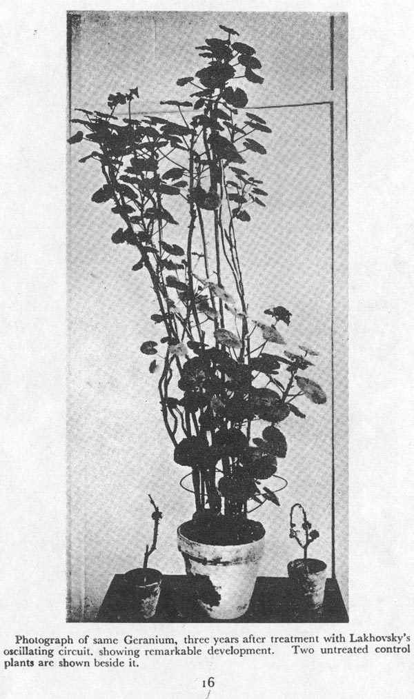
MWO-Lakhovsky's MultiWave Oscillator
Solved: Name EM HW-1: The Diagram At Night Shows A Copper ...

Fishmarket

Used Andreja Premium with loose green wire? - Page 2
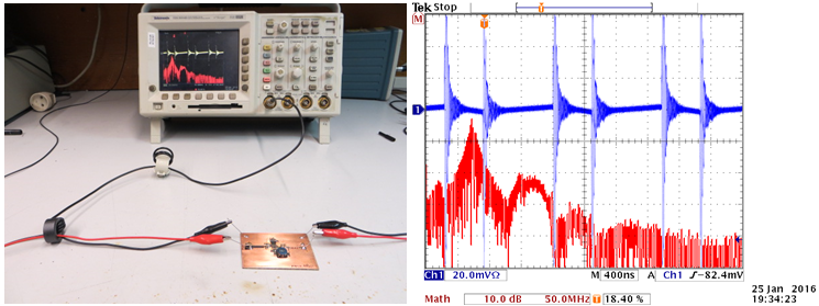
Reducing EMI in buck converters | Richtek Technology

The JH String Filter
40 the diagram at right shows a copper wire loop - Wiring ...
0 Response to "41 the diagram at right shows a copper wire loop held in place"
Post a Comment