37 arcade button wiring diagram
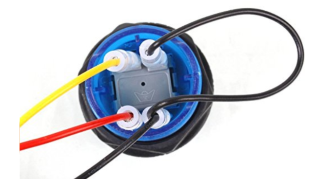
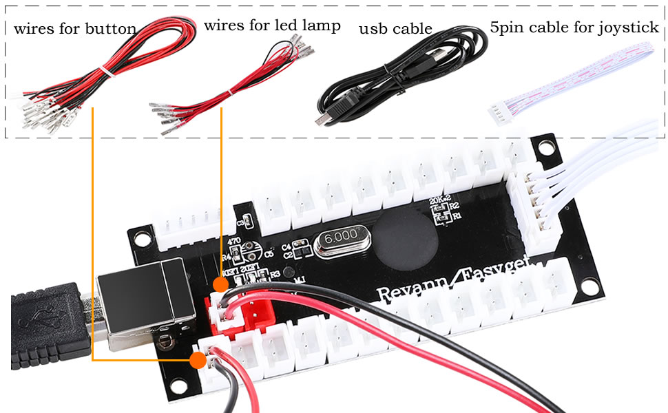
Build a daisy chained wire harness to connect to the +5v connector on your existing board. This will power the led portion of the buttons (which by the way are the other two pins on the image you included). You will need to determine which pin on the connector is power and which ground. Repeat this process for each potentiometer leg and arcade button leg, referring to the wiring diagram. Not every joint will be the same, so make sure you know what wire needs to go where. Don't solder anything to the bottom right most arcade button (on pin 13) as it's quite different and covered in the next section.
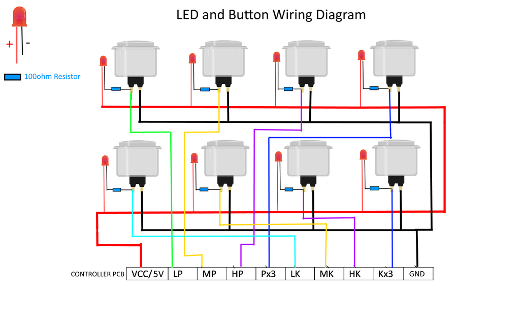
Circuit Diagram This provides a visual reference for wiring of the components. They aren't true to scale, just meant to be used as reference. The LEDs are embedded into the arcade button housing. They appear separate in the diagram for clarity. To power this project, we're connecting microUSB to a computer's USB port.

Arcade button wiring diagram
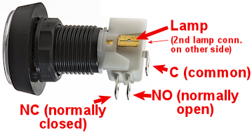
Jul 03, 2009 · The most common wiring setup for a microswitch is to have the ground wire on the very bottom prong (the common prong) and the action wire on the prong closest to the ground wire (the normally open prong). This will send a signal to the board whenever the button is pressed. This setup is used in the majority of arcade games that you will encounter. Diagram of how the buttons and switches are wired to the I-Pac for the ArcadeCab Control Panel Layout It is usually easiest for you to install all the joysticks and buttons in the control panel first. Then go around and add the cherry switch to each button. The joysticks should have come with problem is, i cannot find a wiring diagram anywhere, and it has gotten to the point that i post a question in the forums. i would like to just use the four buttons i have installed, along with the player 1 and 2 buttons, but if i have to cut a new piece of wood, that is nothing. thanx and have a great night.
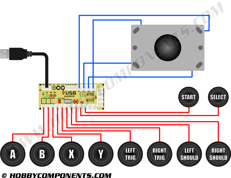
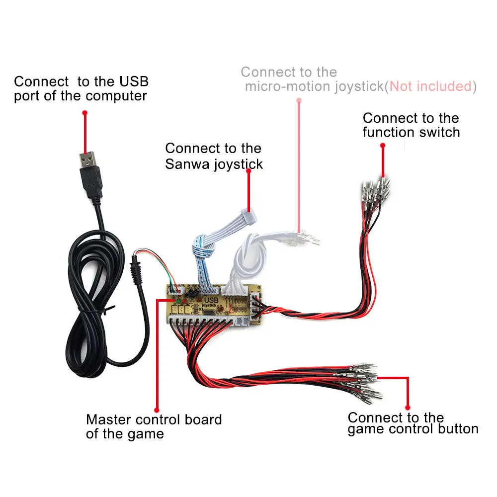
Arcade button wiring diagram. Plug one end of the ribbon cable into the joystick port, then plug the other end onto the 5 pins on the joystick. Make sure to get the orientation correct, which is white side of the ribbon facing up, towards the red ball on the joystick Once we've got that sorted, we can start to plug in the button wires. Lets start with the pre-defined buttons. JAMMA Wiring Harness Multicade 60 in 1 Arcade Game Cabinet Wire Labels Free Hot. $ Free diagramweb.net Rating: % positive. New Full Jamma Plus+ Harness Features: > Now includeds button 5 and 6 for both player 1 and 2 > Includes button 5 and 6 quick connector for Jamma boards with external button hookup such as the in-1 PCB. Great solution to connect both buttons, joysticks and led strips when using led lighting and you don't want to mess around with a arcade power supply and use a ac adapter instead. 5 Wiring For Illuminated Buttons Project MAME - Basic Arcade and MAME joystick and push button wiring guide ... Panel Layout Retropie Arcade, Arcade Bartop, Arcade Joystick, Mini Arcade.
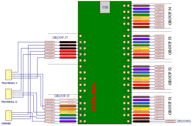
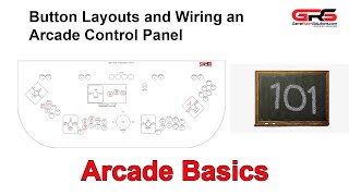
In this video we will walk through the different button layouts and a wiring basics overview for your arcade machine. There are several different layouts th... Harness: Ready made wiring or what you call your finished wiring Micro switch: Commonly used switch used for joystick and push buttons. Sometimes you will encounter micro switches with three legs instead of two. The illustration shows where you need to connect your wiring. Black = All black wires are ground (use a ground with each wire below) White = Mouse Button 1 (mouse 0 in MAME) - On X-Arcade = Left Pinball button Brown = Mouse Button 2 (mouse button 1 in MAME) - On X-Arcade = Right Pinball button Orange = Mouse Button 3 (mouse button 2 in MAME) - On X-Arcade = Red-lit Exit button The diagram below provides a visual reference for wiring of the components. This diagram was created using the software package Fritzing. ... Arcade Button with LED - 30mm Translucent Clear. $2.50. Add to Cart. STEMMA QT / Qwiic JST SH 4-pin Cable - 100mm Long. $0.95. Add to Cart.
Arcade Legends Manual Rev1.pdf. 2006-07-01 21:47. 959K. Arch Rivals Hometown Hero Options Kit.pdf. 2006-06-11 17:50. 376K. Arch Rivals Kit Installation (16-4001-K-101 May 1989).pdf. GUWARRY 2 Pcs LED Power Cable Daisy Chain JST XH2.54 2Pin Plug to 0.110 Inch /2.8mm Terminals Jumper Wire Harness Lighted Up 20 LED Arcade Buttons for Arcade USB Encoder, MAME, Arcade1Up, Raspberry Pi Jamma in-1 PCB, iCade, Arcade Multigame, Multicade board, JAMMA, Jamma PCB, Jamma in-1, 60 in 1, Click Here for wiring diagrams and manuals!. I want to hook up a 60 in 1 board in it for my I see the Jamma wire harness on ebay and a power supply is that all I need or do you need a.Arcade Game Part Manuals. Mar 14, 2018 · Led arcade button wiring diagram. One of the things that made it easy to wire the buttons was the fact that i used the mot ion controller as opposed to a programmable interface board like the ipac. What ever power supply you use the principal is the same. For anything more well have to manually solder them.
Amazon.com: Hikig 2-Player LED Arcade DIY Kit for USB MAME PC ...
New LED Arcade buttons, unboxing, how to wire and hook up, and lastly a brief review.Arcade LED MAME 2 Player USB Bundle Kit -- https://www.banggood.com/cust...
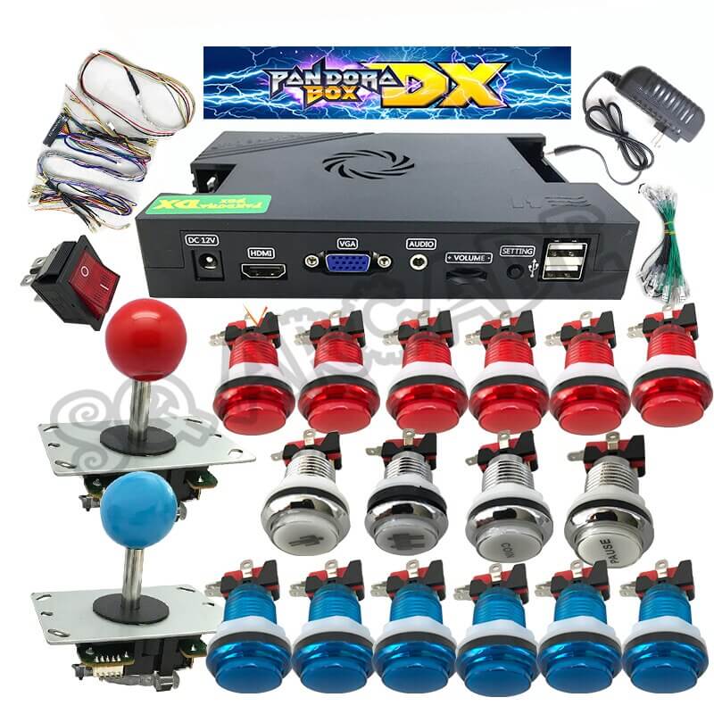
3000 In 1 Pandoras Box DX arcade kit with LED arcade button ...
Switch Offpower to the game and open the coin door. The chassis panel is accessible through the front door. The front door is held in place by the same type of latch that holds the control panel. The latch, located at the top of the front door, can be reached through the coin door. Lift the latch handle and unhook the wire fastner. Push the

Build arcade quality #joysticks for #Atari 2600, 7800, 800 ...
Joystick Arcade Game Wiring Diagram Video Game Push-button PNG - Free Download. This PNG image was uploaded on September 29, 2018, 9:57 am by user: OnStilts ...

Videos/Diagrams – Retro Active Arcade
Arcade Game Manual for Police Trainer, an arcade game by P and P Marketing, Inc. Includes parts list, set up instructions, test menu instructions, pin out diagram, wiring diagram and io schematic diagram. Part no. 780-8000-00. From P and P Marketing, Inc. 4520 W. Dickens Avenue, Chicago, Illinois 60639. (773)292-4540.
Led arcade button power supply - RetroPie Forum
Step 4: Wiring the new buttons. There are two things you need to wire to get the buttons working. First is to wire the input connection which will run directly to your JPAC (or IPAC, I'll get into that in a moment). The second is to daisy-chain the power from the existing switches to power the LEDs.
Building a Task Tracker with Arduino and LED Arcade Buttons ...
Led Arcade Button Wiring Diagram. Print the electrical wiring diagram off and use highlighters to trace the signal. When you employ your finger or follow the circuit together with your eyes, it is easy to mistrace the circuit. One trick that I use is to print the same wiring diagram off twice.

Hikig 2 Player DIY Parts Kit, LED Arcade Buttons 8 Ways Joystick and Zero Delay USB Encoder for Raspberry Pi & Windows Video Games Machine, Color: ...
Place the arcade button through the 1" hole. Secure the arcade button by screwing the nut onto the back of the arcade button. NOTE: Screw the nut with the teeth facing the arcade button (See below) Attach the blue cables to "COM Connector 3" and "NO Connector 2" (see diagram below). Snap white plastic switch back in place.
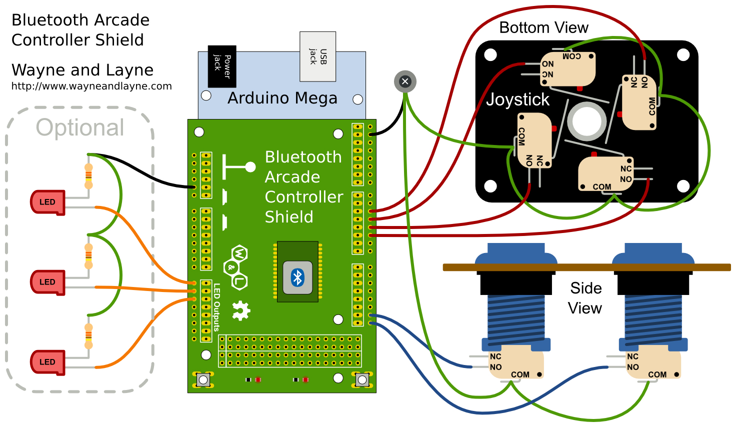
Bluetooth Arcade Controller | Wayne and Layne
Game Manuals & Schematics. If you want the entire archive, it is available in CD format at the Online Store . M = Manual, S = Schematics, L = Parts List. P = Pinouts/wiring diagram, D = Dip switch settings. Title - Company.

Hikig 2-Player LED Arcade DIY Kit for USB MAME PC Game DIY & Raspberry Pi Retro Controller DIY Including 2X Arcade Joystick, 20x LED Arcade Buttons, ...
General theory on wiring arcade switches (buttons & joysticks) Warning: This is not a terribly technical discussion. If you *really* want to understand wiring and electronics, take a look at the tutorials section on the techs & tips page, look for the electronics link. What this will attempt is a brief "how-to" on connecting up wiring to your controls.
Arcade Joystick, Button, and Interface Bundle
Feb 01, 2022 · Arcade Controls Wiring: Button Diagram Arcade Controls Wiring: Connecting to the Encoder. The arcade controls wiring wouldn’t be complete without connecting everything to the encoder board. In this section, we will cover the basics of this board, its pinout, and wiring diagrams. The zero-delay encoder does have some basic protection for ...
Junlinto 45mm Push Arcade Button 12V Power LED For Arduino ...
set to "upright/1 control" mode. [Archive] Wireing 60 in 1 pac man buttons Technical - Videogames - General Repair And Help. You can find the JAMMA wiring diagram here. I got myself a few items from jamma boards to built a 60 in 1 multi-board your xx-in-1 board manual will show you which wires are what. ..
Welcome to Ultimarc, the Ultimate in Arcade Controls.
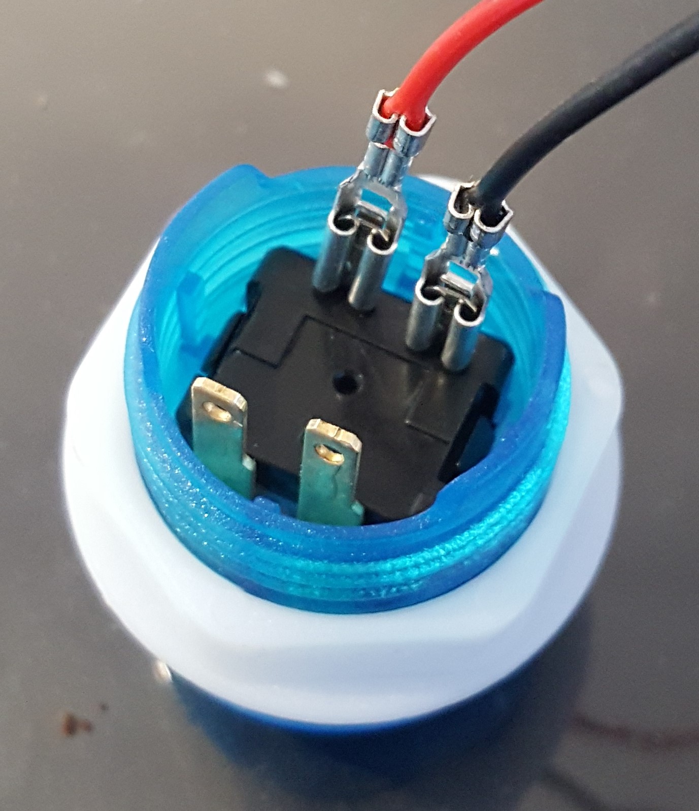
I think this diagram will work for your buttons -- related thread here. The two pin / two 0.110" Quick Disconnect wires connect to the microswitch tabs. (A and B) There should also be some "daisy-chains" for the red connectors. One daisy-chain for ground like the black wire below and one daisy-chain for 5v like the red wire below.

Mr. Armageddon's Project Log: TableTop Arcade - Wiring and ...
There is a color coded wiring diagram on the X-arcade site, also, BTW. The X-Arcade™ was designed to be used with a variety of games and MODE 1 (switch closest to the serial cable, or yellow wire on the switch itself) cannot be programmed. The mouse buttons on the Tankstick/trackball cannot be programmed.

LED Arcade Button KIT - Unboxing, Review, and HOW TO SETUP/WIRE
problem is, i cannot find a wiring diagram anywhere, and it has gotten to the point that i post a question in the forums. i would like to just use the four buttons i have installed, along with the player 1 and 2 buttons, but if i have to cut a new piece of wood, that is nothing. thanx and have a great night.

StealthSwitch3 Arcade Button Installation Info for DIY Photo ...
Diagram of how the buttons and switches are wired to the I-Pac for the ArcadeCab Control Panel Layout It is usually easiest for you to install all the joysticks and buttons in the control panel first. Then go around and add the cherry switch to each button. The joysticks should have come with

Avisiri 1 Player Arcade Buttons Joystick DIY Kit Parts ...
Jul 03, 2009 · The most common wiring setup for a microswitch is to have the ground wire on the very bottom prong (the common prong) and the action wire on the prong closest to the ground wire (the normally open prong). This will send a signal to the board whenever the button is pressed. This setup is used in the majority of arcade games that you will encounter.
Arcade Game Diy Parts 2x Zero Delay Usb Interface + 2x ...

Circuit Diagram | Arcade Button Control Box | Adafruit ...

Wiring | Arcade Button Control Box | Adafruit Learning System

StealthSwitch3 Arcade Button Installation Info for DIY Photo ...
Homebuilt Rovs
Arcade Button Layouts and Wiring 101 - YouTube

How To Wire Arcade Power Supply & Switch

Joystick Wiring Problem

Using Arcade switches with the pi3 - Raspberry Pi Forums

Buy Hikig 2 Player DIY Parts Kit, LED Arcade Buttons 8 Ways ...
Arcade Joystick and Button Kit
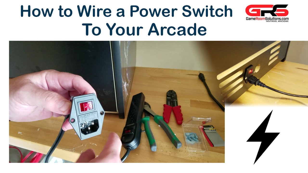
How to Wire a Power Switch to Your Arcade
Pinscape Build Guide

Hikig LED DIY Arcade Game Machine Parts Kit, 10x LED Arcade Buttons 1x 5pin Arcade Stick Zero Delay USB Encoder for PC Windows System & Raspberry Pi ...

Note: EG Starts LED Acrade Buttons Not Lighting Up? (Version ...

Building a Home Arcade Machine - The electronics | Retromash

J-ACE Arcade Controls Encoder - Share Project - PCBWay

PiRetrocade Assembly Guide - learn.sparkfun.com

ArcadeCab- MAME Cabinet Plans 2: Wiring the Control Panel
How do I get these Led Arcade buttons to light up? - RetroPie ...
Add LEDs to Your Arcade Stick Sanwa Buttons! : 6 Steps (with ...
0 Response to "37 arcade button wiring diagram"
Post a Comment