39 open center hydraulic valve diagram
Directional Control Valves | Hydraulic Valves - Surplus Center Directional Control Valves,Hydraulic Valves,Hydraulics, PRINCE MONOBLOCK VALVE Brand new PRINCE. For control of cylinders, motors, etc. Open center, Basic Hydraulic Open Center Series Parallel Connection ... Basic Hydraulic Open Center Series / Parallel Connection System Schematic. Illustrated below, shows a variation on the series-connected type. Oil from the pump is routed through the control valves in series, as well as in parallel. The valves are sometimes stacked to allow for extra passages. In neutral, a liquid passes through the valves in series, as the arrows indicate.
Open-center valves in mobile equipment | Power & Motion Apr 08, 2009 · Open-center valves are often used in mobile equipment because they accommodate fixed displacement pumps as the power source. The normal configuration is to combine several valves (spools, functions, or sections) into a sort of integrated circuit package called a valve stack.
Open center hydraulic valve diagram
Orbital Valves - Orbital Valve Information - Hydraulic ... Open Center / Non Load Sensing Note the four (4) ports marked L,R,T and P. These are the four hydraulic fluid connection ports that make the unit operate. They are as follows: P - Pump. The high pressure input from the pump T - Tank. The low pressure return line to the reservoir (tank) L - Left. Closed Center Conversion - Cross MFG This option provides for conversion from open center to closed center by blocking the open center flow passage with the closed center plug as shown. It may be used in any standard Cross SA or BA valve featuring the conversion plug/power beyond machining in the BYD port. The valve may also be ordered already converted to closed center. PDF A guide to selecting a manual hydraulic directional ... a manual hydraulic directional control valve Characteristics and configurations of manual directional control valves used in hydraulic systems - selecting the right valve for the job. Directional control valves are probably the most common of all hydraulic components and are used to control the starting, stopping and reversal of flow in a system.
Open center hydraulic valve diagram. open center valve - YouTube video explains the working principles of an open center spool valve. Schematic, Manuals, Specifications and Diagrams for ... 10-45 - hydraulic, double auxiliary valves, open center Find Related Models 100 125 150 175 200 225 250 275 300 Hydraulic Spool Valve Diagram - Valves Spool Diagram Hydraulic directional spool valve is a relative motion between the valve spool and valve housing, used for controlling fluid-flow direction of actuator motion (movement), select alternative hydraulic oil control circuits, achieve logic control function. The hydraulic spool valves target is to reach different mechanical movement of actuator ... Basic Hydraulic Open Center System Schematic Basic Hydraulic Open Center System Schematic. Open-Center System. In this system, a control-valve spool must be open in the center to allow pump flow to pass through the valve and return to the reservoir. In the illustration below, shows this system in the neutral position. To operate several functions simultaneously, an open-center system must have the correct connections, such as, series, series / parallel connection, and flow divider.
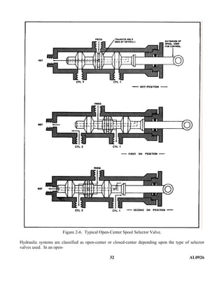
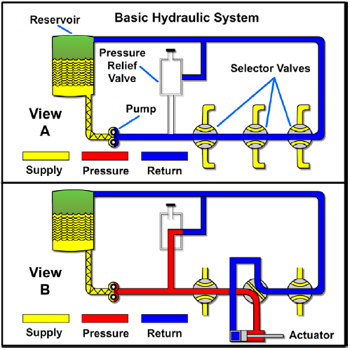
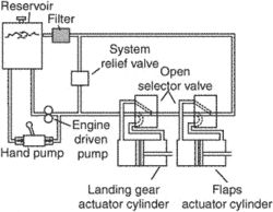
Four-port three-position directional control valve - MATLAB Description. The 4-Way Directional Valve block represents a directional control valve with four ports and three positions, or flow paths. The ports connect to what in a typical model are a hydraulic pump (port P), a storage tank (port T), and a double-acting actuator (ports A and B).Fluid can flow from the pump to the actuator via path P-A or P-B and from the actuator to the tank via path A-T ... PDF VG35EH Open-Center Directional Control Valve Hydraulic Valve Division Elyria, Ohio, USA Bulletin HY14-2007-B1/US Open-Center Directional Control Valve 1 Technical Information VG35EH Build Program General Description The VG35 has been a strong and reliable player in the 170-246 LPM (45-65 GPM) open-center, directional control valve market for many years. Now it has a new, Aircraft Basic Hydraulic Systems and Hydraulic Power Systems Open center hydraulic system When one of the selector valves is positioned to operate an actuating device, fluid is directed from the pump through one of the working lines to the actuator. [Figure 2B] With the selector valve in this position, the flow of fluid through the valve to the reservoir is blocked. Open and Closed Center Hydraulic Systems - Muncie Power Products Within an open center system, as the pump turns flow is generated and then directed back to the tank through a central passage within the directional control valve. When one of the directional control valve’s spools is stroked, the flow is focused toward a load and pressure is created. Once the pressure exceeds the load, the load moves and the hydraulic work is executed.
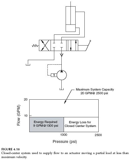
Closed Center Versus Open Center Hydraulics | Brendan ... Exhibit 3 shows a simulation of the same analytical circuit with the system on standby but with the directional control valve switched to open center. Theoretical heat-load now is 1 kW (5.2 x 120 / 600), about a third of what it was with the pump sitting on its pressure compensator setting. PDF LS DIRECTIONAL CONTROL VALVES ... - Brand Hydraulics Co. Hydraulic Kick-out Adjustment - The SH & SHA models have an adjustable single hydraulic kick out preset to 800-1000 psi. The HHA model comes equipped with a double hydraulic kick out preset to 800-1000 psi. To adjust kick-out pressure: Locate jam nut, and set screw on the spool action cap. (Opposite valve's handle) PDF Hydraulic Systems Basics - Toro hydraulic control valve. The valve shown in the illustration is a open center valve, meaning that the oil flow is returned to the reservoir when the valve is in the neutral position. The spool valve has the capability to direct fluid flow to either end of the actuator. As the spool is moved, fluid is redirected to one end or the other of the PDF C. Signature 12 - your mobile hydraulics source VES Valves PARALLEL HYDRAULIC CIRCUITS OUTLET CONVERSION PORT OPTIONS The most common type of hydraulic circuit is the par-allel circuit. Refer to the parallel circuit diagram. With all valve spools centered, the pump flow will return to tank at low pressure through the open center bypass. When a spool is actuated, the open center bypass is
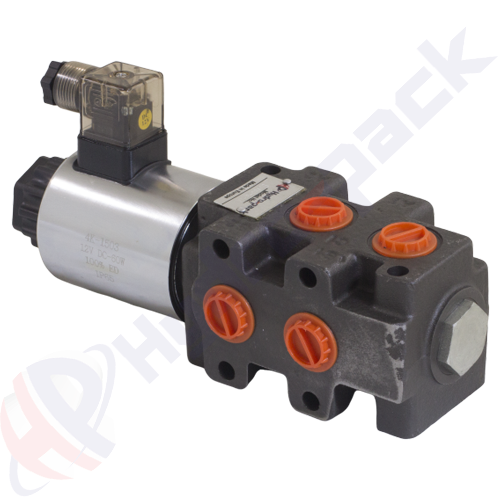
6/2 solenoid operated valve, SVV90 , one spool , G 1/2 ...
PDF Directional Control Valve Equipment for Front End Loaders It is a two-spool monoblock valve designed to be used in open center, load sensing or constant pressure hydraulic systems. The valve can also be serial connected to an Electric 6/2 Circuit Selector Valves by using a High Pressure Carry Over Adaptor (Power Beyond Sleeve). The CV152 valve has all its ports including Pump and Tank ports facing in one

Basic Hydraulics - Directional Control Valve - Blog.Teknisi
How to Connect Multiple Valves Using Power Beyond ... Open center or through center valves need to be connected in series using power beyond porting. Power Beyond allows unused flow to power multiple valve sets downstream. Power beyond also allows the designer to choose which valve sections are more important than another. In a hydraulic system, there can be multiple operator locations.

Hydraulic Four-Way Sliding Spool Valve - CAT Hydraulic ...
Hydraulic and Pneumatic P&ID Diagrams and ... - Inst Tools Fluid power system diagrams require much more complex valve symbology than standard P&IDs due to the complicated valving used in fluid power systems. In a typical P&ID, a valve opens, closes, or throttles the process fluid, but is rarely required to route the process fluid in any complex manner (three- and four-way valves being the common ...

Intro to Directional Control Valves | LunchBox Sessions
Hydraulics Systems Diagrams and Formulas - Cross MFG Winch. The diagram shows a winch powered by a hydraulic motor. The directional control valve with built-in relief features optional flow control to control the speed of the winch . The hydraulic pump and motor must be matched to the torque requirements of the winch.

How to configure mobile hydraulic valves using power beyond
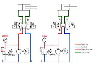
What is the difference between closed center and open ... Answer (1 of 7): Open Center refers to the open central path of the control valve, when valve is in neutral position. The hydraulic pump is continuous flow type. When valve is neutral then hydraulic fuid goes back to reservoir. As we move valve to (lets say extend actuator side) hydraulic path di...
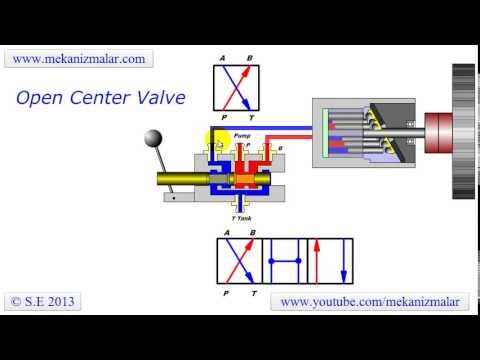
open center valve
Basic Diagrams and Systems - Engineering Library In the preceding chapters, you learned about hydraulic and pneumatic fluids and components of fluid power systems. While having knowledge of system components is essential, it is difficult to understand the interrelationships of these components by simply watching the system operate. The knowledge of system interrelation is required to effectively troubleshoot and maintain a fluid power system. Diagrams provided in applicable technical publications or drawings are a valuable aid in understanding the operation of the system and in diagnosing the causes of malfunctions. This chapter explains the different types of diagrams used to illustrate fluid power circuits, including some of the symbols that depict fluid power components. Included in this chapter are descriptions and illustrations denoting the differences between open-center and closed-center fluid power systems. The last part of the chapter describes and illustrates some applications of basic fluid power systems.
What is a Spool Valve? - Types, Configurations, Applications
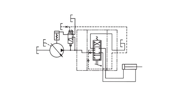
How to configure mobile hydraulic valves using power beyond Figure 2. Connection of an additional open center DCV using the power beyond facility. Most mobile directional control valves can be made closed center by plugging the drilling between the pressure and tank galleries and leaving the power beyond port plugged (Figure 3). This means that if the existing valve is closed center, supplying pump flow ...
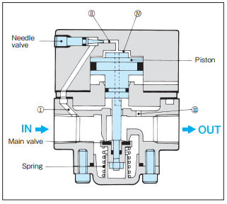
KONAN Slow-Start Valve (Quick Cylinder Extension Preventive ...
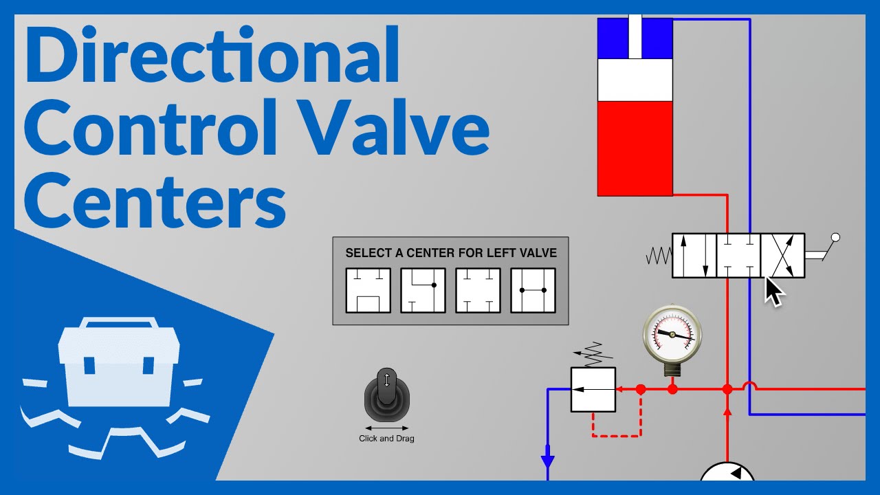
Basics of Directional-Control Valves | Power & Motion An open-center condition (Fig. 4), could be achieved simply by making all the binary valves normally open (NO) instead of normally closed. Likewise, tandem- and float-center configurations can be accomplished by using NO and NC binary valves. 4. Above are common center-spool arrangements for matching neutral-position fluid routes to the application.

Hydraulic Closed-Center System - Hydraulic & Process Valve
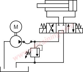
Pressure Relief Valve - Diagram , Working Pressure Relief Valve - Diagram , Working Introduction. Hydraulic energy is produced as long as the prime mover (usually an electric motor) drives the pump, and hydraulic pressure develops by resistance to pump flow.Hence, the hydraulic system suffers damage if the pump flow is not stopped or off loaded (recirculate) back to the tank during non-action periods of the circuit.Non-action ...
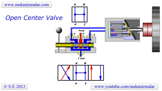
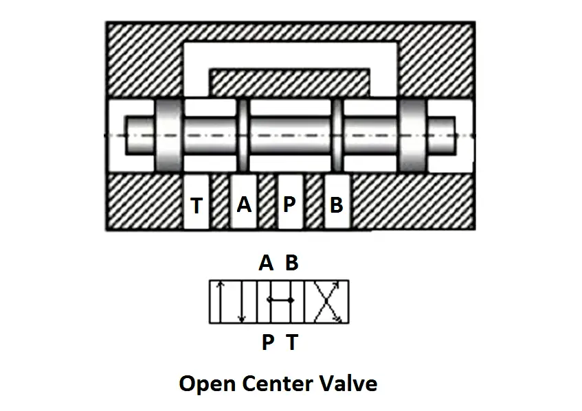
Open Center Valve
Intro to Directional Control Valves - LunchBox Sessions Positions. Most directional control valves are of a spool-type construction. The spool has lands and undercuts, housed within precision-machined casing. As the spool shifts, the lands and undercuts open and close flow paths. The example valve has 3 positions: center, straight through (P to A), and crossover (P to B).
Hydraulics, open-center, pressure compensated (PC) - 21.1 gpm
Prince Manufacturing Corporation > Support 1) All hydraulic valves must be properly installed into the hydraulic system to prevent personal injury and/or property damage. Further, the improper servicing of a valve may result in personal injury and/or property damage. Please read and understand all catalog and service information before starting.

Mariners Repository: Hydraulics Part 1 - Direction Control Valves
2 Spool 8 GPM Prince MB21BB5C1 DA Valve - Surplus Center If it is actually an open center valve, how could it be used in a loader application? A: In our use of the term, open center is used as meaning the pump flow circulates back to the tank in a continuous loop at low pressure until the spool is shifted. Closed center means the pump and tank ports are blocked in neutral.

Hydraulic Equipment Slowdown - Nailing Internal Leakage
PDF A guide to selecting a manual hydraulic directional ... a manual hydraulic directional control valve Characteristics and configurations of manual directional control valves used in hydraulic systems - selecting the right valve for the job. Directional control valves are probably the most common of all hydraulic components and are used to control the starting, stopping and reversal of flow in a system.
What is the use of a float centred 4/3 solenoid valve, and is ...
Closed Center Conversion - Cross MFG This option provides for conversion from open center to closed center by blocking the open center flow passage with the closed center plug as shown. It may be used in any standard Cross SA or BA valve featuring the conversion plug/power beyond machining in the BYD port. The valve may also be ordered already converted to closed center.

Basic Hydraulic Systems
Orbital Valves - Orbital Valve Information - Hydraulic ... Open Center / Non Load Sensing Note the four (4) ports marked L,R,T and P. These are the four hydraulic fluid connection ports that make the unit operate. They are as follows: P - Pump. The high pressure input from the pump T - Tank. The low pressure return line to the reservoir (tank) L - Left.

Prince RD522GCGA5A4B1 $418.73 Valve, 4 Way, 3/4 In NPT ...

Open-Center Hydraulic Circuit - Hydraulic & Process Valve
Hydraulic Power supply options

Flow forces analysis of an open center hydraulic directional ...
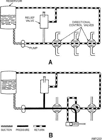
Figure 12-1.--Basic open-center hydraulic system.
Solved In the picture to the right, in hydraulic systems ...
Hydraulic Closed-Center Circuit - Hydraulic & Process Valve

SDCF Series 1-Spool Monoblock Valve With Pressure Comp. Flow Control, 4-way 3-position, Open Center Friction Detent Spool, 0-12 GPM Flow Range

Fluid Power Symbols. - ppt download
Energy-Saving Considerations and Fixed Pump Unloading - Fluid ...
Hydraulic systems-and-components

Ospc-160 Open Center Hydraulic Steering Unit - China ...
Basic Diagrams and Systems | Engineering Library

Hydraulic Open-Center System - Hydraulic & Process Valve

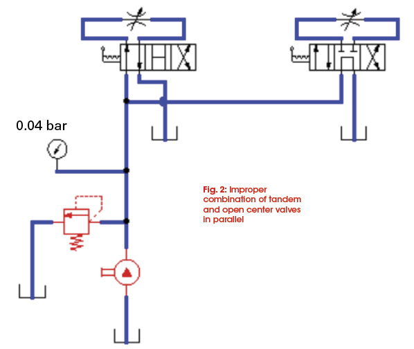
Understanding parallel connected valves | Power & Motion

Basic Hydraulic Open Center Series Parallel Connection System ...
Open-center hydraulic system | Article about open-center ...

Hydraulic Open-Center System - Hydraulic & Process Valve

Basic Hydraulic Systems
Directional Control Valve Centers
Tandem center vs Open center valves - TractorByNet

Hydraulic machinery - Wikipedia
Open and Closed Center Hydraulic Systems
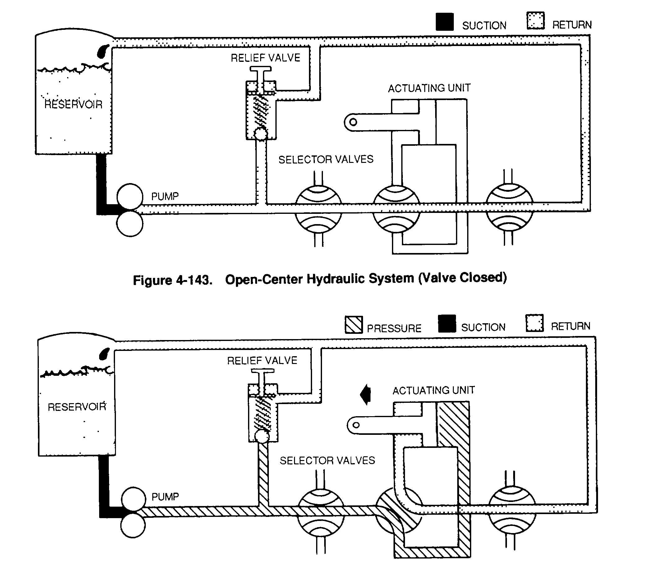
Figure 4-143. Open-Center Hydraulic System (Valve Closed)
0 Response to "39 open center hydraulic valve diagram"
Post a Comment