39 sump pump piping diagram
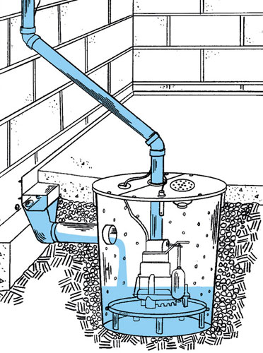
SUMP PIT UNION CHECK VALVE JUNCTION BOX AND WIRING BY DIVISION 16000 GRATING PIT FLOOR SUMP PUMP 1-1/4" 2" SUMP PUMP DETAIL P0.01NOT TO SCALE 2 P0.01 LEGEND, SCHEDULES AND NOTES - PLUMBING PLOTTED: Drawn: Checked: Approval: Date: Project #: 2555 Temple Trail, Winter Park, FL 32789 (407) 629-0595 www. fuglebergkoch.com BR569 REVISION HISTORY ... In this video, watch the Ninjas install a pop-up drain for the sump pump and dehumidifier!Purchase DIY Products - https://diy.crawlspaceninja.com/Free Assess...
heavy grade poly pipe are also available and are much lighter and easier to work with. 12. Position a torque arrestor directly above the top of the pump. This will center the pump in the well and keep the pipe from twisting due to torque created by the pump motor. 13. IMPORTANT! Wire splices should be staggered, securely crimped and weatherproof.
Sump pump piping diagram
The final chamber always holds your return pump which is the heart of your tank, delivering water from the sump back into the display aquarium via the return pipe. Every tank needs a power center or surge protector mounted within a reasonable distance of the sump for plugging in the equipment. This is a simple, working plumbing grid for your basic flow needs with a little bit of expandability included. However, if you plan to run more than just a display tank-sump loop through your return pump, I encourage you to try the advanced plumbing scenario. 2. Plumbing build with two return pump - fed media reactors and dual outlets. the submersible turbine pump head, piping, line leak detectors, interstitial monitoring devices, wiring, and other equipment. You generally will find turbine sumps directly above your USTs. Turbine sump lids generally range from 3 to 4 feet in diameter and can be round, oval, square, or rectangular in shape. Dispenser Sumps
Sump pump piping diagram. Sump Pump Piping Diagram. Posted on by. Visit SumpPumpRatings.biz for news & tips about all types of sump pumps…. Pump Installation And Service Manual HYDROMATIC. Possible septic sump. Pump Description: The Hydromatic pumps covered by these instructions are Pump air bound 2. Discharge head too high 3. Two Types of Sump Pump Installations - Simplex and Duplex Pumps. A sump pump is normally installed in a pit at the low end of a basement or crawl space floor or in another location where water needs to be removed such as in a boiler pit or an outdoor well pit. On occasion we find that we need to install two or more sump pumps inside or outside ... all duplex sump pumps except for the sis/css pump compartment sump pumps have alternators which start each pump alternately. test connections are attacheo to bottom of piping to facilitate draining of lines. this vent piping is terminated in an area of good circulation. all instruments shown on this diagram are The pumps usually consist of a packaged unit that is supplied with all control and a set of run and standby pumps [2 pumps]. Storage Tank - A water storage tank is often used to allow the make up water to be stored and also to provide an air gap / break between the the system and if connected to a fresh water mains supply to stop backwash ...
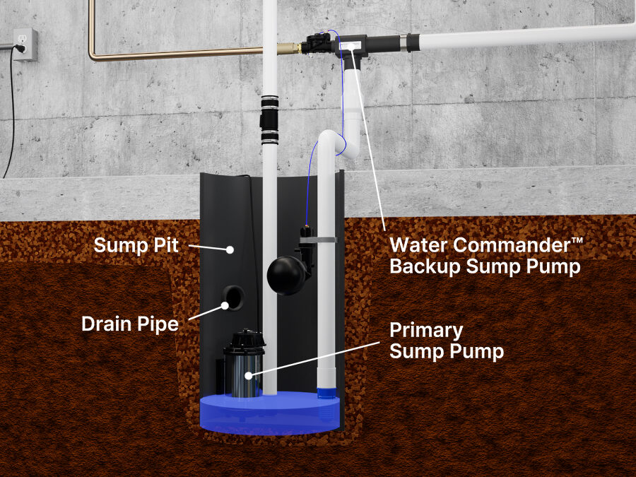
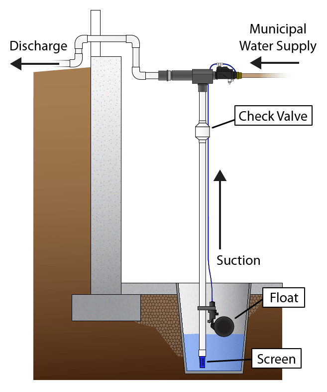
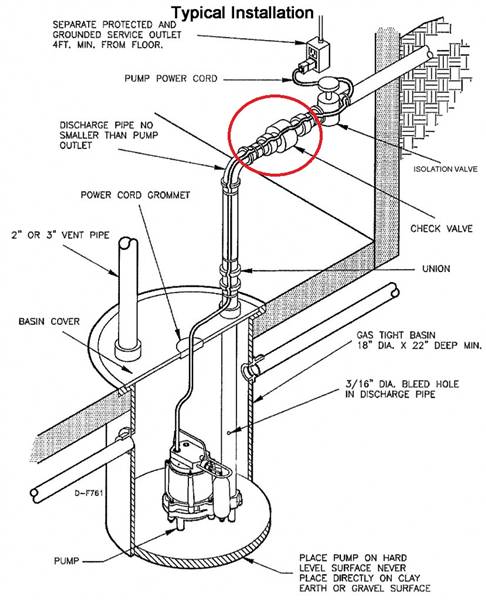
All elevator pits for elevators that have Firefighters' Emergency Operation shall have a drain or sump pump in accordance with ASME A17.1 Section 2.2.2.5. The drain or sump pump discharge shall be into the sanitary or storm drainage system through an indirect waste connection. The elevator pit discharge system is not required to include an oil separator, except as required by section 1003.4. The diagram below illustrates a basic Water Commander ™ water-powered sump pump installation common in many homes. The pump has to be connected to your home's water supply, generally a 3/4″ or 1″ line. A suction pipe descends from the pump into the sump pit, while a discharge pipe brings the water out of the home. GUIDELINES FOR PUMP SYSTEM DESIGNERS Jacques Chaurette p. eng. www.pumpfundamentals.com August 2011 Synopsis The following is a list of potential problems areas or simply just good design practice that the author has applied and encountered over the years. They deal mainly with piping issues that affect pump performance. 1. Diagrams --Typical Pump Installations. The information provided here is for educational purposes only. Technically qualified personnel should install pumps and motors. We recommend that a licensed contractor install all new systems and replace existing pumps and motors. Failure to install in compliance with local and national codes and ...
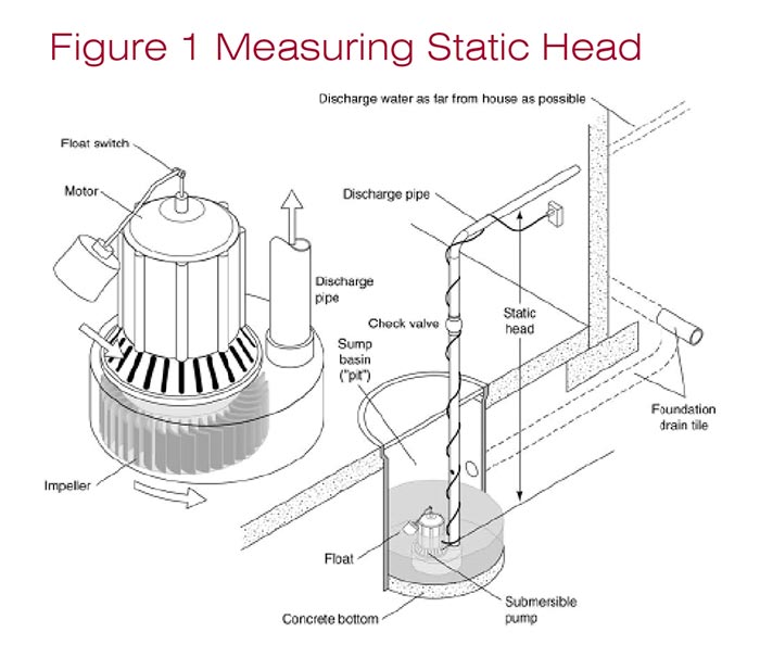
Dry Sump Plumbing Diagram. Title: Tech-DrySumpPlumb Created Date: 12/6/2016 2:43:13 PM ... A Sump Pump Check Valve. The sump pump check valve is a section of the discharge line (black, in the photo to the right). Its purpose is to prevent water that's been pumped into the discharge line from washing back down into your sump pit. Say that your system has eight feet of 1 ½" pipe leading straight up from your sump pump before bending ... Include a free body diagram. A pump draws water from a sump through a vertical 6′′ pipe. The pump has a horizontal discharge pipe 4′′ in diameter that is 10.6 ft above the water level in the sump. While pumping 1.25 cfs, gages near the pump at entrance and discharge read —4.6 psi and +25.6 psi, respectively. A Sump Pump System The Sump Pump of pipe is 22 feet. 3 Step 4. Put it All Together To figure out Friction Head, add the actual length of the discharge pipe to the equivalent length of pipe from fittings. Then multiply by the friction loss and divide by 100.
Sump Pits: Introductory Guide • Water Commander™
Assemble the PVC piping from the sump pump outlet through your home's rim joist. Most pumps use 1.5" PVC pipe, but review the instructions that came with your pump to be sure. Leave a short stub of PVC pipe on the outside, you can attach a flexible hose to go the rest of the way.

Backup Sump-Separate Discharge? | Terry Love Plumbing Advice ...
The same thing can be said about the size of the sump pump discharge pipe. The usual diameter of the discharge pipe is 1.25" to 1.5". Anyone with basic knowledge on how sump pump works, knows that, sump pump works the best when the discharge line diameter is large enough to carry the water out. With reduced size comes less efficiency.

Sump Pump Systems - Foundation King
The Sump Pumps Direct experts teach you how to cut and glue PVC pipe step-by-step like the professionals. Learn which tools you need to do the job by following our easy-to-understand how-to guide. Get expert advice on how to accomplish this simple DIY project.

Submersible Well Pump Accessories Installation Diagram
from exiting the pit and damage the pump if the line freezes. (see Diagram A) The system should be placed on a flat surface free from dirt and debris. If the bottom of the sump pit is not clean, remove as much of the debris as possible. You should place a pump stand or bricks on the floor of the sump pit to raise the pump above the debris.

Sump Pump and Ejector Pump | Nations Home Inspections, Inc
Consult the wiring diagrams on pages 4, 5 and 6 for the proper way to connect the pump and controls. ALIGNMENT Weinman sump pumps and sewage ejectors are precision built for perfect alignment. The entire units is aligned through use of male and female fi ttings on the column pipe and its mating pieces.
Basement Watchdog Backup Sump Pump System Installations ...
The sizing diagram below is valid for pump stations up to four pumps, all of which may be duty pumps. Tolerances of -10% on the sump dimensions are acceptable provided that the combined effect of the departures does not lead to velocities significantly higher than those for the standard sump. Flow per pump refers to the pump duty point when one

PumpSpy Dual Pump Install Kit
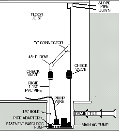
Backup Sump Pump System installed by someone else, you must read ... your needs from the diagrams at the right. Full instructions for each installation method are provided on the following pages. Installation will take a couple hours. Page 3 NORMAL SUMP PIT INSTALLATIONS PUMP WIRE PIPE ADAPTER FLOOR JOIST MAIN AC PUMP RIGID 1-1/2" PVC PIPE ...

Sump Pump Installation | Plumbing | Fairfax VA | HVAC
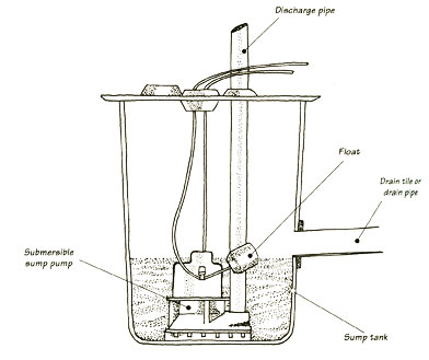
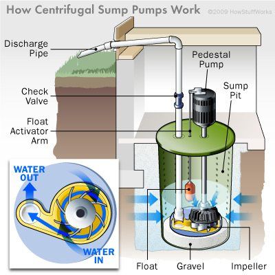
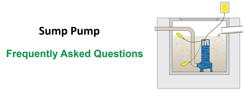
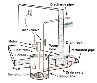
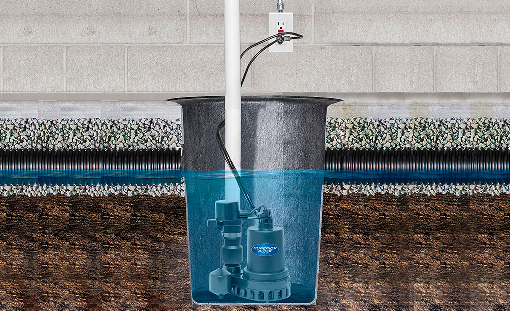
A sump pump will keep water out of your basement. This shows how a sump pump works, with parts diagram and information on submersible and pedestal sump pumps. A sump pump system consists of four major parts: a ground water collection system, a sump tank, a pump, and an outlet drain. Here's how they work:
How to Install or Replace a Sump Pump - HomeTips
Throw old sump pump away. 5 Tighten pipe assembly back into new sump pump. 6 Reinstall check valve on the outlet side of the discharge piping; 7 Place sump pump back inside pit. If piping is too long, measure length to be trimmed by lining up pump and piping next to outlet discharge piping with check valve.

Professional Sump Pump Installation and Pumping Systems in CT ...
Sump Pump Installation Guide: A step-by-step explanation on How To Install A Primary Sump Pump. Our product experts walk you through how to install a primary sump pump with easy to understand step-by-step guidance. You don't need to hire a contractor to replace your sump pump. Watch the video and read the steps anyone can follow so you can accomplish this DIY project.
Sump Pump Repair Richmond VA | Fast, Same Day Service
The pump shall be fitted with an adapter fitting that easily connects to/disconnects from the discharge fitting as the pump is raised from or lowered into the sump. The discharge piping shall connect to the discharge fitting so that it is disconnected without workers entering the pit. Where the sump depth is greater than five feet or other ...

Sump Pump Services Akron, Ohio | Northeast Ohio Plumbers
the submersible turbine pump head, piping, line leak detectors, interstitial monitoring devices, wiring, and other equipment. You generally will find turbine sumps directly above your USTs. Turbine sump lids generally range from 3 to 4 feet in diameter and can be round, oval, square, or rectangular in shape. Dispenser Sumps

Understanding Sump Pumps - Donan - Forensic Engineering Experts
This is a simple, working plumbing grid for your basic flow needs with a little bit of expandability included. However, if you plan to run more than just a display tank-sump loop through your return pump, I encourage you to try the advanced plumbing scenario. 2. Plumbing build with two return pump - fed media reactors and dual outlets.

Cost to Install a Sump Pump | Sump Pump Prices
The final chamber always holds your return pump which is the heart of your tank, delivering water from the sump back into the display aquarium via the return pipe. Every tank needs a power center or surge protector mounted within a reasonable distance of the sump for plugging in the equipment.
Sump Pump FAQs - Paul Bunyan Plumbing & Drains

What Is A Sump Pump & How Do Sump Pumps Work? | Expert Advice
Installing a Sump Pump - Build, Set-up & Install

Sump Pump Problems - Concord Carpenter

Sump Pump and Ejector Pump | Nations Home Inspections, Inc

What to do if Sump Pump Fails - Basement Water Restoration ...
How Does it Work? • Water Commander™ Backup Sump Pump

Venting a Sewage Ejector Tank | JLC Online
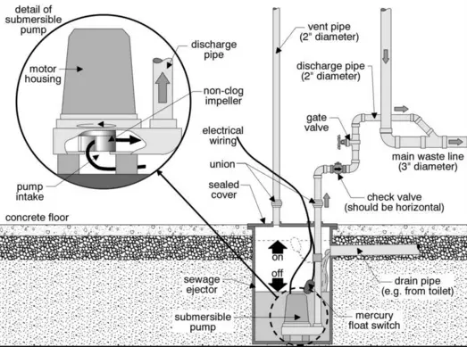
Sewage Sump Pump Installation - Plumbing HelpPlumbing Help

Sump Pump Installation - Fante's Plumbing Heating and Air
PPS-MERIDIAN\am\VAULT,D-MSUEAS01,P-AMCONTEXT_2\CONSTRUCTION ...
Sump Pump Maintenance: How to Keep Your Basement Dry (+ ...

How To Install A Sewer Ejector System

Sewage pump plumbing layout - DoItYourself.com Community Forums

Choosing the Right Sump Pump | WAYNE Pumps

What is the purpose of a sump pump? | Plumbing | kctv5.com
Sizing Up a Sump Pump | WATERPROOF! Magazine

Sump Pumps • Sump Pump Service • NJ • A Rooter Pros
Common Sump System Problems, WI Home Inspections by Capitol ...

Sump pit drainage systems - Residential Lot Grading ...

Is Your Sump Pump Ready For Spring? - Valu Home Centers | For ...
The Benefits of a Sump Pump - Schuelke Plumbing

Foundation Drain Collector Sump Pump Subsidy - City of ...
Best Sump Pumps for Your Basement or Crawlspace
What Is A Sump Pump & How It Works? | Water Guard Plumbing
0 Response to "39 sump pump piping diagram"
Post a Comment