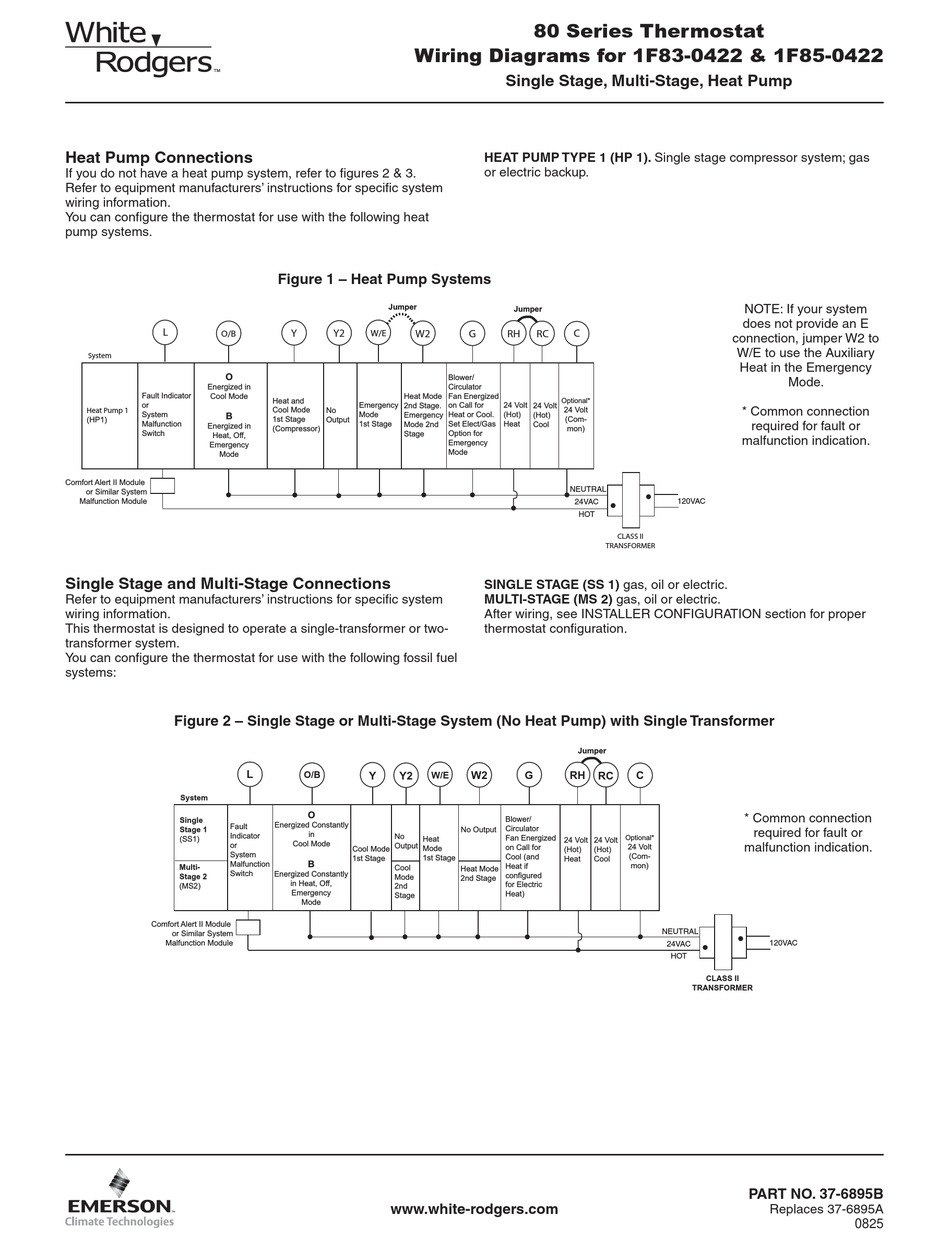
39 white rodgers wiring diagram
Thermostat Wiring Colors Code Easy HVAC Wire Color Details 1 In either case, it is crucial to find the wiring diagram for the unit. Finally, this way, you can match up the appropriate wire color coming from the thermostat to what it controls in the equipment. The red wire should always come from the hot side of the 24-volt transformer. White Rodgers 90 113 Wiring Diagram - schematron.org WHITE-RODGERS The 25M series gas control is a compact, multifunctional valve, with a direct-acting TYPICAL WIRING DIAGRAM FOR MODEL 25M APPLIANCE VALVE TYPICAL WIRING DIAGRAM FOR MODEL 25M MANIFOLD VALVE Typical Wiring Diagrams. 6 25M GAS CONTROL PRODUCT INFORMATION 30 40 50 60 70 80 90 Pressure Drop ("W.C.) X 2.
White Rodgers Type 91 Relay Wiring Diagram - easywiring A wiring diagram is a streamlined standard pictorial representation of an electrical circuit. Click on the image to enlarge and then save it to your computer by right clicking on the image. Thermostat wiring details connections for the white rodgers brand of room thermostats. If not the arrangement won t work as it should be.
White rodgers wiring diagram
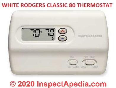
PDF Integrated Wiring and Furnace Controls Configuration TYPICAL SYSTEM WIRING DIAGRAM The 50A65-843 is an automatic gas interrupted ignition control that employs a microprocessor to continually monitor, ... 201. The 50A65 has only one serviceable part-an automotive type fuse, which protects the low voltage transformer from White Rodgers Zone Valve Wiring Diagram The old t'stat had red-to-red, white-to-white and the green wire attached to the Y terminal on a Honeywell series 20 t'stat. White Rodgers Zone Valve Wiring Diagram - If you have a White-Rodgers heat pump and thermostat system, or an Emerson thermostat, the wiring likely follows a particular pattern. White Rodgers Thermostat Np110 Wiring Diagram White-Rodgers is a leading manufacturer of thermostats, valves, controls and system protectors for the heating, air conditioning, and refrigeration industry. Thermostat wiring schematics: this article provides room thermostat wiring diagrams for Flair, Honeywell, White Rodgers and other thermostat brands.
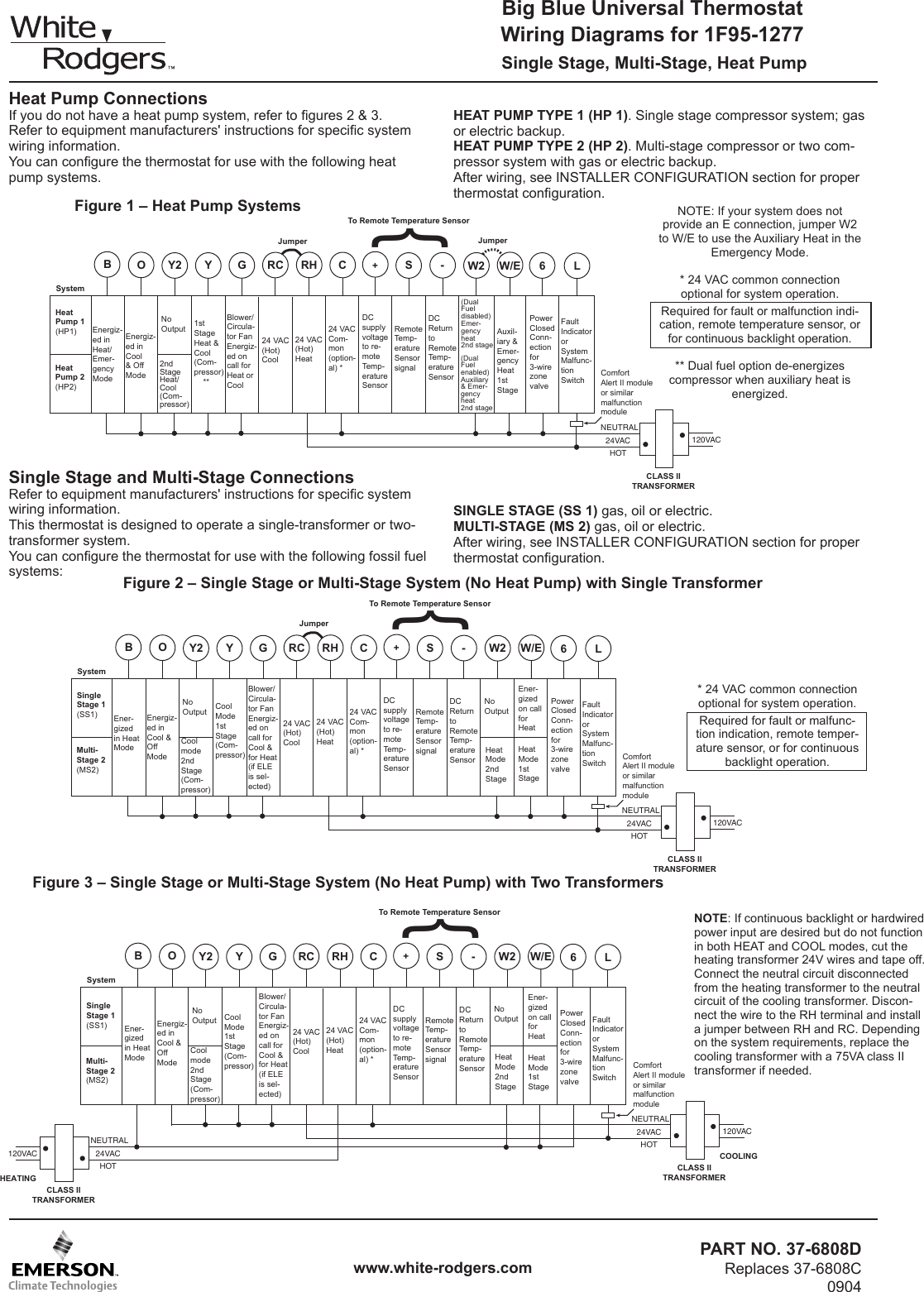
White rodgers wiring diagram. PDF Big Blue Universal Thermostat Wiring Diagrams for 1F95-1277 Wiring Diagrams for 1F95-1277 PART NO. 37-6808D Replaces 37-6808C 0904 Single Stage, Multi-Stage, Heat Pump White-Rodgers is a division of Emerson Electric Co. Printed In U.S.A. Heat Pump Connections If you do not have a heat pump system, refer to figures 2 & 3. Refer to equipment manufacturers' instructions for specific ... PDF Residential Zone Valves Wiring 298 technical help residential zone valves to auxiliary circuit for operating burner and/or circulator. (note: if same trans-former powers both the auxiliary circuit and the water valve, connect auxiliary cir-cuit to terminals 1 and 3 instead of 2 and 3.) transformer internal wiring external wiring motor holding contact ... Installation - White Rodgers 36C03-300 Gas Valve ... White Rodgers 36C03-300 Gas Valve manual : Installation. ... All wiring should be installed in accordance with local and national electrical codes and ordinances. ... The typical wiring diagram shows only the terminal identification and wiring hook up. Always refer to ... White Rodgers Relay Wiring Diagram Sample Wiring Diagram For White Rodgers Thermostat Best Wiring Diagram A Novice s Overview to Circuit Diagrams A first look at a circuit diagram may be confusing, however if you can review a train map, you can check out schematics.
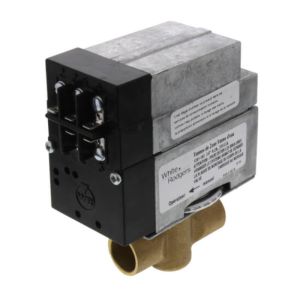
White Rodgers 3 Wire Zone Valve Wiring Diagram We include wiring diagrams and installation instructions for most zone valve model and Priority Operation: When zone 3 is switched to the priority setting and is The Load wire is taken to Terminal #1 on the White Rogers zone valve so that. I previously had (2) 3 wire, white Rodgers zone valves hooked up with no zone controller. Here is the ... Guide to wiring connections for room thermostats [7] White Rodgers 1F90 Low Voltage Digital Comfort-Set thermostat Installation Instructions, PN 37-3654, White-Rodgers Division, Emerson Electric Co., 9797 Reavis Rd., St. Louis MO 63123 [8] "Automatic Oil Burner Controls - Thermostats", Domestic and Commercial Oil Burners, 3rd Ed., Charles H. Burkhardt, McGraw Hill, 1969 (and later editions ... Aquastats: Diagnosis, Repair, Setting & Wiring Heating System ... Also see WHITE RODGERS CONTROLS - all. On 2021-04-17 by Don Hardcastle - plumbing company wants to replace the White Rodgers zone valves with Honeywell zone valves. My Aquastat L8148A sometimes makes a loud humming type sound. It appears to be coming from the switch relay. When I push the relay the noise stops. White Rodgers Gas Valve Wiring Diagram - Wirings Diagram As stated earlier, the lines at a White Rodgers Gas Valve Wiring Diagram signifies wires. Sometimes, the wires will cross. But, it does not mean connection between the cables. Injunction of 2 wires is usually indicated by black dot on the junction of 2 lines.
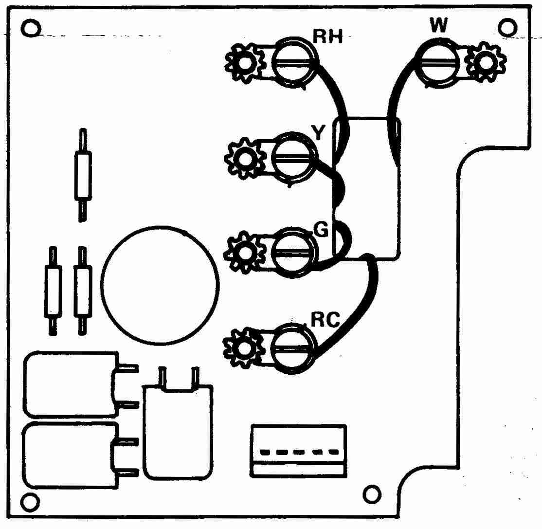
White Rodgers thermostat Wiring Diagram 1f79 Download ... Size: 191.46 KB. Dimension: 800 x 600. DOWNLOAD. Wiring Diagram Sheets Detail: Name: white rodgers thermostat wiring diagram 1f79 - White Rodgers thermostat Wiring Diagram Lovely White Rodgers thermostat Wiring Diagram Best Diagram Download. File Type: JPG. Source: capecodcottagerental.us. Size: 671.35 KB. PDF WHITE-RODGERS Fan & Limit Control - Emerson Electric Any attempt to re-calibrate this control will void the White-Rodgers warranty. Do not use on circuits exceeding specified volt-ages. Higher voltages will damage control and could cause shock or fire hazard. If in doubt about whether your wiring is millivolt, low or line voltage, have it inspected by a quali- How Wire a White Rodgers Room Thermostat, White Rodgers ... White Rodgers Thermostat Wiring Diagrams & Drawings. The White Rodgers 1F90 and similar models will replace most 2-wire heating thermostats and many 3-wire & 4-wire thermostats used for both heating and cooling. It is not used on systems without a transformer or relay, hot water heat systems that use 3-wire zone valves, two-stage heating or ... White Rodgers 1311 102 Wiring Diagram Sample - Wiring ... white rodgers 1311 102 wiring diagram - What is a Wiring Diagram? A wiring diagram is a simple visual representation with the physical connections and physical layout associated with an electrical system or circuit.
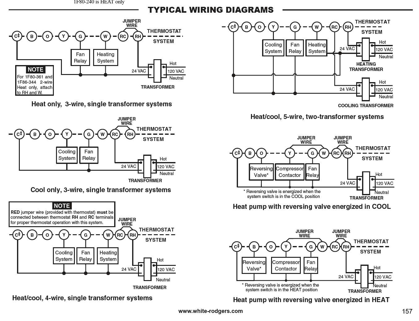
PDF 90 Series Typical Wiring 56 TECHNICAL HELP RH 24 VAC 120 VAC Hot Neutral THERMOSTAT SYSTEM G W Figure 1. Typical wiring diagram for heat only, 3-wire, single transformer systems TRANSFORMER Heating System Fan Relay Y RC JUMPER WIRE RED jumper wire (provided with thermostat) must be connected between thermo-stat's RH and RC terminals for proper ...
White Rodgers Fan Center Relay Wiring Diagram White Rodgers Fan Center Relay Wiring Diagram. By Admin | November 30, 2017. 0 Comment. Fan control center relay amp transformer 90 112 thru 130 manualzz honeywell l4064b combination and limit how to set the temperatures limits on furnace switch i m trying replace my white rodgers s84 17 with its replacement rogers wires 113 arnold s service ...
White Rogers Thermostat Wiring Diagram - Wirings Diagram There are two things that will be present in any White Rogers Thermostat Wiring Diagram. The first component is symbol that indicate electric component from the circuit. A circuit is usually composed by various components. Another thing which you will locate a circuit diagram could be traces.
PDF 36C WIRING INFORMATION - SupplyHouse.com 36C WIRING INFORMATION TECHNICAL HELP 173. 36C WIRING INFORMATION Fig 12 PILOT ADJ. S L COM. Fig 13 PILOT ADJ. S L COM. Fig 14 Fig 15 PILOT (REDUNDANT) C MAIN PRESSURE SWITCH ON/OFF SWITCH 2 1 4 3 FLAME ... 174 TECHNICAL HELP. Title: White-Rodgers_catalog_R-4320.indd
White Rodgers Lr27935 Wiring Diagram On the old white the wires are: G=green, Y=yellow, E=pink, B=blue, X1 and X2 are the same black wire, L=orange, W2=white and R= red.5/5. Download White rodgers Thermostat PDF manuals. User manuals, White rodgers Thermostat Operating guides and Service manuals.Wiring diagram for white rodgers lr - FixyaWiring diagram for white rodgers lr - Fixya
White Rodgers Furnace Control Board Wiring Diagram ... Thermostat Wiring Diagrams White-Rodgers shows a slightly different type of wiring diagram that mirrors a ladder logic diagram. WIRING DIAGRAM-UD WIRING DIAGRAM-DD SCR 8-18 AB HXW 3/8 S TIE-CABLE IGNITER BRACKET Use these instructions when replacing the following Integrated Furnace Controls IFC , Replacement Description White-Rodgers Trane Part No.
PDF WHITE-RODGERS DC PRODUCTS Type 120 solenoid WHITE-RODGERS DC PRODUCTS R-4002C 1233 GENERAL DATA Dielectric Strength • 500 Volts ... CIRCUIT DIAGRAM CIRCUIT DIAGRAM R-4002C 1233 APPLICATION NOTES ... A Wiring Diagram (Terminal Identification) B Coil C N.O. Contacts D.C. POWER CONTACTOR SERVICE INSTRUCTIONS CONTACTEUR C.C.
White Rodgers Gas Valve Wiring Diagram - Wiring Diagram White Rodgers Gas Valve Wiring Diagram | Wiring Library - White Rodgers Gas Valve Wiring Diagram Wiring Diagram consists of several detailed illustrations that display the connection of assorted items. It includes instructions and diagrams for various kinds of wiring methods and other things like lights, home windows, and so forth.
Pressure Management Regulators and Valves - Fisher, TESCOM ... Pressure reducing and backpressure regulators, automatic recirculation valves (ARC), steam traps, pad / depad valves, and relief valves for natural gas, process liquids, steam, and liquid propane.
PDF Installation Instructions for Heating & Air Conditioning IF79 MOUNTING AND WIRING CONTINUED FROM SECOND PAGE 4 E L R 24 VAC 120 VAC Hot SYSTEM MONITOR SWITCH Neutral THERMOSTAT SYSTEM G W2 Figure 2. Typical wiring diagram for single transformer systems TRANSFORMER (Class II) Changeover Relay* O/B Y C Compressor Contactor * Changeover Relay is energized in COOL when O/B switch is in ...
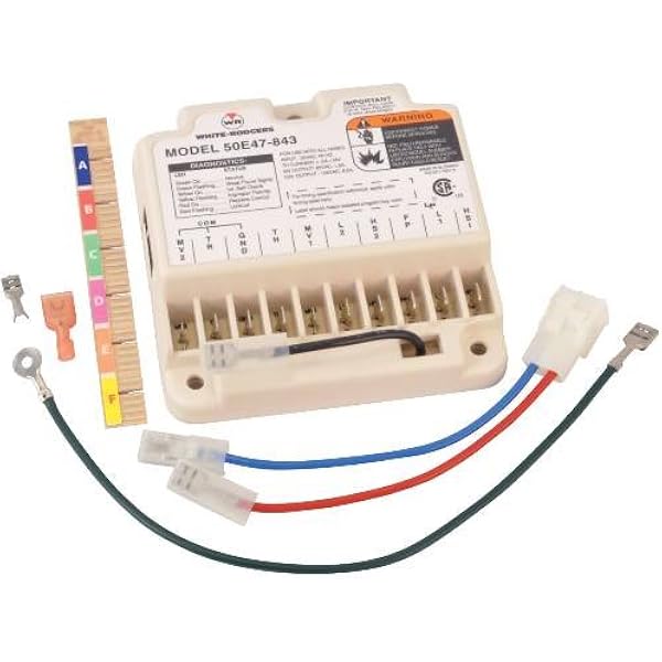
PDF 50E47-843 TECHNICAL WIRING HELP - graycoolingman.com Honeywell Robertshaw Old White-Rodgers Terminal Function S89 / S890 Terminal HS780 Terminal 50E / F47 Terminal 50E47-843 Burner Ground Connection GND (BURNER) a TR ... WIRING L2 must be grounded 204 TECHNICAL HELP. TECHNICAL HELP 50E47-843 OPERATION & TROUBLESHOOTING M V 2 T R G N D H M V 1 L 2 F P L 1 H S 1 THERMOSTAT OR ...
Hot Water Boiler Piping Zone Valves Wiring Diagram Quality 1 Wiring controls can be simple and they can be complex. If you don’t get it right it won’t work and you will blow a transformer. For someone who has wired many, many controls take some advice. First, read the instructions and get a picture of the wiring in your head. Understand the function of the devices you are wiring and the control sequence.
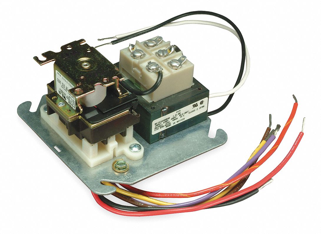
White Rodgers 90 113 Wiring Diagram White Rodgers - Fan Control Center, VAC Primary 24 VAC Secondary, SPDT Relay - Transformer and Relay Combination for Easy Installation on a. I'm replacing a White Rodgers Fan Control on my furnace. The original heater diagram shows one side black v but I can't figure where Black from relay goes where the black for transformer goes 3 wires in ...
DeltaV Controllers and I/O | Emerson US - Emerson Electric Liquid Analysis Wiring Diagram. AVENTICS CAD search. See All. ... White-Rodgers. Industries. ... wiring, changing, updating and expanding a process automation project ...
White Rodgers Gas Valve Wiring Diagram : Valves - White ... White Rodgers Gas Valve Wiring Diagram : Valves - White Rodgers Gas Valve - 3 - Page 1 36c wiring information gas valves 3 terminal panel fig.. A heat pump thermostat will use the orange wire for the reversing valve in the condenser. View thermostat white rodgers 1311 installation instructions online or download in pfd format.
White Rodgers Zone Valve Schematic - wireschema.com The White Rogers zone valves have three wires, white red and green. NJ Trooper can probably make a wiring diagram better than I. I have Rodgers 3-wire zone valve and have old Rodgers 3 wire mercury Seems like the diagram for Gas, Oil, or electric heat (1st diagram on page 3).
White Rodgers 50t35 730 Wiring Diagram - justussocializing.org White Rodgers 50t35 730 Wiring Diagram- One of the most difficult automotive fix tasks that a mechanic or fix shop can put up with is the wiring, or rewiring of a car's electrical system.The trouble in point of fact is that all car is different. next a pain to remove, replace or repair the wiring in an automobile, having an accurate and detailed White Rodgers 50t35 730 Wiring Diagram is ...
White Rodgers Thermostat Np110 Wiring Diagram White-Rodgers is a leading manufacturer of thermostats, valves, controls and system protectors for the heating, air conditioning, and refrigeration industry. Thermostat wiring schematics: this article provides room thermostat wiring diagrams for Flair, Honeywell, White Rodgers and other thermostat brands.
White Rodgers Zone Valve Wiring Diagram The old t'stat had red-to-red, white-to-white and the green wire attached to the Y terminal on a Honeywell series 20 t'stat. White Rodgers Zone Valve Wiring Diagram - If you have a White-Rodgers heat pump and thermostat system, or an Emerson thermostat, the wiring likely follows a particular pattern.
PDF Integrated Wiring and Furnace Controls Configuration TYPICAL SYSTEM WIRING DIAGRAM The 50A65-843 is an automatic gas interrupted ignition control that employs a microprocessor to continually monitor, ... 201. The 50A65 has only one serviceable part-an automotive type fuse, which protects the low voltage transformer from
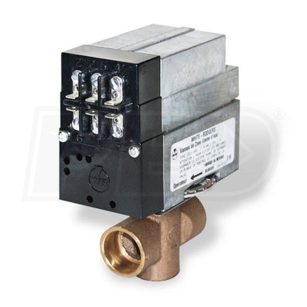
White Rodgers 1311-104 3-Wire Hydronic Zone Control, 24V with Screw Terminal Wiring Panel & AUX Switch, 1-1/4" Tubing ID













0 Response to "39 white rodgers wiring diagram"
Post a Comment