41 impulse brake controller wiring diagram
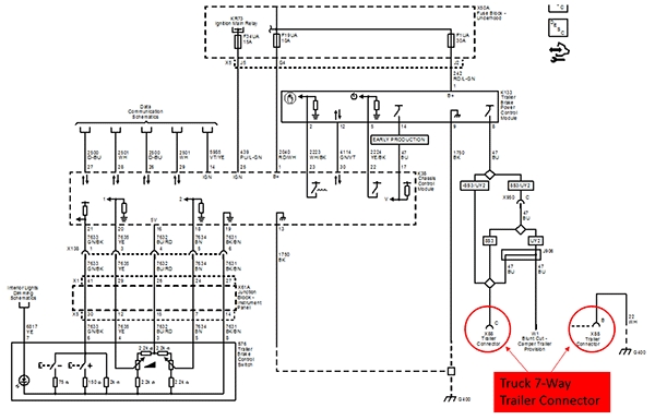
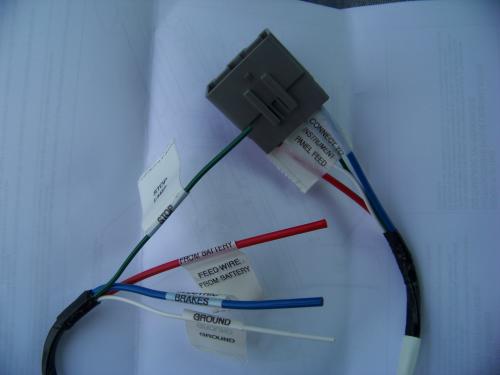
Impulse Trailer Brake Controller Wiring Diagram - Database ... Impulse Trailer Brake Controller Wiring Diagram from static-assets.imageservice.cloud Print the wiring diagram off plus use highlighters to trace the signal. When you make use of your finger or perhaps the actual circuit with your eyes, it is easy to mistrace the circuit. 1 trick that We 2 to printing a similar wiring plan off twice. Hopkins Brake Controller Wiring Diagram - easywiring Hopkins impulse brake controller wiring diagram wiring diagram is a simplified welcome pictorial representation of an electrical circuit it shows the components of the circuit as simplified shapes and the capability and signal connections amid the devices.
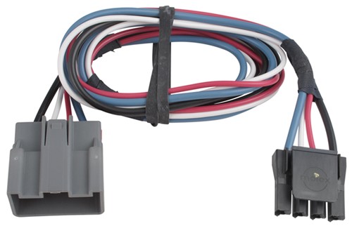
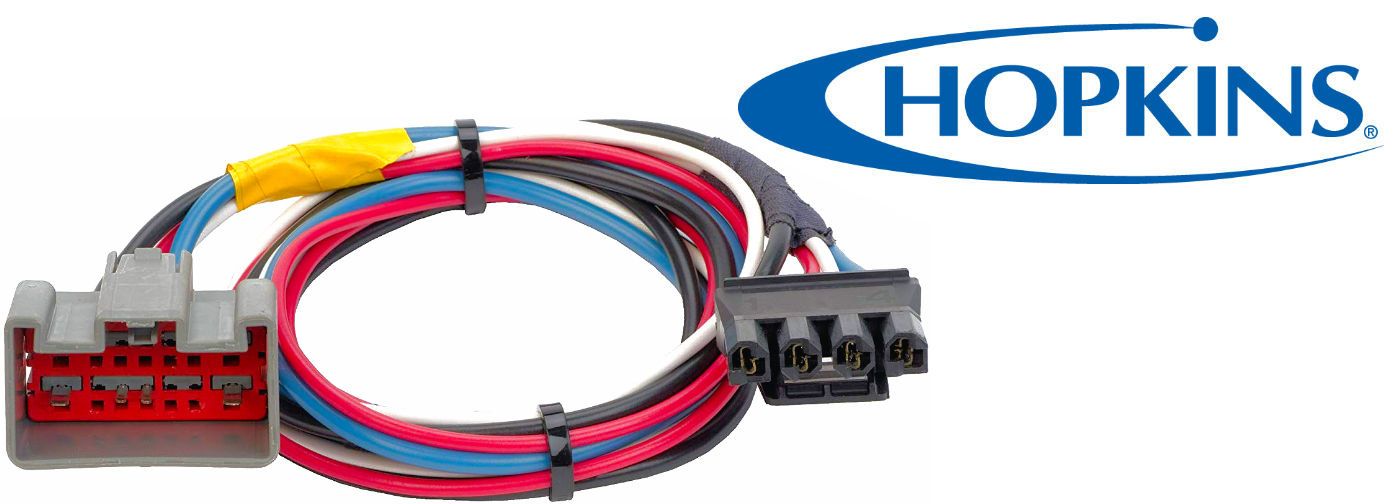
Impulse Trailer Brake Controller Shows Inconsistent ... Brake Controller Wiring Harness Port and Installing a 7-Way Trailer Connector, 2001 Chevy Silverado Troubleshooting Hopkins Impulse Brake Controller That Causes Brakes to Always Lock Which Brake Controller Wiring Harness Fits a 1997 Ford F-150

Impulse brake controller wiring diagram
› wind › how-wind-turbine-worksHow a Wind Turbine Works - Diagram & Guide - TurbineGenerator (10) The controller is installed in case the wind speeds reach an undesired speed, the anemometer can instruct the controller to use the brake and stop the rotating blades. The controller is also used to help start spinning the blades and rotor in low wind speeds. (11) The wind vane is an instrument that measures the direction of the wind. The ... Hopkins Brake Controller Wiring Diagram - Wiring Sample Hopkins impulse brake controller wiring diagram wiring diagram is a simplified welcome pictorial representation of an electrical circuit it shows the components of the circuit as simplified shapes and the capability and signal connections amid the devices. Color coding is not standard among all manufacturers. › faq-installation-of-brakeBrake Controller Installation: Starting from Scratch ... I have a 16 ft jayco starcraft caravan with electric brakes.I have fitted a tekonsha primus iq brake controller to my tow vehicle.The controller is showing that there is a short in the wiring.On unplugging brake magnets the wiring is clear.Each magnet is measuring 3.4 ohms and testing from the tow plug the measurement is 1.7 ohm.The brakes are ...
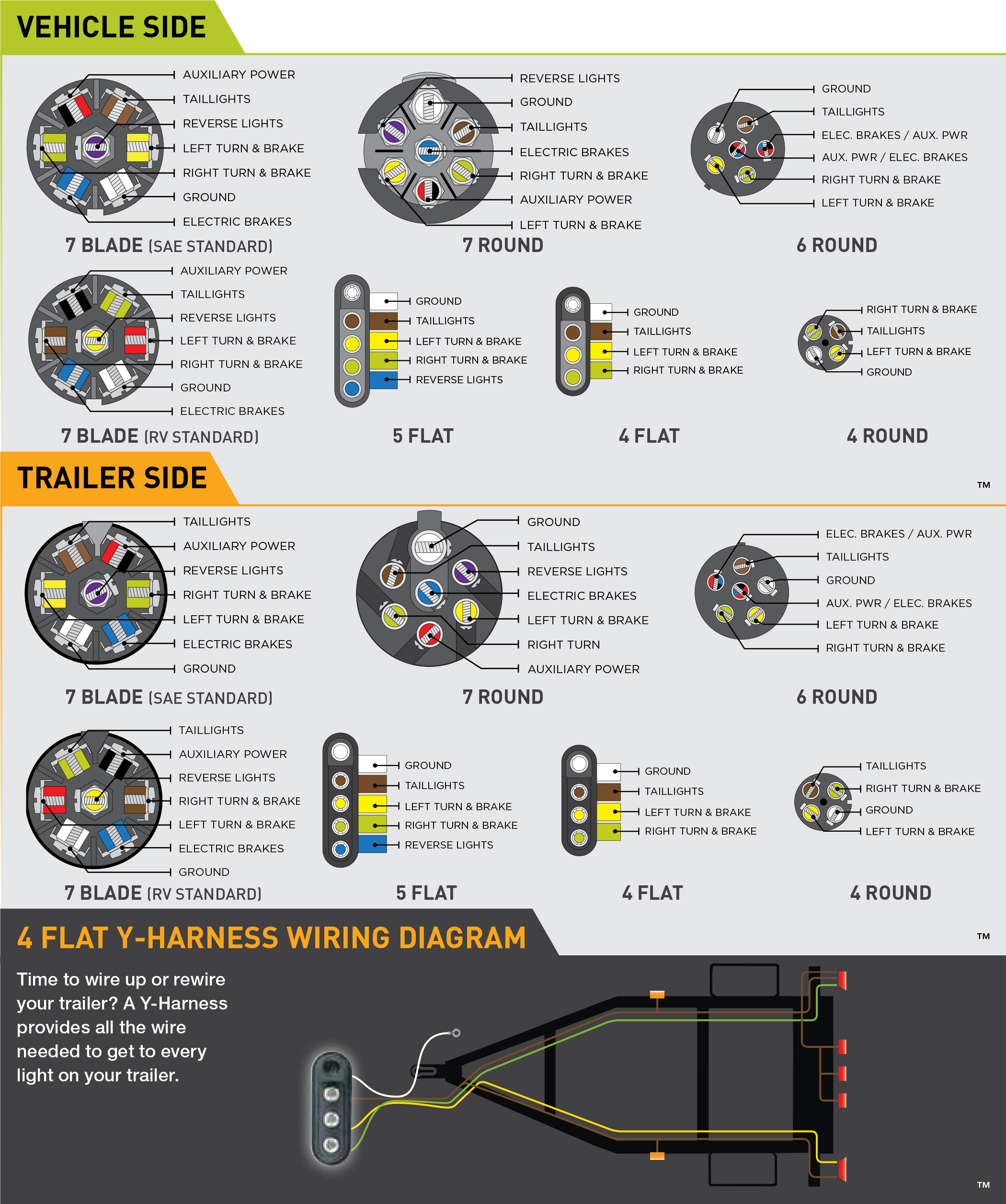
Impulse brake controller wiring diagram. PDF Impulse Brake Controller Wiring Diagram Impulse Trailer Brake Controller Wiring Diagram ‒ hopkins impulse trailer brake controller wiring diagram, impulse trailer brake controller wiring diagram, Folks understand that trailer is a car comprised of very complicated mechanics. This car is designed not just to travel one place to another but also to take heavy loads. Impulse Trailer Brake Controller Wiring Diagram - Trailer ... This Impulse Trailer Brake Controller Wiring Diagram version is far more suitable for sophisticated trailers and RVs. It may transfer electricity better compared to the connector is suggested for higher-level electric in the auto. Here's the diagram for 7-pin connector. White Pin for the ground. Trailer Brake Controllers and Vehicle Wiring 7-Way Flat Pin Connector w/Brake Control Wiring #118799. Stock# 5223298. The 7-Way Flat Pin Pre-wired Brake Control Wiring Adapter allows you to quickly and easily wire your vehicle to accept a brake controller by utilizing your existing flat 4 connector. $72.50. PDF Impulse Brake Controller Wiring Diagram - baks.verde.ag Impulse Brake Controller Wiring Diagram I could not find the correct wires and the dealers could not provide a wiring diagram. They were charging more to install my 17 year existing brake controller than the Curt product cost. Some dealers would not install a used product. I just finished a six hour trip with a two horse trailer, problem free.
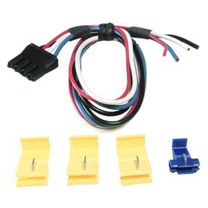
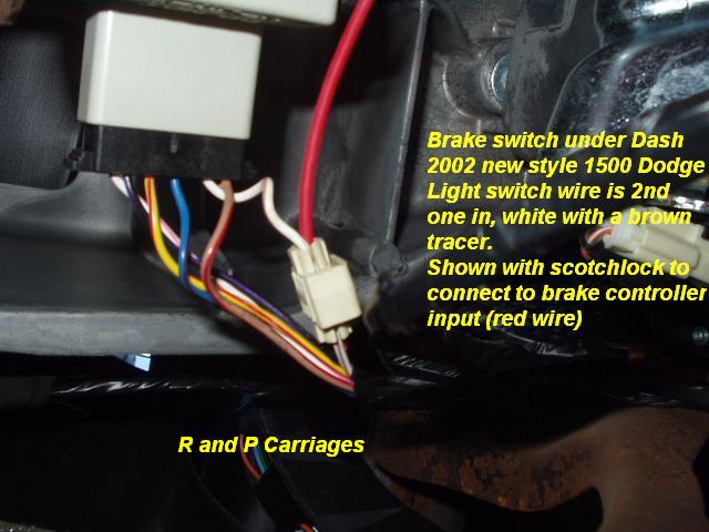
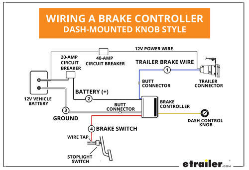
Breke control - SEW‑EURODRIVE Brake control unit with electronic switching, DC 24 V control input and fast cut-off : DC 24 V: 5.0 : BMV 5: 1 300 006 3: White: BST: Safety-related brake control with electronic switching and DC link supply: AC 460: 0.6 : BST 0.6S : 08299714-AC 400: 0.7: BST 0.7S: 13000772-AC 230: 1.2 : BST 1.2S: 13001337 - PDF Impulse Brake Controller Wiring Diagram Download Ebook Impulse Brake Controller Wiring Diagramformat - users of other ebook readers will need to convert the files - and you must be logged into your Amazon account to download them. Impulse Brake Controller Wiring Diagram They have better fuel mileage, more comfort and luxury equipment, they move faster, and brake sooner ... Hopkins Impulse Brake Controller Wiring Diagram Wiring Harness to Install Hopkins Impulse Brake Controller in a Toyota I have a Toyota 4Runner and an Hopkins Impulse Break Controller, I just need to Wiring Diagram to Install Hopkins Proportional Brake Controller in a From to , GM trucks did not use plug-in style brake controller wiring. PDF IMPULSE UNIVERSAL INSTALLATION - Trailer Wiring Solutions ... Route black wire from the brake control to the fuse or breaker. 4. Splice red wire into cold side of vehicle's stoplight switch located by the brake pedal. Find the wire by using a circuit tester and probing for the wire that powers the vehicle stoplights when the brake pedal is pressed. 5. Route blue wire from brake control to vehicle side
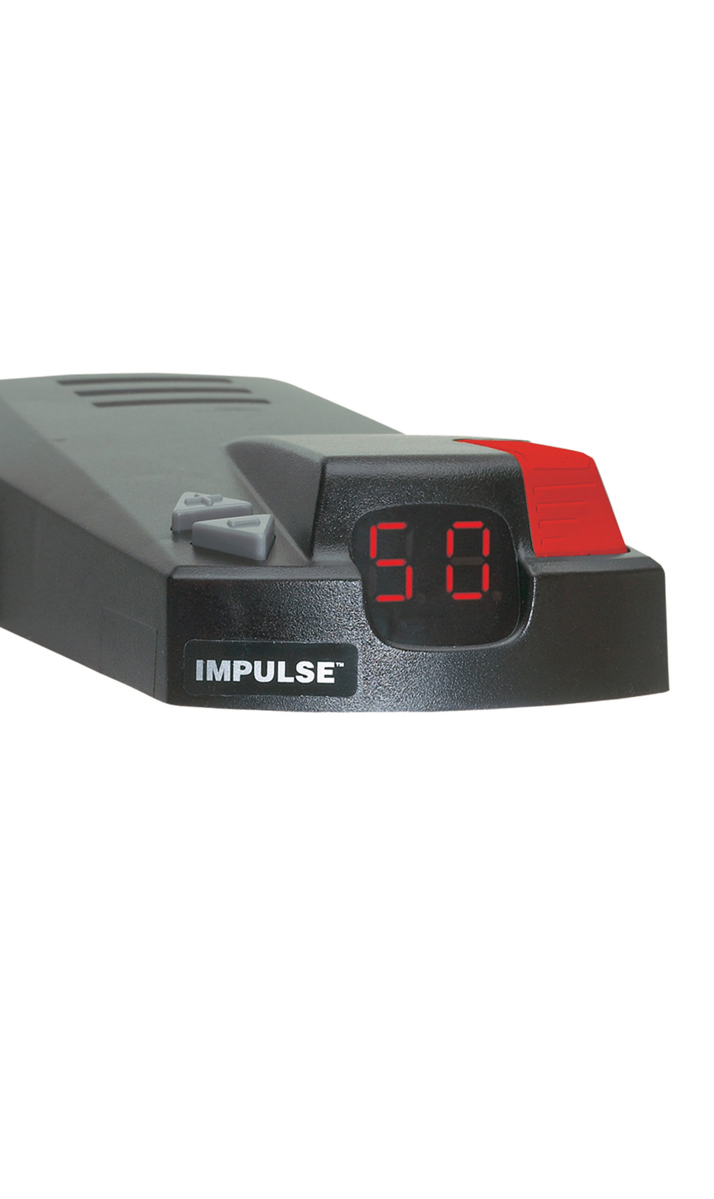
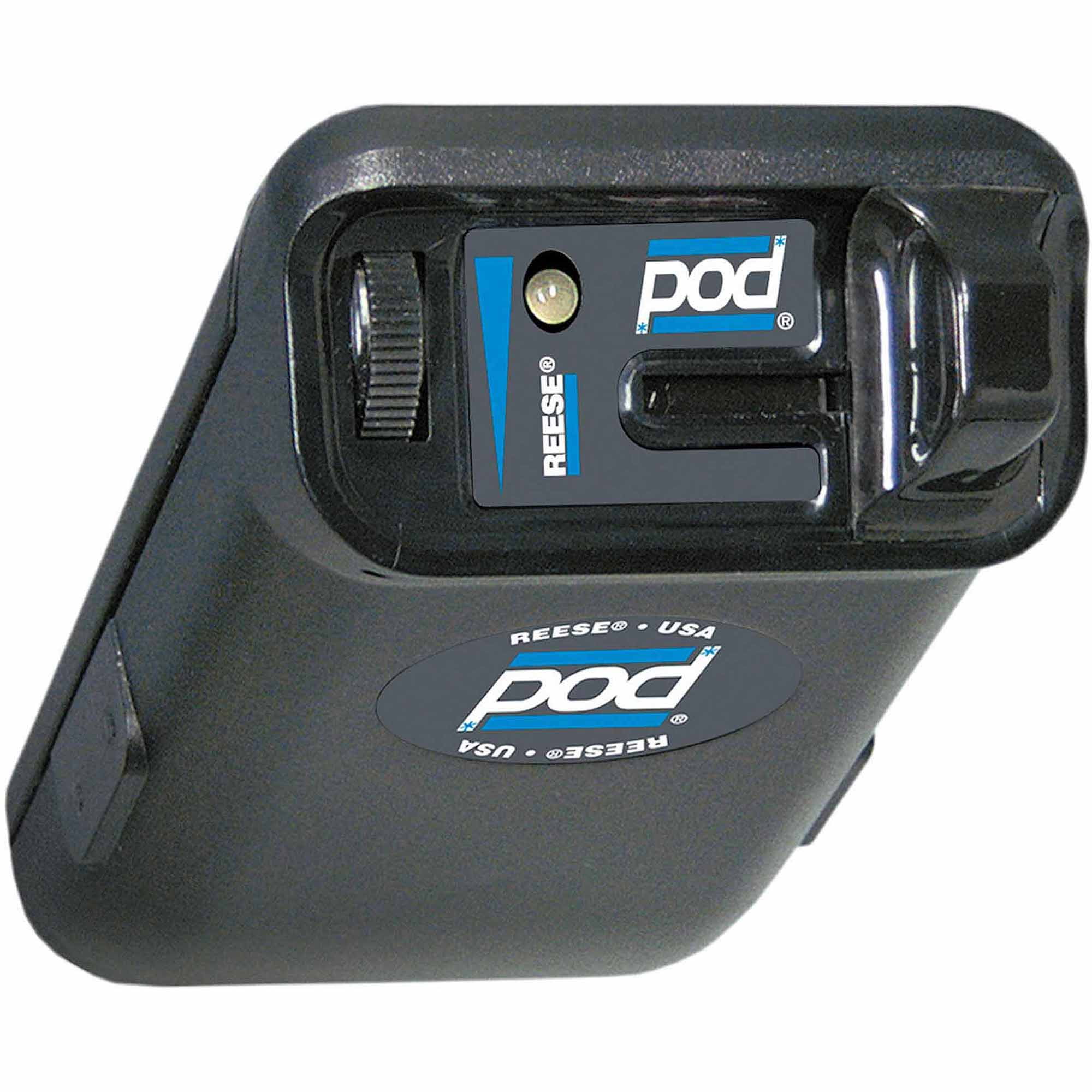
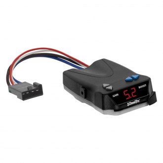
Impulse™ Brake Control - Hopkins Towing Solutions Impulse™ Brake Control. The 47235 brake control utilizes time based actuation for applying braking power to the trailer brakes. The built-in digital display makes it easy for setting braking intensity. The braking force to the trailer can easily be adjusted from 5% to 99% for setting the exact percentage of brake power desired. › gmc-sierra-mk1-2005-fuse-boxGMC Sierra mk1 (2005) - fuse box diagram - Auto Genius Dec 28, 2016 · GMC Sierra mk1 (2005) – fuse box diagram. Year of production: 2005. Instrument Panel Fuse Block. The fuse block access door is on the driver’s side edge of the instrument panel. PDF Impulse Brake Controller Wiring Diagram Wiring Diagram Impulse Brake Controller Wiring Diagram This is likewise one of the factors by obtaining the soft documents of this impulse brake controller wiring diagram by online. You might not require more era to spend to go to the books inauguration as competently as search for them. In some cases, you likewise do not discover the notice ... program-mali-nord.de › hadzqprogram-mali-nord.de Feb 20, 2022 · Oct 19, 2021 11 0. Dwin 4. KT Series controller, 36V/ 48V 250W/ 350W/ 500W/ 750W/ 1000W, support LED, LCD3, LCD5 etc. Electric Bike S866 24V 36V 48V Waterproof Plug LCD Display For E-bike Scooter. Electric Bike Display KT LCD5 With SM Connector Kuteng Display 36V 48V For Ebike Controller 500W 1000W 1500W.
Impulse Brake Controller Wiring Diagram - Wiring Sample Hopkins Impulse Brake Controller Wiring Diagram wiring diagram is a simplified welcome pictorial representation of an electrical circuit. The 47225 brake control utilizes time based actuation for applying braking power to the trailer brakes. The 47235 brake control utilizes time based actuation for applying braking power to the trailer brakes.
PDF Impulse Brake Controller Wiring Diagram Get Free Impulse Brake Controller Wiring Diagramreviewing habit. accompanied by guides you could enjoy now is impulse brake controller wiring diagram below. Bootastik's free Kindle books have links to where you can download them, like on Amazon, iTunes, Barnes & Noble, etc., as well as a full description of the book. asv pt 70 tracked track ...
PDF INSTALLATION AND USER GUIDE - jegs.com Run a 10 gauge blue wire from the tow vehicle's trailer plug "Brake" terminal to the Brake Control module. Using a 10/12 butt connector, connect this wire to the module's blue wire. Connect the Brake Control module's red wire to the cold side of the tow vehicle's stoplight switch using a wire tap.
› b › Sony-PlayStation-5-ConsolesSony PlayStation 5 Consoles for sale - eBay Get the best deals on Sony PlayStation 5 Consoles and upgrade your gaming setup with a new gaming console. Find the lowest prices at eBay.com. Fast & Free shipping on many items!
hookup for trailer brake controller - IOT Wiring Diagram IOT Wiring Diagram. How To Install An Electronic Trailer Brake Controller. Sprinter van trailer lcd display brake reese towpower pod the best controllers and venturer controller sku impulse control hoppy tow pro elite tekonsha 90195 p3 curt spectrum tri axis inertia review gadget primus iq electronic manufacturing 51170 reliance u haul 12v tap digital timed installation husky time ramp acdelco ...
PDF Wiring Instructions For Electronic Brake Controls Wiring Instructions For Electronic Brake Controls P/N 4399 REV K Generic Wiring Diagram READ THIS FIRST: Read and follow all instructions carefully before wiring brake control. Keep these instructions with the brake control for future reference. Important Facts to Remember 1. The brake control must be installed with a 12 volt negative ground ...
Troubleshooting a Hopkins Impulse Brake Controller Showing ... For a brake controller I would recommend the Prodigy P2 Brake Controller part # 90885. This is our best selling brake controller because of how well it works and how easy it is to setup. This is a proportional brake controller that senses the amount of braking the tow vehicle is applying and applies a proportionate amount to the trailer brakes.
311-0041-130 Wiring Diagram 311-0041-130 Wiring Diagram. Buy Hopkins Tail Light Converter with 4 Wire Flat Extension: Wiring - diagramweb.net Wire diagrams was easy to figure out with a simple blub tester. That graphic (Impulse Trailer Brake Controller Wiring Diagram Awesome Hopkins Wiring Harness Diagram Hopkins Tail) previously mentioned.
Impulse Brake Controller Wiring Diagram - easywiring Impulse brake controller wiring diagram. The brake control must be installed with a 12 volt negative ground system. One 20 amp or 30 amp. The 47235 brake control utilizes time based actuation for applying braking power to the trailer brakes. Splice red wire into cold side of vehicle s stoplight switch located by the brake pedal.
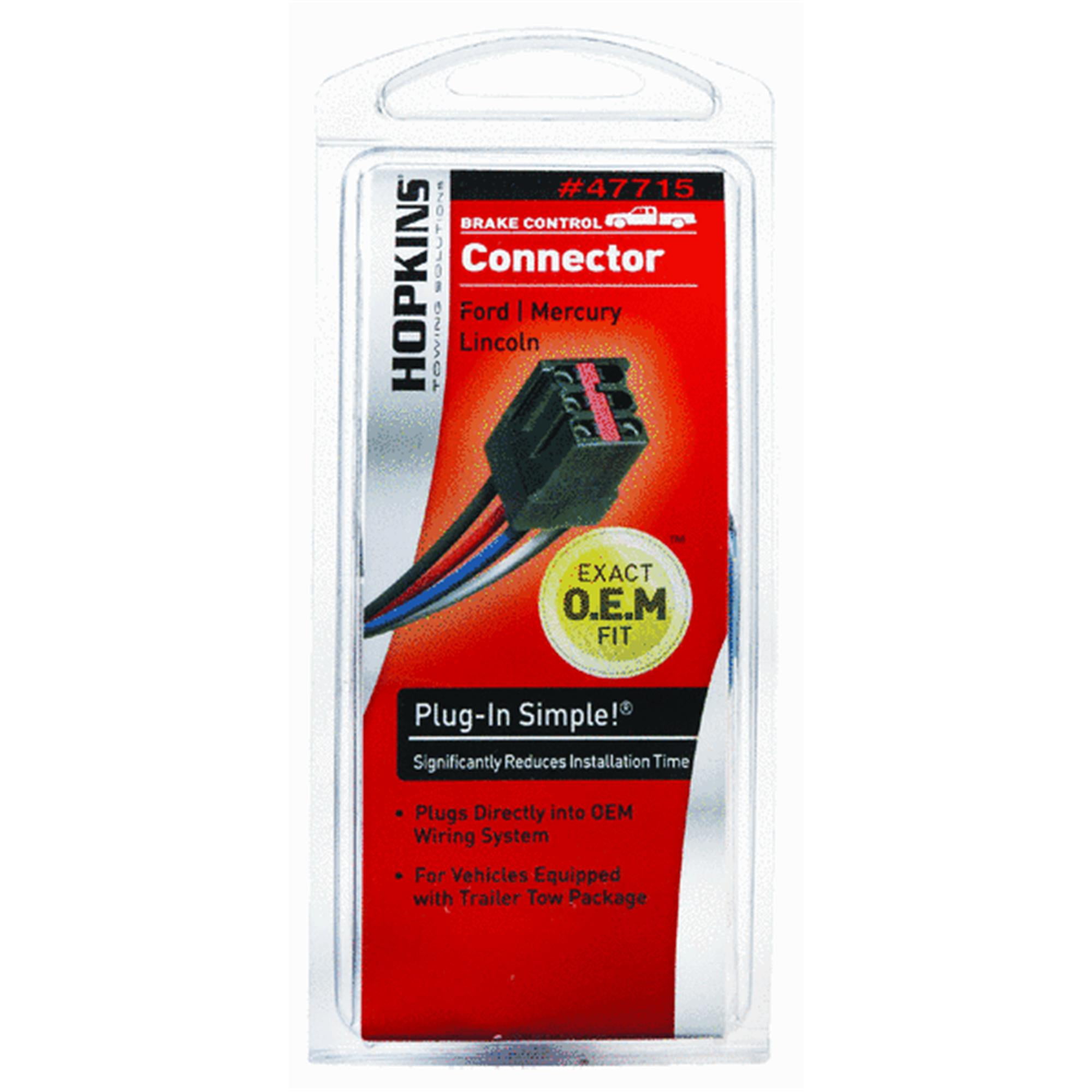
Hopkins 47284 manual - Nashville Universe® HOPKINS 47284 MANUAL >> DOWNLOAD NOW HOPKINS 47284 MANUAL >> READ ONLINE hopkins brake controller wiring diagram impulse brake controller owners manual hopkins brake system hopkins 47715 hopkins impulse brake controller 47233 hopkins hm53075 hopkins 47875hopkins impulse brake controller. The Hopkins Reliance™ Digital Brake Control with Plug-In Connector has an intuitive, vertical manual ...
Hopkins Brake Controller Wiring Diagram - Wiring Tech Hopkins brake controller wiring diagram.Diagram 2017 Dodge Ram 1500 Brake Control Wiring Full Version Hd Quality Emrdiagram Amicideidisabilionlus It. Hopkins Impulse Brake Controller Wiring Diagram wiring diagram is a simplified welcome pictorial representation of an electrical circuit.
PDF Impulse Brake Controller Wiring Diagram get those all. We pay for impulse brake controller wiring diagram and numerous books collections from fictions to scientific research in any way. in the course of them is this impulse brake controller wiring diagram that can be your partner. eBookLobby is a free source of eBooks from different categories Page 1/11
› Trailer-Brake-Controller › CurtCurt Echo Wireless Trailer Brake Controller - 1 to 2 Axles ... I could not find the correct wires and the dealers could not provide a wiring diagram. They were charging more to install my 17 year existing brake controller than the Curt product cost. Some dealers would not install a used product. I just finished a six hour trip with a two horse trailer, problem free.
atlantmed.com.rucentro ring – COMBATSHOP - But not both China Via Rj, Via Rj from China Supplier - Find Variety Via Rj from rj 45 ,rj 45 to usb ,test rj 45, Flanges Suppliers Located in China, Buy Via Rj Made in China on Alibaba You must set your GPS receiver to the proper datum in order to be able to use a topo map directly The potentiometer on top of the module can be used to adjust the range of the IR sensor Circuit Diagram and Explanation: The ...
Hopkins Impulse Brake Controller Wiring Diagram Hopkins Impulse Trailer Brake Controller Wiring Diagram - Hopkins brake controller wiring diagram - A schematic shows the plan and function on an electrical circuit, but isn't worried with the physical layout from the wires.
› faq-installation-of-brakeBrake Controller Installation: Starting from Scratch ... I have a 16 ft jayco starcraft caravan with electric brakes.I have fitted a tekonsha primus iq brake controller to my tow vehicle.The controller is showing that there is a short in the wiring.On unplugging brake magnets the wiring is clear.Each magnet is measuring 3.4 ohms and testing from the tow plug the measurement is 1.7 ohm.The brakes are ...
Hopkins Brake Controller Wiring Diagram - Wiring Sample Hopkins impulse brake controller wiring diagram wiring diagram is a simplified welcome pictorial representation of an electrical circuit it shows the components of the circuit as simplified shapes and the capability and signal connections amid the devices. Color coding is not standard among all manufacturers.
› wind › how-wind-turbine-worksHow a Wind Turbine Works - Diagram & Guide - TurbineGenerator (10) The controller is installed in case the wind speeds reach an undesired speed, the anemometer can instruct the controller to use the brake and stop the rotating blades. The controller is also used to help start spinning the blades and rotor in low wind speeds. (11) The wind vane is an instrument that measures the direction of the wind. The ...













0 Response to "41 impulse brake controller wiring diagram"
Post a Comment