42 compressed air system piping diagram
PDF Compressed Air Piping Recommendations for Compressor ... of the air compressor. The same holds true for galvanized air compressor discharge and distribution piping. Often, due to the aggressive acidic characteristics of condensate, the life of the galvanized coating may be shorter downstream of the air compressor. Copper Piping Copper pipe is a common selection for sensitive compressed air systems and Operator Manual: Atlas Copco GX5 Air compressor – Tommy Car ... 2.3 Oil system. GX Pack. GX Full-Feature. Air pressure in the oil separator tank (OT) forces the oil from the tank to compressor element (E) via oil cooler (Co) and oil filter (OF). Compressed air and oil flow into oil separator/tank (OT) where most of the oil is separated from the air by centrifugal action.
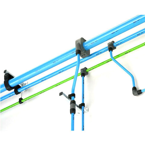
Compressed Air Piping | Air Treatment|Gardner Denver While there are many options for compressed air piping, Quick-Lock and Big-Lock aluminum compressed air piping is the ideal choice for your industrial application, including air with or without oil. Loose less air, gain corrosion resistance and more with aluminum compressed air piping from Gardner Denver.

Compressed air system piping diagram
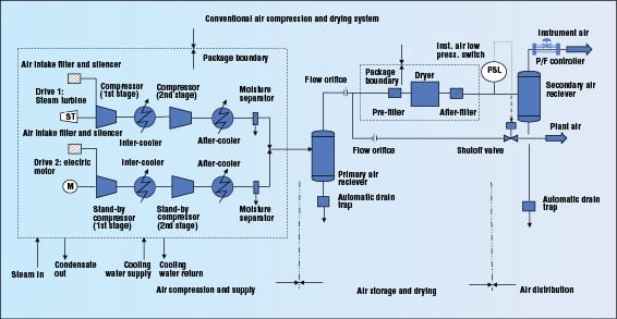
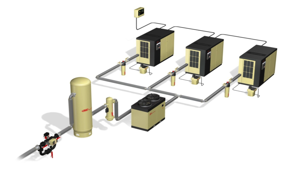
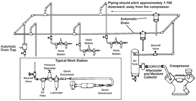
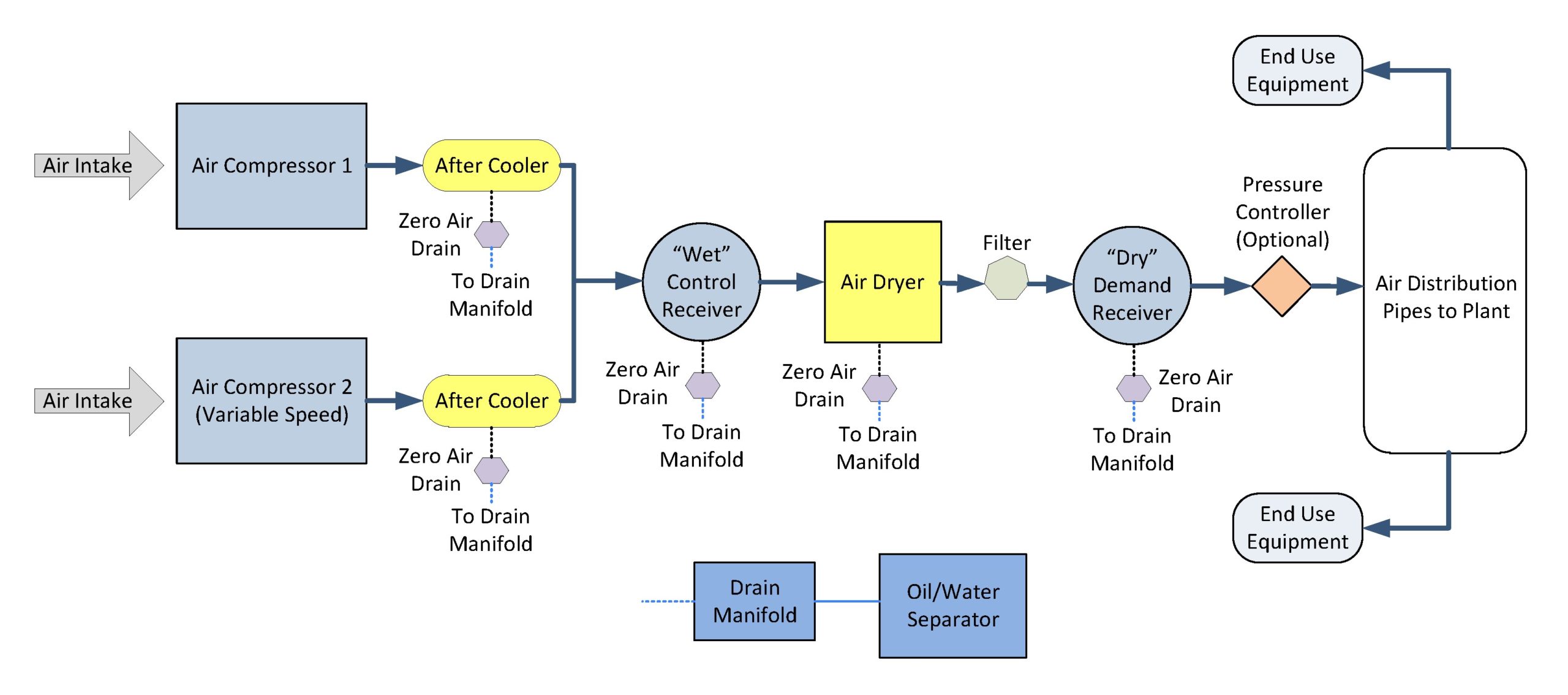
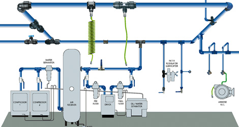
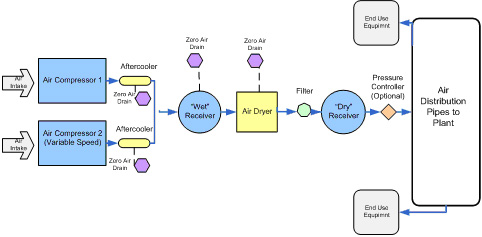
Air Compressor Installation Guide - Tips & Setup Diagram Compressed Air System Configuration. Every company's needs are unique, but when installing a compressor system, we generally recommend that systems include a wet receiver between the compressor and air dryer and a dry receiver after the dryer. The compressor should have a moisture separator. The dryer should have a pre-filter and an after filter. Air Compressor Piping Diagrams and Tips | Tools Haunt 25 Aug 2019 — An air compressor piping diagram is created by connecting an air compressor to any end-user tool through the use of a pipe. SimplAir Compressed Air Piping | Ingersoll Rand SimplAir Compressed Air Piping. The new SimplAir piping system from Ingersoll Rand uses marine-grade aluminum pipes to efficiently distribute leak-free supplies of high-flow compressed air and other inert gasses and support vacuum systems as well. For lower cost, higher performance, easier installation, and less maintenance than systems made of ...
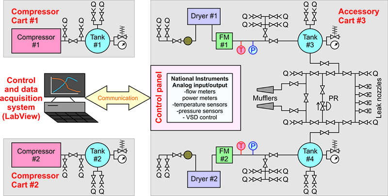
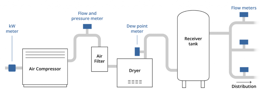
Compressed air system piping diagram. Basics of Pneumatics and Pneumatic Systems - IspatGuru Nov 14, 2015 · This compressed air is then supplied to the system through a series of pipes and valves. The word ‘Pneuma’ means air. Pneumatics is all about using compressed air to do the work. Compressed air is the air from the atmosphere which is reduced in volume by compression thus increasing its pressure. PDF Introduction INTRODUCTION TO BEST PRACTICES FOR COMPRESSED ... Best Practices for Compressed Air Systems xv SUMMARY OF KEY POINTS FROM COMPRESSED AIR CHALLENGE® TRAINING: "Fundamentals of Compressed Air Systems" and "Advanced Management of Compressed Air Systems" 1. Know what equipment you have. Develop a basic block diagram of compressors, dryers, filters, Design a Compressed Air System | Air System Builder | RapidAir Design Your Own Compressed Air Piping System. RapidAir's System Designer is a free 3D drawing tool that will help you easily create a compressed air piping system for your facility or workshop. Our drag-and-drop features give you complete control over your design. When you've completed the design, save your project by creating an account. Air Compressor Piping Diagrams and Tips - Best of Machinery When there are lots of sharp angles in an air compressor piping diagram, the following happens: The speed of air slows down The flow of air is interrupted The pressure decreases Just like when you're driving, you must decrease your speed if you need to make a sharp turn. The same applies to air in an air compressor pipe system.
PDF Various Locations, Afghanistan - United States Army all other piping systems used in the building, including sections and details, especially of congested areas, etc. d. Flow diagrams of compressed air systems including all equipment such as air compressors, accessories, pipe, tubing, and control valve actuators or any other equipment to which air is supplied. e. Air Compressor Piping Diagrams and Tips - Home Tool Guides The compressor specifications and parts suppliers usually provide a chart or manual to figure out the correct moisture content. Obstruction Destruction. I'm not sure who's worse, the obstruction that caused the break in your air piping, or the one who sold the system. As a tech in the field, it's been my experience that a broken air system is ... Compressor Inlet Piping | Compressed Air Best Practices The question of galvanized piping comes up often in compressed air system piping instead of schedule 40 black iron for the nominal 100 psig air systems. To help evaluate this, let's look at inlet and discharge piping separately. Compressed Air Purification & Piping Monthly e-Newsletter. Compressed Air Piping (Considerations Before Buying) THE PIPING SYSTEM AND COMPRESSED AIR. An air compressor is a device that transfers power using an electrical, diesel, or gasoline engine, in the form of compressed air. Piping systems bring together every element of your compressed air system and can make or break a system.
Air Piping Layout - Sharpe Manufacturing Shop Air Piping Layout Diagrams. As we all know, compressed air is a key element in everything we do in the shop. And the quality of the paint job on ... Modeling of Industrial Air Compressor System Energy ... Fig. 1.1. Typical Lifetime Compressed Air Costs [2]. 1.2 System Diagram Figure 1.2 shows a typical air compressor system diagram. The fresh air intake ows into a lter before entering the compressor. Many of the industrial air com-pressors come in a closure that will include multiple components such as compressor, motor, aftercooler and a separator. Compressed Air System Schematic Diagram - SYAHME1410 Figure 2 From Optimization Of Compressed Air Storage S . Volvo Service Bulletin 5 56 51 . Mellcon Hoc 7kg Cm2 100psi An Ideal Compressed Air System . Machinery Resale Offers Used Construction Equipment Solutions . A C Piping Diagram Shop Air Piping Layout Diagrams . A Hybrid Energy Storage System Using Pump Compressed Air And PDF 3. COMPRESSED AIR SYSTEM - Bureau of Energy Efficiency 3.4 Compressed Air System Components Compressed air systems consist of following major components: Intake air filters, inter-stage coolers, after coolers, air dryers, moisture drain traps, receivers, piping network, filters, regula-tors and lubricators (see Figure 3.6).
Item # CGK-3-4, 3-4 Bay Compressed Air Piping Kit On ...
Premium Compressed Air Piping, pipes for compressed air ... RapidAir is the leader in affordable compressed air piping systems. Whether you are looking for commercial, industrial options, or are installing your first compressed air system for a client or your own garage, we make it easy to get exactly what you need, when you need it. When you need a part, you can count on us having it in stock.
By Hank van Ormer, Air Power USA SUSTAINABLE MANUFACTURING ...
Water Supply Fixture Units - WSFU vs. GPM and Liters/sec Sanitary Piping - Drainage Fixtures Unit Loads - Maximum Drainage Fixture Unit - DFU - loads in sanitary piping systems. Water Supply - Calculating Demand - Calculating expected demand for water supply service lines. Water Supply Fixture Units WSFU - WSFU is used to calculate water supply service systems.

Improving Compressed Air System Efficiency: Part 4 | Power ...
Air Compressor Piping Diagrams And Tips | iPower Toolz Various aspects need to be taken under consideration while creating an air compressor piping diagram. Like for instance moisture, or any snag, layout, etc. In my perspective piping is the deal-breaker, as it can either make your business or break it. A fault in the pipeline means loss of power, which in other words means more unnecessary expenses.
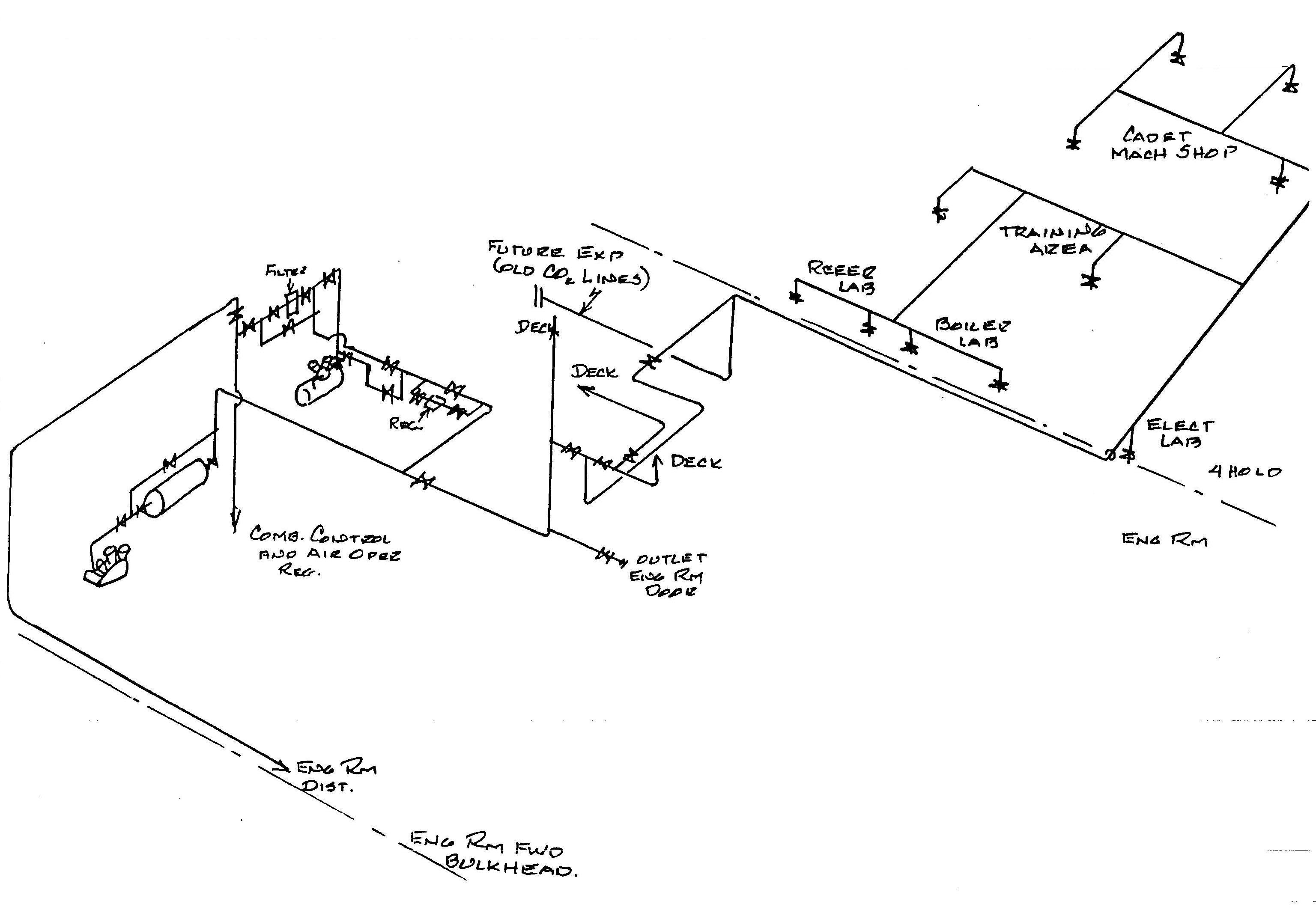
USS Holland 50 PSI Compressed Air System
SYSTEM DESIGN PROCESS PLANT PIPING OVERVIEW OF Piping System Corrosion General or Uniform Corrosion Uniform metal loss. May be combined with erosion if high-velocity fluids, or moving fluids containing abrasives. Pitting Corrosion Localized metal loss randomly located on material surface. Occurs most often in stagnant areas or areas of low-flow velocity. Galvanic Corrosion

The Best Air Compressor Pipe for Your Air Compressor ...
Compressed Air Basics - Piping - Air Compressor Works, Inc. Compressed Air Basics - Piping. February 23, 2018. Your air compressor is the heart of your air system. Most customers focus on the compressor and consider the piping as a secondary concern. However, just like a heart can fail because of clogged arteries, a compressor can fail because of improper piping. You have many different options on the ...
Compressed Air Piping
Calculating Compressed Air Pipe Size | Quincy Compressor Compressed Air Pipe Sizing. A mistake that some users make is to simply assume that energy lost due to over-pressurization is merely collateral for the occasional high-pressure application. Fact is, this is the performance and longevity of your compressed air system at stake.
TSPS Engineering Manual
Compressed Air Piping - Pressure Loss Diagrams, Imperial Units Download and print Compressed Air - Pipe Line Pressure Drop (gauge Pressure 50 psig) Compressed air pipe line pressure loss diagrams - metric units. 1 ft (foot) = 0.3048 m. 1 cfm = 1.7 m3/h = 0.028 m3/min. 1 psi = 0.069 bar = 0.070 kg/cm2.

QLK32 Air Cooling Piping System 1/2"
Air Compressor Piping Diagrams and Tips From Experts General Rules of Air Compressor Piping Diagrams. Piping is a very important component when it comes to designing and developing a successful air compressor system. As compressed air faces a risk of losing pressure across the system (pressure drop), or even contamination along its path.
Compressed Air Piping Changes Help Dairy Producer Optimize ...
PDF Distribution PiPing - Compressed Air Challenge Best Practices and Tips for Compressed Air Piping Systems A brief synopsis of "Section 3, Distribution System" from Best Practices for Compressed Air Systems follows. This 325-page book is available at our bookstore. Pressure losses due to inadequate piping will result in increased energy costs and variations
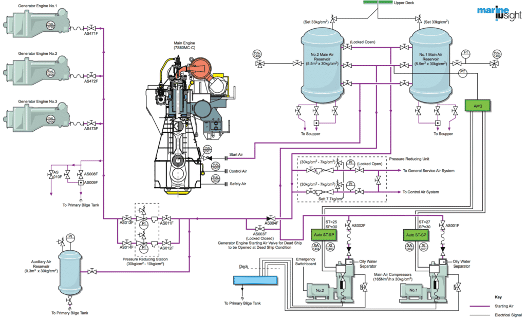
Compressed Air Line On Ships - A General Overview
QT and QTS Series Compressors - Air Energy Jun 30, 2003 · cooled in downstream air piping. Compressed air dryers reduce the moisture vapor concentration and prevent water formation in compressed air lines. Dryers are a recommended companion to filters, aftercoolers, and automatic drains for improving the productivity of compressed air systems.
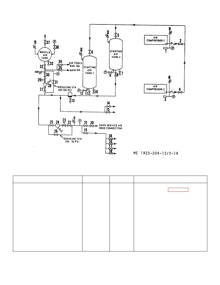
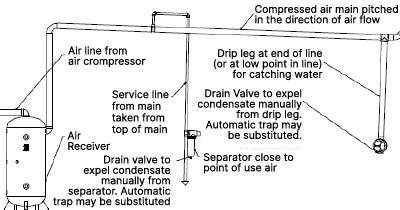
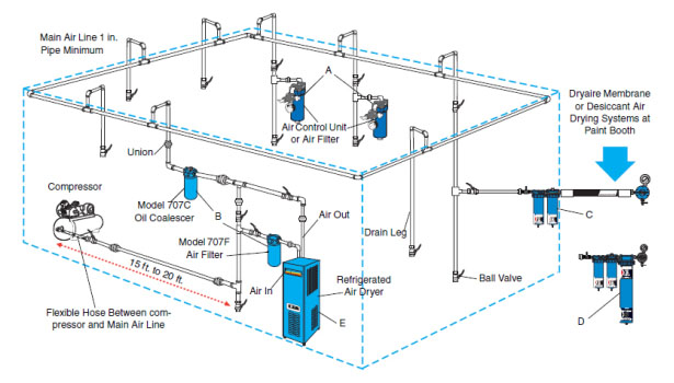
Figure 2-14. Compressed air system piping diagram.
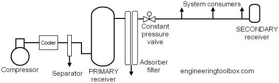
Connecting Two Air Tanks Together - About Air Compressors.com Feb 04, 2019 · This is a very important feature of any compressed air system, and is why the secondary tank is installed after the primary. This way the air from both tanks cannot escape back up the supply line when the compressor is stopped and escape through the unloader valve which is opened to atmosphere.
![Shop Air Compressor System Design & Plumbing [Complete Guide]](https://cnccookbook.com/wp-content/uploads/2021/07/AirSchematic.jpg)
Shop Air Compressor System Design & Plumbing [Complete Guide]
Compressed Air Piping - Emax Compressor Rapid Air 3/4″ Maxline Compressed Air Piping System Master Kit. Silent Air Technology. QUICK LINKS. Rotary Screw Air Compressors Piston Air Compressors Air Compressor Pumps Compressed Air Dryers Air Compressor Tools Air Compressor Parts & Accessories. RESOURCES. Find Service Warranty Plans Manuals
Design and Specification of A Compressed Air System ...
Air Piping Layout - Sharpe Manufacturing Air Piping Layout Shop Air Piping Layout Diagrams . As we all know, compressed air is a key element in everything we do in the shop. And the quality of the paint job on refinishing work is affected by the quality of the compressed air we use. The quality of our compressed air is also effected by how our air delivery lines are laid out in our shops.

Hospital Air Compressors-Introduction of Hospital Compressed ...
Designing Your Compressed Air System - KAESER Your compressed air distribution piping is your means for transporting compressed air and represents your link between supply, storage, and demand. The ideal distribution system provides a sufficient supply of compressed air at the required pressure to all locations Sigma Air Manager Kaeser's Sigma Air Manager is the ultimate in compressed ...

Piping Systems - Library Pages
PDF How to know what size piping your Compressed Air System needs the overall air system. Steps to figuring what size piping your compressed air system needs: 1. Determine your air compressor's maximum CFM. 2. Draw a piping schematic and show all pipe fittings, valves, etc. 3. Measure and write the corresponding lengths of pipe on your schematic, then total the length of all straight pipes needed and note ...

7: Piping and instrumentation diagram (inside compressor ...
Drawing Tools HVAC Diagram - Online Drawing Tool . Draw HVAC diagrams online with this Google Drive drawing tool. Mapping Scale vs. Length and Area . Convert between mapping scales. P&ID - Piping and Instrumentation Diagram . Schematic illustration of a functional relationship between piping, instrumentation and system components. P&ID Diagram - Online ...

Qualification and Continuous Validation of a Compressed Air ...
PDF Compressed Air System Standard Piping Diagram Compressed Air System Standard Piping Diagram Author: Department of Veterans Affairs, Office of Acquisition Logistics and Construction, Office of Construction and Facilities Management, Office of Facilities Planning, Facilities Standards Service Subject: Standard Detail Created Date: 10/26/2017 1:02:30 PM
Compressed Air Receivers
Air compressor piping diagrams and tips | Learn from the ... General Rules for air compressor piping system — Read and properly understand the piping requirements of your system before installation.

Compressed Air Systems Manufacturers — Process & Power
PDF Drawing, M-015D, Rev. 21, 'Piping & Instrument Diagram ... systems shown on this drawing: 11: compressed air & gas davis-besse nuclear power station unit no. i edison piping and instrumentation diagram station air system 26 temp. sta. to service sta, no. 030-10 sa223 instr. sa203 35 air sys. servj cË sta. no. 30 sa2t8 to moisture separator f95 (h-7) 1/2 87 service sta, nc, -10 service sta. no, sa21 ...
Compressed Air - Engineering and Engineering Technology ...
Guide to Compressed Air Piping Systems | Quincy Compressor Posted on: May 15, 2020 Owners of compressed air piping systems tend to focus on the compressor and think of the piping as less of a concern. However, just as hearts can fail due to clogged arteries, compressors can fail due to poor piping. And even if it doesn't fail outright, power lost to faulty or inefficient pipes can cut into your profits.
Air Compressor Installations
Compressed Air Piping Distribution Systems Perhaps your facility recently had a compressed air system survey, conducted by an air systems services company, that resulted in a couple of major recommendations, such as: Install a new smaller compressor and new control systems on all of the units Repair the many air leaks (identified as 30% of your system capacity) These capital-intensive recommendations could involve significant process ...
MAINTENANCE - WESPRO POWER TOOLS Online - Air Tools, Electric ...
SimplAir Compressed Air Piping | Ingersoll Rand SimplAir Compressed Air Piping. The new SimplAir piping system from Ingersoll Rand uses marine-grade aluminum pipes to efficiently distribute leak-free supplies of high-flow compressed air and other inert gasses and support vacuum systems as well. For lower cost, higher performance, easier installation, and less maintenance than systems made of ...

Air Piping Layout | Air compressor, Plumbing layout, Shop ...
Air Compressor Piping Diagrams and Tips | Tools Haunt 25 Aug 2019 — An air compressor piping diagram is created by connecting an air compressor to any end-user tool through the use of a pipe.

Turnkey Installations - Rastgar Air Compressors
Air Compressor Installation Guide - Tips & Setup Diagram Compressed Air System Configuration. Every company's needs are unique, but when installing a compressor system, we generally recommend that systems include a wet receiver between the compressor and air dryer and a dry receiver after the dryer. The compressor should have a moisture separator. The dryer should have a pre-filter and an after filter.
Use Demand Storage for an Efficient Compressed Air System ...
A Simple Explanation of What Compressed Air Is - Air ...

Compressed Air
Compressed Air System Piping - Manufacturer,Supplier,Exporter ...

Air compressor piping diagrams and tips | Learn from the expert

Premium Compressed Air Piping, pipes for compressed air ...

Condensate management 101
Nonresidential Pipe Sizing and Leak Testing for Compressed ...

Compressed Air - Acker & Associates
Introduction to Compressed Air Systems

Compressed Air Systems (Energy Engineering)

RapidAir MaxLine 3/4in. 100ft. Master Kit Compressed Air Piping System, Model# M7500

Aluminum Piping System/Pneumatics/Air compressor accessories ...

2: Pipe and instrumentation (inside compressor cabinet ...

Description of compressed air and pneumatic control systems ...

Powder Coating: The Complete Guide: Plumbing Your Air Compressor

Compressed air efficiency: Don't stop at the compressor
The Importance of Clean, Dry Compressed Air for Air Plasma ...
0 Response to "42 compressed air system piping diagram"
Post a Comment