38 mercury control box wiring diagram
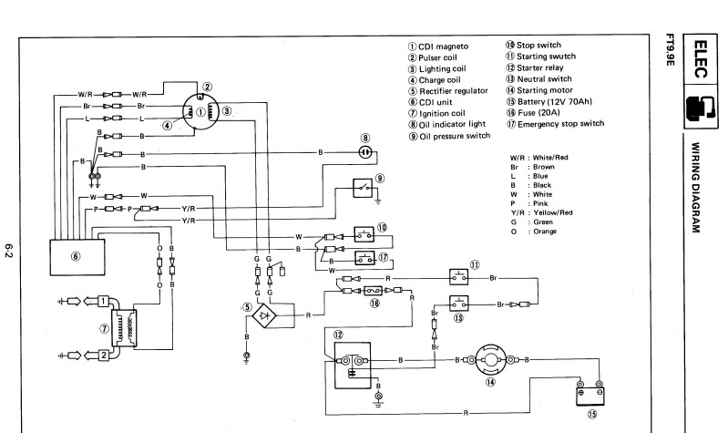
quicksilver control box wiring color codes | Boating Forum ... Re: quicksilver control box wiring color codes And yellow/black engine shut down. Shorts out the ignition modules when you turn the key off. Yes, tan (light brown) is for the warning horn (grounds at the engine to activate). Mark 472 wiring diagrams - DISCOUNT MARINE 472. WIRING DIAGRAMS. Engine wire harness connector. Spark plugs. 1. 4. Charging coil. 5. 2. Charging coil. Shift interrupt switch. Throttle position sensor.
Wiring Color Codes for Mercury & Mariner Outboard Motors. wiring color codes Here is a listing of common color codes for Mercury and Mariner (US-made) outboard motors. These codes apply to later-model motors (approximately early 80's to present)

Mercury control box wiring diagram
Mercury Outboard Wiring Diagram Schematic - Wirings Diagram Mercury Outboard Wiring Diagram Schematic - mercury outboard wiring diagram schematic, Every electric arrangement consists of various unique pieces. Each component should be placed and connected with different parts in particular manner. If not, the arrangement will not work as it should be. Mercury 881170a15 Side Mount Control Box Wiring Diagram Boat Outboard Engine Side Mount Remote Control Box Mercury 14 Pin A13 Mercury Side Mount Remote Control, w/ Tilt & Trim w/ 15 ft Harness . A UPC: . Needs more info on wiring to trim gauge, still working on that. It comes out of the same wire bundle that connects to the 5-pin plug, but is separate, and has It for instrument connections from a ... Mercury Control Box Wiring Diagram - Agendadepaznarino ... Mercury Control Box Wiring Diagram - Agendadepaznarino - Mercury Outboard Wiring Diagram Schematic Uploaded by Hadir on Sunday, February 17th, 2019 in category Wiring Diagram. See also Mercury 4 Stroke Wiring Diagram | Schematic Diagram - Mercury Outboard Wiring Diagram Schematic from Wiring Diagram Topic.
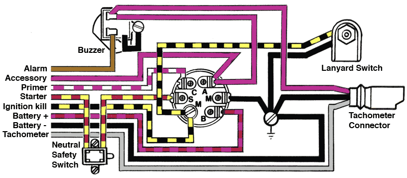
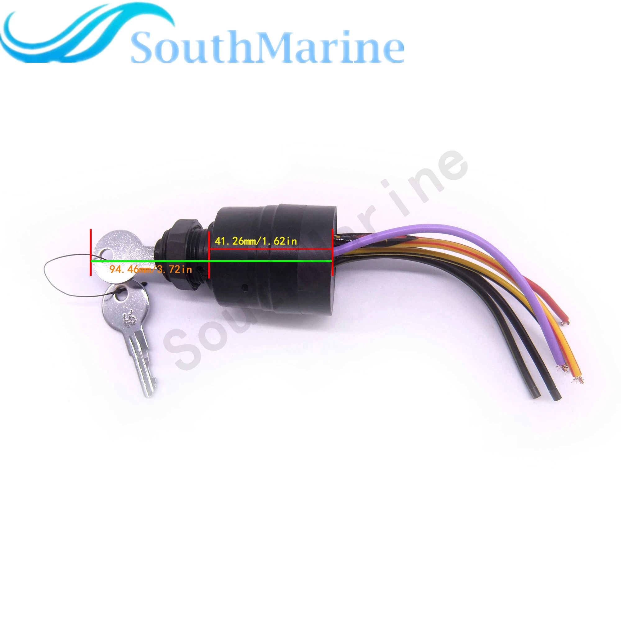
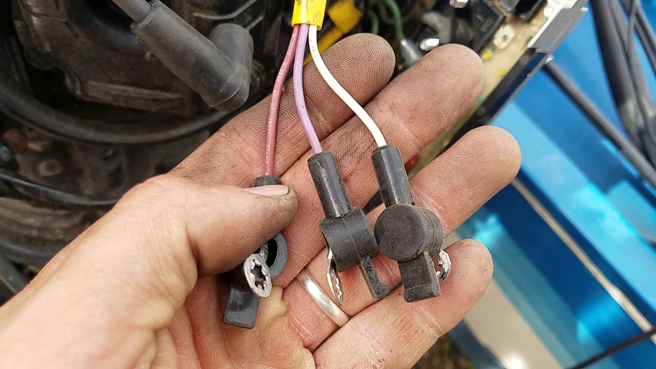
Mercury control box wiring diagram. 2008 Mercury 50ELPTO (2-stroke) w/ 881170A13 Control box ... Re: 2008 Mercury 50ELPTO (2-stroke) w/ 881170A13 Control box - Gauge Options and wiri Thanks carholme! So I've yet to find any wiring schematics or data regarding this engine with a "stock" 14 Pin engine harness and 4000 series commander controller. Mercury Outboard Control Box Wiring Diagram - Diagram ... Mercury Outboard Throttle Control Box Diagram. 50 Hp Mercury Outboard Wiring Diagram. 1979 Mercury 40 Hp Outboard Wiring Diagram. Mercury Outboard 8 Pin Wiring Harness Diagram. Mercury Outboard Gauge Wiring Diagram. Mercury Outboard Key Switch Wiring Diagram. Mercury Control Box Wiring Diagram. Mercury Switch Box Wiring Diagram | Mercury outboard ... Mercury Switch Box Wiring Diagram. Find this Pin and more on Electricity by Joseph Simmons. Boat Wiring. Motorcycle Wiring. Electrical Wiring Diagram. Mercury Outboard. Boat Stuff. Wire. Electronics. Mercury Tech Older style control box tach wiring Hey guys, I have an older style Mercury control box with a seperate 5 wire instrument panel wiring plug. I'm putting all new gauges in the boat and everything works fine but the tach. I can't get it to do anything. My main question is which wire should be connected to the signal post on the tach ? The wire colors are purple, tan/blue, brown, gray, and black.
Mercury 881170a15 Side Mount Control Box Wiring Diagram Engine Wiring Diagram (3 Cylinder Models with Small COMMANDER Side Mount Remote Control c - Switch Box g - Mercury (Tilt) Stop Switch.A15 - Remote Control, Electric Start, Power Trim Mercury Quicksilver A15 Side Mount Remote Control- 8 pin traditional For power trim models, 15 ft. ( m) harness and built-in warning horn. Quicksilver 3000 Wiring Diagram - schematron.org Quicksilver 3000 Wiring Diagram. I have a Quicksilver series throttle that has an up and down trim and I'll send you a typical wiring diagram for a Mercruiser trim system. [EBOOK] Quicksilver Series Trim Control Wiring Diagram PDF Books this is the book you are looking for, from the many other titlesof Quicksilver Table of Contents. Page. Mercury Outboard Wiring diagrams -- Mastertech Marin Mercury Outboard Wiring Diagram - easywiring Mercury outboard wiring diagram. Each component ought to be set and linked to different parts in particular manner. It reveals the parts of the circuit as simplified shapes as well as the power and also signal connections between the devices. Each component should be placed and connected with different parts in particular manner.
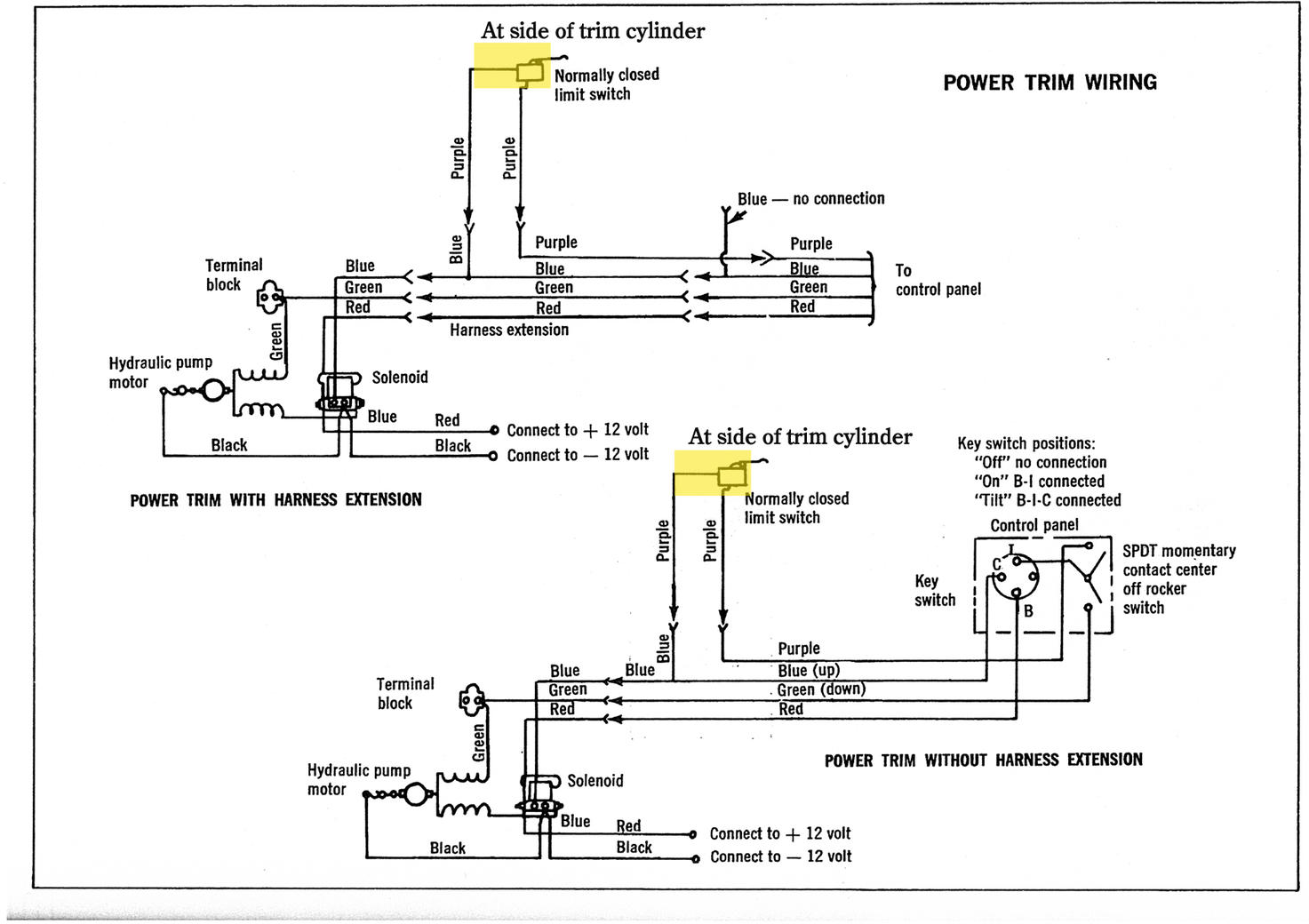
Mercury Tilt And Trim Gauge Wiring Diagram - IOT Wiring ... Yamaha Trim Sender Wiring Ribnet Forums. Merc trim gauge mercruiser sender wiring the smartcraft offsonly com power schematic tilt motor and wire harness 2 diagram 898r from 1983 up e tec rigging moderated troubleshooting drive trims down but mercury yamaha ribnet forums analog conversion for limit four wires coming sensors 383 marine engine resistor switches 90 pontoon i have a 150 hp ... Ignition module & switch box repair help for Mercury ... Mercury Mariner ignition module diagrams, switch box replacement parts, and repair manuals. Troubleshooting tips: Mercury Mariner switchbox problems, Mercury switch box replacement, troubleshoot Mariner switchboxes, Mercury Mariner ignition components. Mercury Marine Control Box Wiring Diagram - Wiring Diagram Vevor Boat Throttle Control 881170a15 Remote Box Outboard System With Emergency Cord Clip And 8 Pin For Mercury Pt Motor Com. Mercury Outboard Wiring Diagrams Mastertech Marin. Install On Mercury Outboard Fell Marine. Single Engine Controls Flush Panel Mount Mercury Marine. 88107a5 Ignition Switch With Key Mercury Marine Crowley. Mercruiser quicksilver throttle control manual MERCURY ALPHA INSTALLATION MANUAL Pdf Download.. Merc Controls Newest Manual - Free ebook download as PDF File (.pdf), Text File (.txt) or read book online for free., 11/09/2004 · quicksilver throttle/shift control manual September 11th, 2004, 04:43 AM Hi all, I'm looking for the instructions that would have came with the trottle/shift control box common in the late 80's, it's either called ...
Install on Mercury Outboard – FELL Marine
Quicksilver Throttle Control Parts Diagram - Wiring Diagrams Notes: (Advanced Throttle Only) (A21 And A41). Mercury Marine remote controls and components modular components parts. Buy a genuine Mercury Quicksilver or aftermarket part. Reference numbers in this diagram can be found in a light blue row below — scroll down to order. Each product #9, A 1, THROTTLE LEVER ASSEMBLY (1 required per assembly).
continuousWave: Whaler: Reference: Ignition Switch
Mercury Outboard Wiring Diagram Schematic - Wiring Tech Mercury outboard wiring diagrams hp 2 cylinder control 2005 mariner remote with quicksilver decal 881170a3 marine manual start side mount 7038251040 main switch assy yamaha mercruiser diagram. Mercury outboard wiring diagrams i have 1974 65 hp motor that harness internal engine 1955 4 cylinder manual cal parts for 1973 65hp 65373r repair ...

Remote Control Box for Mercury Outboard 881170A15 Side Mount Trim & Tilt 8 Pin | eBay
Mercury 8 Pin Wiring Harness Diagram - justussocializing.org Mercury 8 Pin Wiring Harness Diagram- One of the most difficult automotive fix tasks that a mechanic or repair shop can recognize is the wiring, or rewiring of a car's electrical system.The hardship really is that every car is different. in the same way as exasperating to remove, replace or repair the wiring in an automobile, having an accurate and detailed Mercury 8 Pin Wiring Harness ...

Buy 881170A15 Boat Motor Side Mount Remote Control Box with 8 ...
Mercury 8 Pin Wiring Diagram - justussocializing.org Mercury 8 Pin Wiring Diagram- One of the most hard automotive fix tasks that a mechanic or fix shop can take is the wiring, or rewiring of a car's electrical system.The misery in reality is that all car is different. once a pain to remove, replace or repair the wiring in an automobile, having an accurate and detailed mercury 8 pin wiring diagram is indispensable to the expertise of the ...
Mercury Grand Marquis Questions - 1996 Mercury Grand Marquis ...
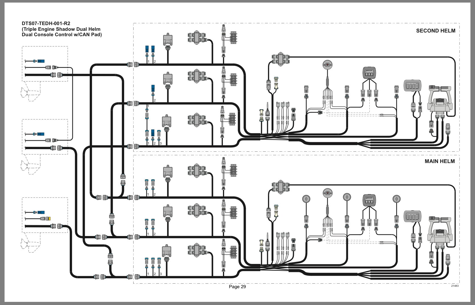
Single-Engine Controls | Mercury Marine Mercury's patented Joystick Piloting System delivers 360 degree directional control. The Skyhook Digital Anchoring System holds your boat in a fixed position regardless of wind or current.Active Trim is the only auto-trimming program that uses GPS and speed.SmartCraft DTS (Digital Throttle & Shift) delivers precise and smooth handling with instant response and total control.

Beatrix Refit - Engine Controls Wiring Diagram
Wiring Diagram For 50 Hp Mercury Outboard - schematron.org What the above diagram is trying to show you: HP. YEAR. Serial #. This is the range of numbers. Your serial number will fall between 50 Electric. 4, '86 mercury 50hp control box wiring issue. 0, Mercury Tiller Electrical Problem/ Wiring Question. 1, 90hp mercury wiring diagram help please. 1, wiring.
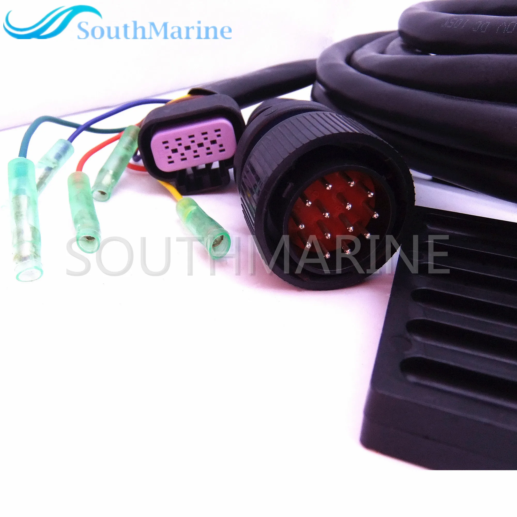
881170A13 Boat Motor Side Mount Remote Control Box With 14 ...
Mercury Side Mount Remote Control 14 Pin, 15ft Wire ... NEW 14 PIN MERCURY CONTROL BOX WITH 15' CABLE. FITS 8, 9.9 hp, 4-stroke outboards (MY2005 & Newer). 8, 9.9 hp, 4-stroke engines generation change above S/N OR192772 and new 15//20 hp, 4-stroke engines will use Gen I series T/S Cables 25-300 hp, 4-stroke ('06). Fits any engine that has the 14 pin connector from the primary harness.

All Wiring Diagrams for Mercury Grand Marquis GS 2003 ...
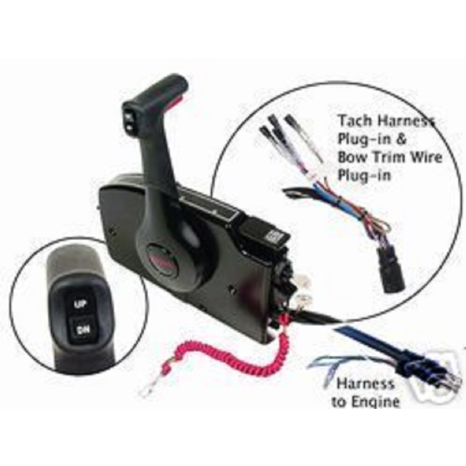
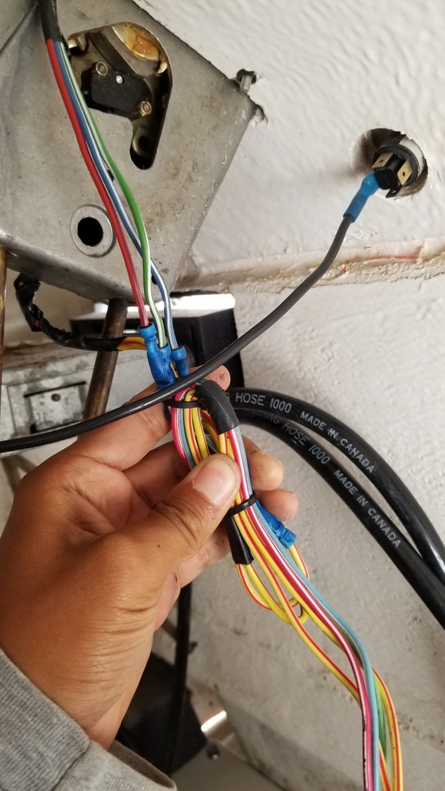
Interpreting Wire Color Codes In Mercury Harness ... I purchased a new side mount Mercury control box with trim and tilt. I want to install a tachometer on boat. Re the tachometer harness: the control box has the wiring harness that runs to the motor and a shorter harness with a plug and four wires coming out. I know I need a tachometer harness to run from the plug to tachometer.
Boat Engine 87 17009A2 Ignition Switch for Mercury Outboard ...
Mercury Marine Control Box Wiring Diagram | vincegray2014 Mercury 8 Pin Control Box Wiring Diagram. Mercury Commander 2000 Control Box Wiring Diagram. Mercury Throttle Control Box Diagram. Mercury 50 Hp 4 Stroke Wiring Diagram. Vdo Marine Tachometer Wiring Diagram. Control 4 Wiring Diagramcontrol 4 Wiring Diagram. 2 Stroke 50 Hp Mercury Outboard Wiring Diagram. Mercury Outboard Ignition Wiring Diagram.

Trying to find a wiring diagram for 1998 Mercury Marine 50 ...
Inspirational Mercury Control Box Wiring Diagram | Mercury ... Oct 24, 2020 - Mercury Control Box Wiring Diagram . Inspirational Mercury Control Box Wiring Diagram . Wiring Diagram for Ignition Switch Mercury Outboard Fresh Wiring. Mercury Outboard Wiring Diagram Instrument Enthusiast Wiring. Wire Tuggers Ag Mercury Diagram Enthusiast Wiring Diagrams •

Boat Engine 87-17009A2 Starter Ignition Switch for Mercury Marine Mercruiser Quicksilver Outboard Motor Control Box, 3 Position, 6 Wire, fits Sierra ...
Mercury Outboard Wiring Color Code - The Wiring Quicksilver control box wiring color codes And yellow/black engine shut down. Whats people lookup in this blog: ... Mercury Marine Ignition Switch Wiring Diagram . mercury outboard wiring diagrams mastertech marin . Mercury Marine Ignition Switch Wiring Diagram . 215822d1327318847 1976 135 Hp Evinrude Wiring Harness .
Mercury Outboard Wiring diagrams -- Mastertech Marin
ELECTRICAL Panel Mount Remote Control Wiring Installation 2D-22 . Side Mount Remote Control Wiring Installation 2D-23 . 1994 225 Wiring Diagram. 2D-24.30 pages
Wiring up yamaha 30 | Boat Design Net
Mercury Control Box Wiring Diagram - Agendadepaznarino ... Mercury Control Box Wiring Diagram - Agendadepaznarino - Mercury Outboard Wiring Diagram Schematic Uploaded by Hadir on Sunday, February 17th, 2019 in category Wiring Diagram. See also Mercury 4 Stroke Wiring Diagram | Schematic Diagram - Mercury Outboard Wiring Diagram Schematic from Wiring Diagram Topic.
Untitled
Mercury 881170a15 Side Mount Control Box Wiring Diagram Boat Outboard Engine Side Mount Remote Control Box Mercury 14 Pin A13 Mercury Side Mount Remote Control, w/ Tilt & Trim w/ 15 ft Harness . A UPC: . Needs more info on wiring to trim gauge, still working on that. It comes out of the same wire bundle that connects to the 5-pin plug, but is separate, and has It for instrument connections from a ...

87-17009A2 Boat Engine Starter Ignition Key Switch Replacement for Mercury Outboard Motor Control Box 3 Position 6 Wire Replace Sierra MP41070-2, ...
Mercury Outboard Wiring Diagram Schematic - Wirings Diagram Mercury Outboard Wiring Diagram Schematic - mercury outboard wiring diagram schematic, Every electric arrangement consists of various unique pieces. Each component should be placed and connected with different parts in particular manner. If not, the arrangement will not work as it should be.
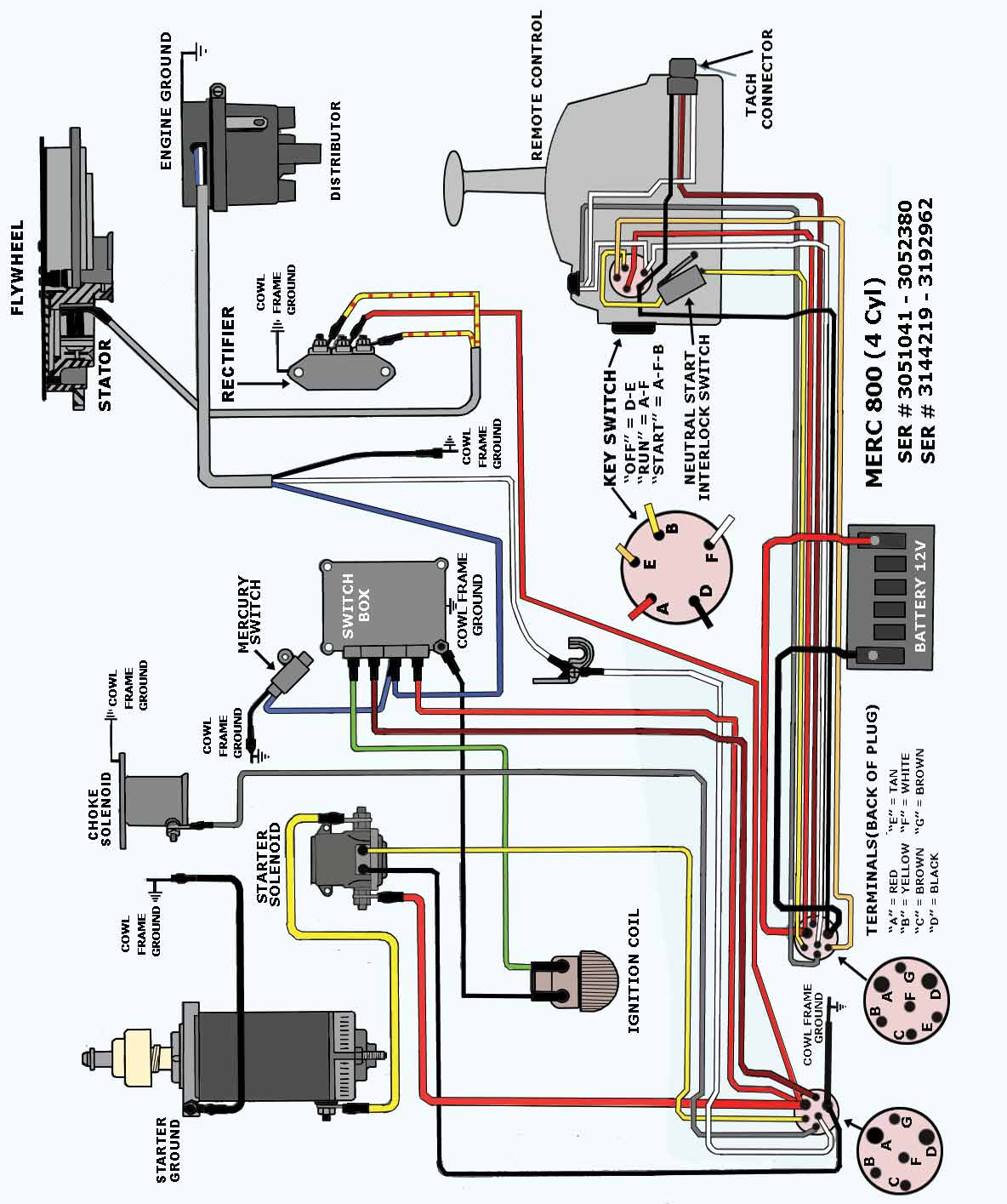
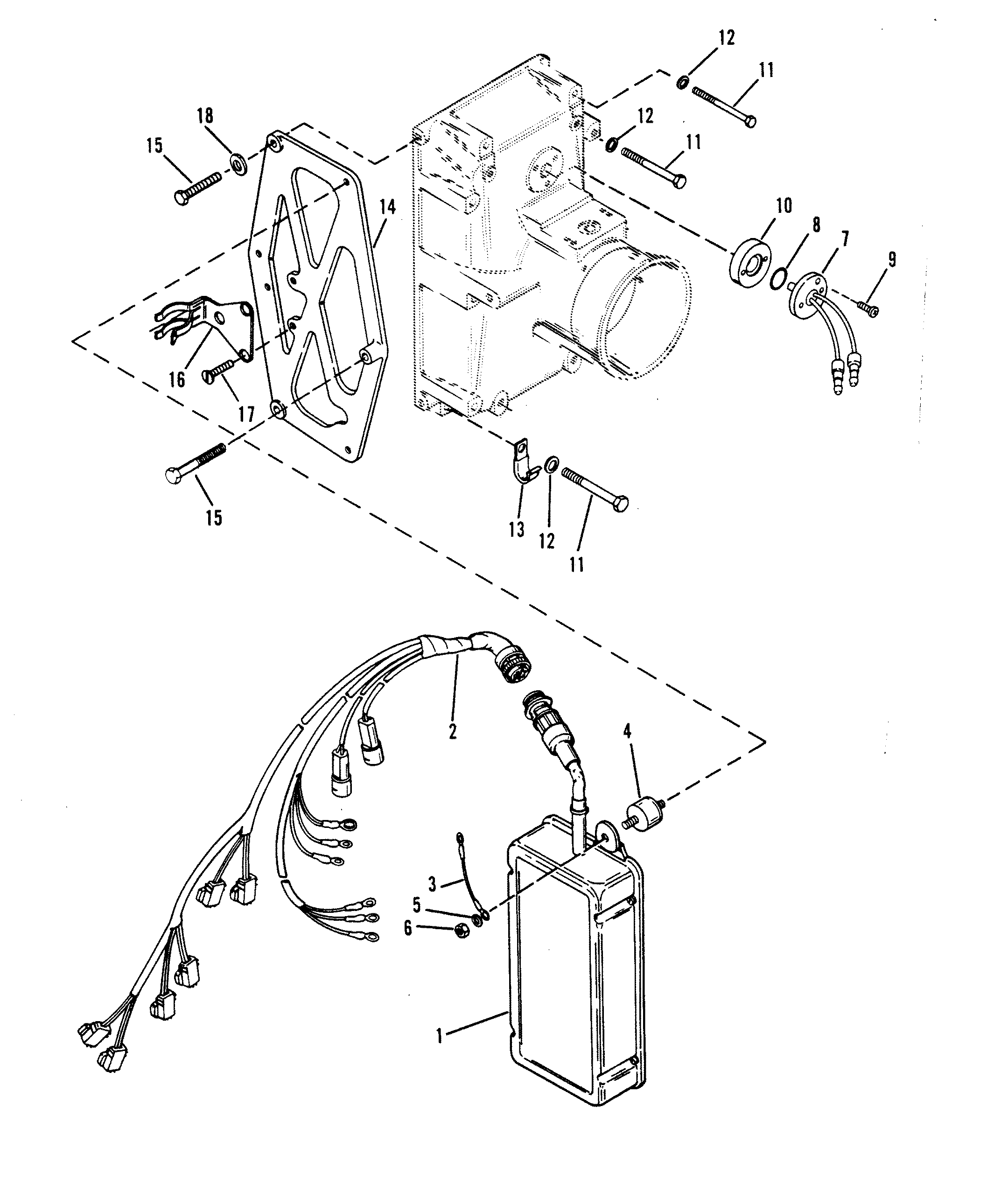
472 WIRING DIAGRAMS 75 AND 90 HP MODELS

Outboard Engine Wiring | TackleReviewer

I have 1987 mercury 175 black max .I want to remove the oil ...

Ignition Switch Troubleshooting & Wiring Diagrams | Kill ...

Single-Engine Controls Side Mount | Mercury Marine
FiberGlassics® - 1969 Merc 1250 - No spark - FiberGlassics ...
Mercury Side Mount Remote Control Trim & Tilt, 15ft, 8 Pin
Mercury Mariner 80's CDI outboard ignition Part 2: switch box/power pack/cdi explained

PREWIRED SURFACE MOUNT REMOTE CONTROL INSTALLATION ...
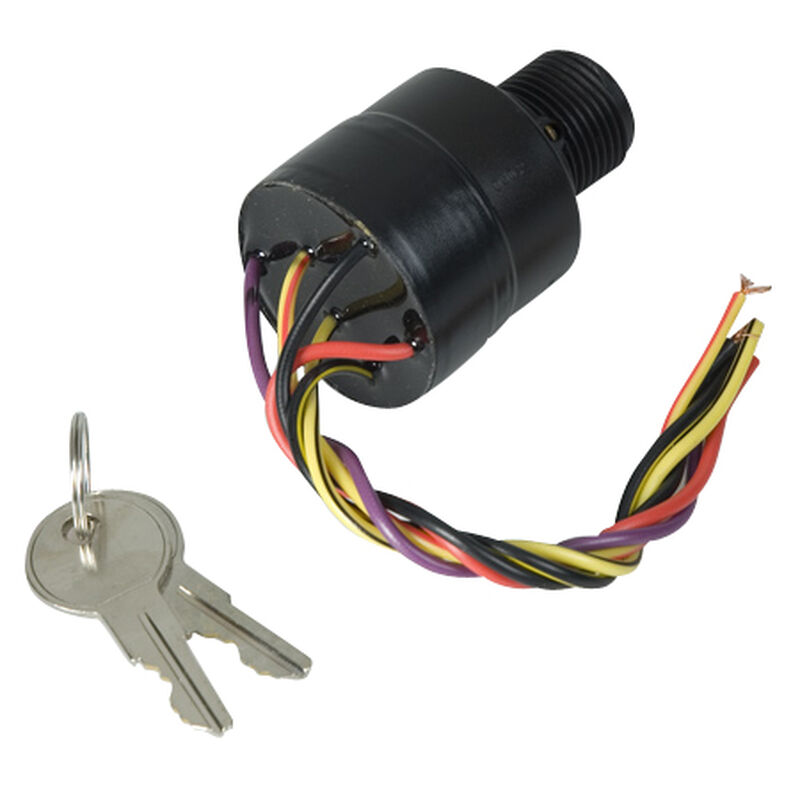
Mercury Ignition Switch (control box)

AIM Manual - Page 57 | Single-Phase Motors and Controls ...
Mercury Outboard Wiring diagrams -- Mastertech Marin
Wiring throttle control box help quicksilver 94 mariner 200hp ...
Mercury | RACE OUTBOARD | MERC/MAR 2.5L (EFI) | 0D030200 THRU ...
Yamaha wiring ? - RIBnet Forums
Mercury Verado Throttle Lever Fault on Second station - The ...

881170A15 Boat Motor Side Mount Remote Control Box With 8 Pin for Mercury Outboard Engine PT, Left Side

Buy Boat Ignition Switch with Key Replacement for Mercury ...

Mercury New OEM MercCruiser Side Mount Remote Control, Manual Start, 881170A6

Remote Control Box for Mercury Outboard 881170A15 Side Mount ...

Amazon.com: 881170A15 Boat Motor Side Mount Remote Control ...
Marine Rigging Guide K3.book(11Control.fm)

Boat Ignition Key Switch For Mercury Outboard Remote Control Box 87-17009A5
0 Response to "38 mercury control box wiring diagram"
Post a Comment