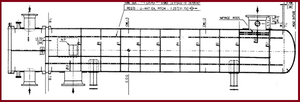
38 shell and tube heat exchanger diagram
Shell and Tube Heat Exchangers Shell and Tube heat exchangers are most commonly used in heating or cooling process fluids and gases. Typically found in applications where a need to heat or cool large volumes exist; however small volume applications are also very common. Shell and tube exchangers come in many variations to meet process requirements in almost every industry or ... Selection of Shell & Tube Heat Exchangers | TEMA Types ... On the NEN heat exchanger, the shell and the head is welded to the tubesheet. Typically, a cover plate design is provided to facilitate tube cleaning. This TEMA category, especially the NEN, is the lowest cost TEMA design per square foot of heat transfer surface.
Shell and tube heat exchanger - Wikipedia A shell and tube heat exchanger is a class of heat exchanger designs. It is the most common type of heat exchanger in oil refineries and other large chemical processes, and is suited for higher-pressure applications. As its name implies, this type of heat exchanger consists of a shell (a large pressure vessel) with a bundle of tubes inside it ...
Shell and tube heat exchanger diagram
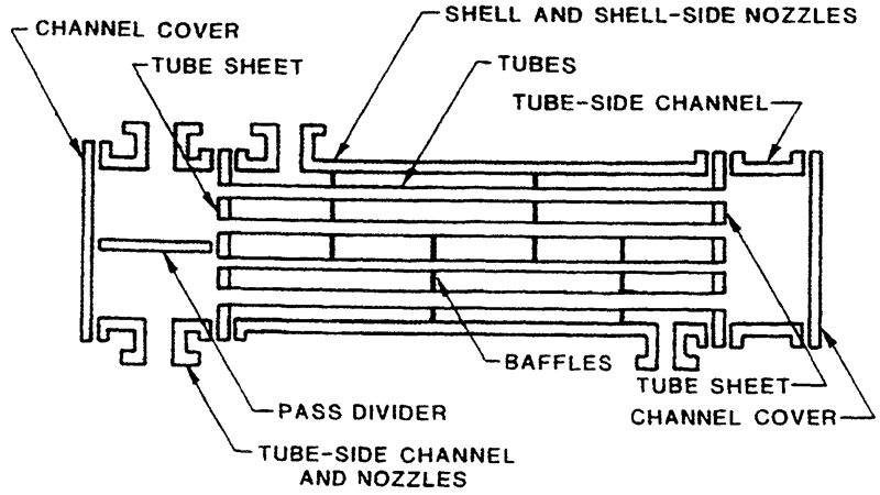
Floating Head Exchanger: Working & Diagram | Linquip The floating head type heat exchanger is a type of shell and tube heat exchanger in which the tube sheet assembly is independent and free to move within the shell or the shell cover. This exchanger is widely used for the service where the temperature is high between the shell and tube bundle that creates expansion issues. Typical shell & tube heat exchanger P&ID diagram - EnggCyclopedia This shell & tube heat exchanger diagram is actually simplified P&ID, depicting typical arrangement of piping, instrumentation and control systems around a shell & tube exchanger. This P&ID arrangement is a generic arrangement irrespective of the type of shell & tube exchanger used. Follow these guidelines to decide the fluid allocation in the ... PDF Shell-and-Tube Heat Exchangers - Clarkson University Most shell-and-tube heat exchangers have multiple "passes" to enhance the heat transfer. Here is an example of a 1-2 (1 shell pass and 2 tube passes) heat exchanger. As you can see, in a 12 heat exchanger, the tube- -side fluid flows the entire length of the shell, turns around and flows all the way back.
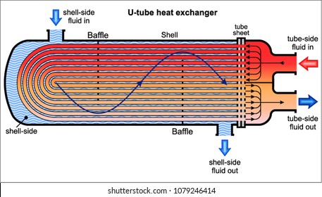
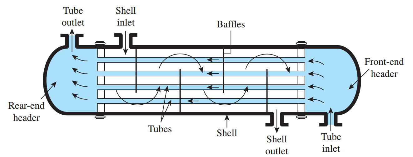
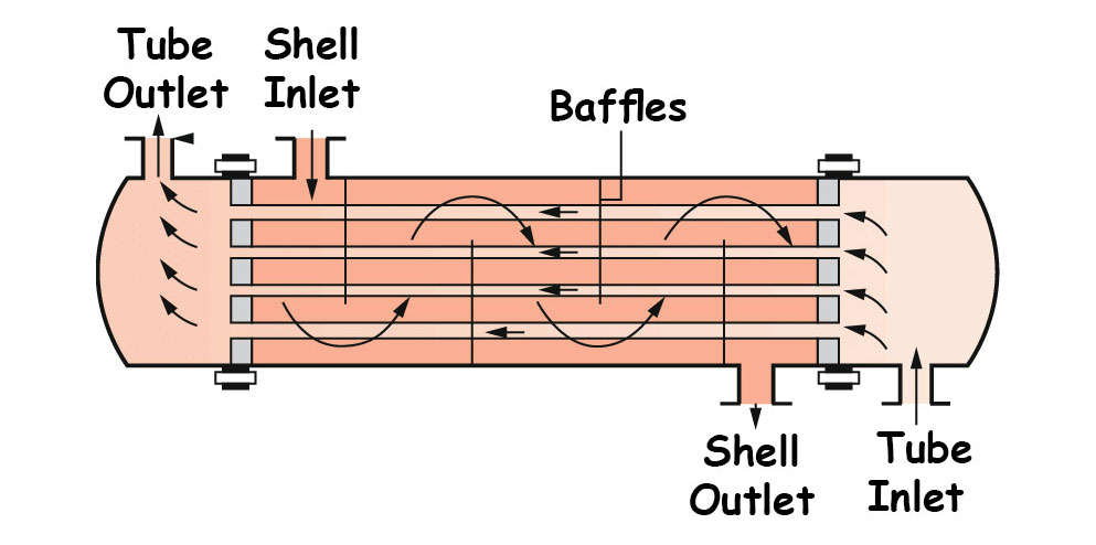
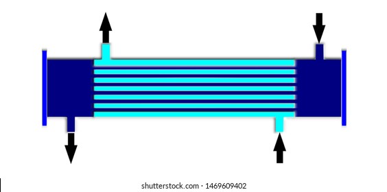
Shell and tube heat exchanger diagram. Funke | SHELL-AND-TUBE HEAT EXCHANGERS As the diagram shows, one medium flows through the shell chamber and the second medium through the tube chamber. The flow through the shell chamber is controlled by baffles, allowing as much cross flow to the tubes as possible. The form and spacing of the baffles is adapted to the application. Mechanisms of Heat Transfer - University of Oklahoma in a countercurrent heat exchanger. (b) A single-phase stream is heated from 120 to 220oC by condensation of saturated steam at 250oC and by subcooling the liquid to 225oC in a countercurrent heat exchanger. Heat Exchangers: The T-Q Diagram Examples: (a) (b) 250oC 100oC 200oC T Q 250oC 250oC 120oC 220oC T Q 225oC Condensing zone subcooling zone ... China Industrial Evaporator Shell and Tube Heat Exchanger ... China Industrial Evaporator Shell and Tube Heat Exchanger Tube Plate Heat Exchanger, Find details about China Heat Exchanger, Pressure Vessel from Industrial Evaporator Shell and Tube Heat Exchanger Tube Plate Heat Exchanger - Weifang Jinjian Titanium Equipment Co., Ltd PDF Chapter 4 Design Fundamentals of Shell-and-tube Heat ... specified) or the required length of the heat exchanger are calculated as output. In either case, the pressure drop of each stream will also be calculated. 'Design' is the process of determining all essential constructional dimensions of an exchanger that must perform a given heat duty and respect limitations on shell-side and tube-
Shell and tube heat exchanger.docx - Shell and tube heat ... Shell and tube heat exchanger Fluid flow simulation for a shell and tube style exchanger; The shell inlet is at the top rear and outlet in the foreground at the bottom A shell and tube heat exchanger is a class of heat exchanger designs. [1] [2] It is the most common type of heat exchanger in oil refineries and other large chemical processes, and is suited for higher-pressure applications. Shell and tube heat exchanger model. | Download Scientific ... Download scientific diagram | Shell and tube heat exchanger model. from publication: Modelling of Polymeric Shell and Tube Heat Exchangers for Low-Medium Temperature Geothermal Applications ... Answered: Question 16: In 1-1 shell and tube heat… | bartleby Engineering Chemical Engineering Q&A Library Question 16: In 1-1 shell and tube heat exchanger, steam is condensing on the shell side at TS°C and the cold fluid is heated on the tube side form t,°C to 12°C. The following equation relates t2 to the other variables. Ts - t In Ts - t2 W C, UA Where U is the overall heat transfer coefficient , 'A' is the heat transfer Area. Basics of Shell and Tube Heat Exchangers ... - What is Piping Typically a Shell and Tube Heat Exchanger consists of two-compartment / section one is shell side and other is channel/tube side Shell side section consists of the following components: Shell, Cover, Body Flange, Nozzles, Saddle support.
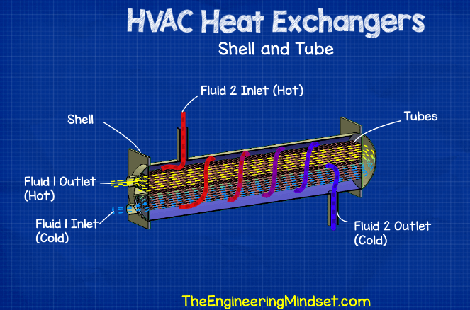
All About Shell And Tube Heat Exchangers - What You Need To Know As previously explained, the fundamental point of shell and tube heat exchangers is to pass a hot fluid through a cold fluid without mixing them, so that only their heat is transferred. The above diagram shows two inlets and two outlets, where each fluid starts at their respective inlet and exits the device at their outlets. Shell & Tube Heat Exchanger Piping: A brief Presentation ... Fig.1 :Diagram showing construction of a typical Shell and Tube Heat Exchanger These heat exchangers are generally designed, fabricated, inspected and tested as per API 660 / EN-ISO 16812 / TEMA. The DEP for the design & construction of the shell & tube heat exchanger is DEP 31.21.01.30 - Gen. (PDF) Process Life Cycle Solutions for the Case of ... The new exchanger designed using TASC has 135 m2 heat transfer area, nine baffles, AEU shell type, 920 tubes and the shell diameter of 889 mm. Table 4 shows the detailed design summary obtained from TASC. Shell and Tube Heat Exchanger: Design & Water Flow through ... A straight tube shell and tube heat exchanger has a tube sheet and a plenum at both ends as shown in the lower two diagrams. The straight tube heat exchanger shown at the right has one tube pass and the one on the left has two tube passes. Shell and Tube Heat Exchanger Design
SHELL AND TUBE HEAT EXCHANGER - ExtruDesign
SHELL AND TUBE HEAT EXCHANGERS - thermopedia.com A shell and tube exchanger consists of a number of tubes mounted inside a cylindrical shell. Figure 1 illustrates a typical unit that may be found in a petrochemical plant. Two fluids can exchange heat, one fluid flows over the outside of the tubes while the second fluid flows through the tubes.

Mechanical Engineering Network - simple shell & tube heat ...
Baffle (heat transfer) - Wikipedia Baffles are an integral part of the shell and tube heat exchanger design. A baffle is designed to support tube bundles and direct the flow of fluids for maximum efficiency. Baffle design and tolerances for heat exchangers are discussed in the standards of the Tubular Exchanger Manufacturers Association (TEMA).
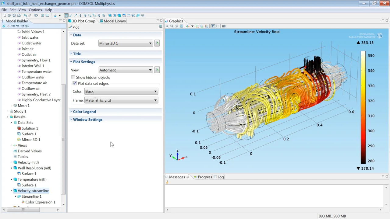
Model_Build_Shell and Tube Heat Exchanger Model Tutorial
SHELL AND TUBE HEAT EXCHANGER - ExtruDesign Shell-and-tube type heat exchanger having (a) 0°, (b) 30°, and (c) 60° baffle angles. The common focus of the publication is to predict the variation of LMTD, heat transfer coefficient, Nusselt number, and pressure drop with a change in values of Reynolds number for 0°, 30°, and 60° baffles situated in the heat exchanger as shown in Figure 1.

Single Tube Pass Single Shell Pass Counter Current Heat Exchanger
Shell and Tube Heat Exchanger: What Is It? Types, Process A shell and tube heat exchanger (STHE) is a type of heat exchanging device constructed using a large cylindrical enclosure, or shell, that has bundles of tubing compacted in its interior. The use and popularity of shell and tube heat exchangers is due to the simplicity of their design and efficient heat exchange rate.

Heat Exchanger - Types, Diagram, Working, Applications ...
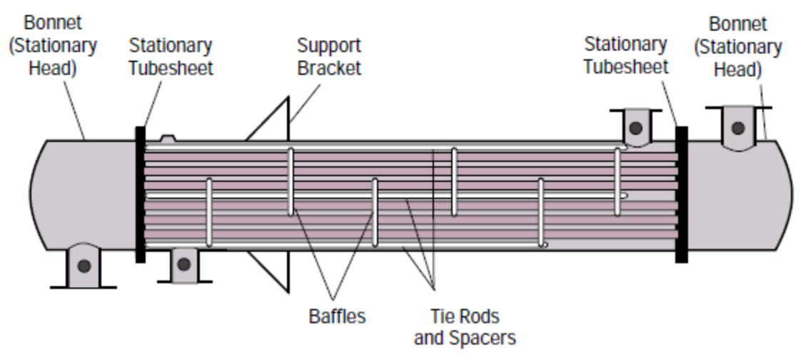
Shell & tube heat exchanger diagram - EnggCyclopedia Following diagram is the structure of a TEMA style shell and tube heat exchanger. The diagram itself is based on the TEMA standards. This diagrams illustrates all the important parts in the construction of a shell & tube heat exchanger, as per the TEMA standards. It also gives you the exact correct nomenclature for each of those parts.
Basics of Shell and Tube Heat Exchangers (With PDF) – What Is ...
PDF Section 5.4 Shell and Tube Heat Exchanger Corrected Example 5.2 Miniature Shell-and-Tube Heat Exchanger A miniature shell-and-tube heat exchanger is designed to cool engine oil in an engine with the engine coolant (50% ethylene glycol). The engine oil at a flow rate of 0.23 kg/s enters the exchanger at 120°C and leaves at 115°C. The 50% ethylene glycol at a rate of 0.47 kg/s enters at 90°C.

What is shell and tube heat exchanger? | How does a Shell and ...
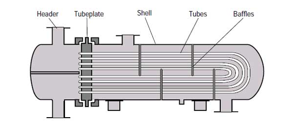
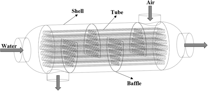
Heat Exchanger - Types, Diagram, Working, Applications ... Shell and tube heat exchanger consists of a bundle of round tubes placed inside the cylindrical shell. The tube axis parallels to that of the shell. One fluid inside the tubes while the other over the tubes. The main components of this type of heat exchanger are: i. Shell ii. Tube bundle iii. Front and rear headers of shell iv. baffles
Shell and tube heat exchanger Images, Stock Photos & Vectors ...
Shell and Tube Heat Exchanger - SysCAD Documentation Diagram. The diagram shows the default drawing of the shell and tube heat exchanger, with the required connecting streams. The user may also connect a vent stream to the unit. This is optional and allows non-condensable and excess vapour (typically steam) to be removed from the unit.

Exergoeconomic optimization of a shell-and-tube heat ...
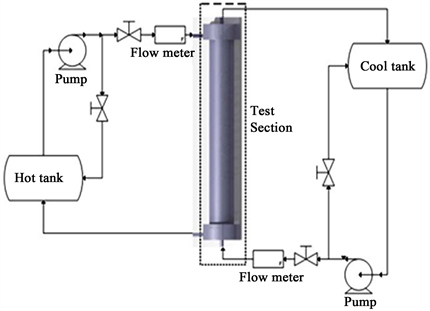
Shell And Tube Heat Exchanger Diagram | Products ... a) Diagram ; b) shape of heating cell from the front. Velocity profiles between two baffles in a shell and tube heat exchanger. Fig. 2 shows the schematic diagram of the experimen- tal shell and tube heat exchanger and the PIV system employed in this study. Applied Mechanics, Materials and Manufacturing.
Shell and Tube Heat Exchange Fundamentals, Design and Case ...
PDF Shell-and-Tube Heat Exchangers - Clarkson University Most shell-and-tube heat exchangers have multiple "passes" to enhance the heat transfer. Here is an example of a 1-2 (1 shell pass and 2 tube passes) heat exchanger. As you can see, in a 12 heat exchanger, the tube- -side fluid flows the entire length of the shell, turns around and flows all the way back.
All About Shell And Tube Heat Exchangers - What You Need To Know
Typical shell & tube heat exchanger P&ID diagram - EnggCyclopedia This shell & tube heat exchanger diagram is actually simplified P&ID, depicting typical arrangement of piping, instrumentation and control systems around a shell & tube exchanger. This P&ID arrangement is a generic arrangement irrespective of the type of shell & tube exchanger used. Follow these guidelines to decide the fluid allocation in the ...

Figure 1 from 7 Optimal Shell and Tube Heat Exchangers Design ...
Floating Head Exchanger: Working & Diagram | Linquip The floating head type heat exchanger is a type of shell and tube heat exchanger in which the tube sheet assembly is independent and free to move within the shell or the shell cover. This exchanger is widely used for the service where the temperature is high between the shell and tube bundle that creates expansion issues.
U Tube Heat Exchanger - Design for ASME / TEMA / API
All About Shell And Tube Heat Exchangers - What You Need To Know
Introduction - Heat Exchanger Design Handbook, Multimedia Edition

1-2 Shell & Tube heat exchanger (in hindi)

Shell and Tube Heat Exchanger

31 Shell And Tube Heat Exchanger- An Overview - Chemical ...

Volume XXIII: Components of Shell & Tube Heat Exchangers ...
shell and tube heat exchanger working principle explained ...

Shell and Tube Heat Exchanger in heat Transfer

What is shell and tube heat exchanger? | How does a Shell and ...
What is Shell and Tube Heat Exchanger - Definition
SHELL AND TUBE HEAT EXCHANGERS
Heat Exchangers - Introduction - Flow Arrangements and Types

Vector schematic diagram of shell and tube heat exchanger ...
5.1 Shell-and-Tube Heat Exchangers

Shell and tube heat exchanger - Wikipedia
Shell Tube Heat Exchanger Diagram Stock Illustration 1469609402
DESIGN OF SHELL AND TUBE HEAT EXCHANGER - EPCM Holdings
PFDs: Heat Exchangers Part 1

Basics of Shell and Tube Heat Exchangers (With PDF) – What Is ...

Diagram of mass flows for U-Tubes heat exchanger. | Download ...

What are Shell and Tube Heat Exchangers? Definition, Parts ...
Numerical study of shell and tube heat exchanger with ...
SHELL AND TUBE HEAT EXCHANGERS
Investigation of Shell and Tube Heat Exchanger with Disc-and ...
What is a shell and tube heat exchanger? - Quora
0 Response to "38 shell and tube heat exchanger diagram"
Post a Comment