41 intermatic t104r wiring diagram
How To Install an Intermatic T104 Timer - INYOPools.com wire gauge - The selection of wire gauge between the timer and pump depends on three factors: HP, supply voltage, and distance. An 115V pump will use twice the amperage as a 230V pump. If the distance to your pump is less than 50 feet, for a 1HP or less pump, on 230V you would need 14 gauge wire - for 115V you would need 12 gauge wire. Intermatic - main | Home ARISTA Support Center. Get the most out of your ARISTA Advanced Lighting Control System with these helpful resources and video tutorials. From initial setup to an easy handoff, we'll show you how to tailor ARISTA to meet your needs. learn more.
Intermatic Timer T104 Wiring Diagram - justussocializing.org Intermatic Timer T104 Wiring Diagram Wiring Diagrams February 01, 2022 00:07 Intermatic Timer T104 Wiring Diagram - One of the most hard automotive fix tasks that a mechanic or fix shop can recognize is the wiring, or rewiring of a car's electrical system.
Intermatic t104r wiring diagram
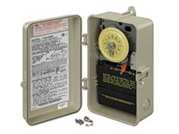
main | Control Panel with Two T104M Mechanisms - Intermatic T10000R Series Instructions. Features. Available with one or two heavy-duty time switch mechanisms. Accepts any combination of PF1000M, P1403ME, P1353ME, P4043ME, P4243ME, T100M or RC2000M Series mechanisms. Load center dead front has two knockouts for switches or GFCIs and one on the side. Wiring devices may be installed in these load centers ... Wiring Instructions for an Intermatic Timer - eHow.com Strip 1/2 inch of the covering from each insulated wire entering the Intermatic timer, with wire strippers. Two wire sets enter the timer. Each wire set contains two insulated and one bare wire. Step 5 Identify each wire terminal using the numbered labels, 1 through 4, for "Line" and "Load" terminal identification. Intermatic prints the labels ... PDF MODEL: T104 24 HOUR DIAL TIME SWITCH - Lowe's WIRING INSTRUCTIONS:To wire switch follow diagram above. Use solid or stranded COPPER only wire with insulation to suit installation. See gauge selection table for normal service applica-tions. To make power connections remove 1/2 inch of insulation from wire ends. Insert bare ends of wire under the pressure plate of terminals.
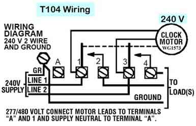
Intermatic t104r wiring diagram. How To Wire Connect Intermatic Pool Pump Timer SIMPLE ... Under a minute vid showing how to wire these timers (110/120V model) 24-Hour Mechanical Time Switch, 208-277 VAC ... - Intermatic Get recommended Intermatic products to use when replacing another manufacturer's product. Learn More. ... T104R Instructions. T100 Specifications. 24-Hour Mechanical Time Switch, 208-277 VAC, 60Hz, DPST, Indoor/Outdoor Metal Enclosure, 1 Hour Interval ... Wiring Option: Terminals: Resistive Load Ratings Ranges: 40 A, 120-480 VAC, 60 Hz ... Wiring intermatic T104R timer - Ask Me Help Desk Wiring intermatic T104R timer. Hi everybody! I work as a handyman. While trying to install an intermatic t104r timer, I found that th E clock does not work. I believe I followed the diagram. Manually It works, but I do not hear the clock ticking. Is it supposed to? The amps are 20, double pole. And iot is hooked up to two different runs of ... Intermatic T104r Wiring Diagram - schematron.org Intermatic T104r Wiring Diagram 16.04.201916.04.20192 Commentson Intermatic T104r Wiring Diagram LINE 2. / VOLT CONNECT MOTOR LEADS TO TERMINALS. "A" AND 1 AND SUPPLY NEUTRAL TO TERMINAL "A". WIRING. DIAGRAM. V 2 WIRE. The T Series Mechanical Time Switch has proven it can stand the test of time.
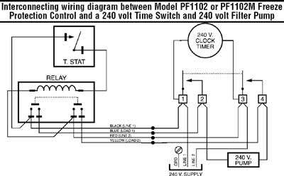
How do I wire a Intermatic DT104 for two 240 circuts. New ... Hey Mike - quick question about wiring an Intermatic T104R timer on a 40 Amp 240 V circuit. I've got 8/3 NMWU coming from the panel. The wiring diagram inside the timer's case is unclear as to what to … read more Intermatic T104R with 2 pumps & switch (diagram ... Electrical - AC & DC - Intermatic T104R with 2 pumps & switch (diagram) - I am replacing my old TORK pool timer with an Intermatic T104R DPST timer. I took it all apart last year and forgot how the wiring was done (I know, take pictures/label). Anyways, I drew out how I intend on re-wiring everything and was Seni Budayaku - cmpcmp.it The power supply for the heater timer can be the culprit as well. 120 VAC input with safe 12 VAC output. 19 Buy From Amazon Intermatic T104R 208 277 Volt DPST 24 Hour Mechanical Time Switch with Outdoor CaseProblems with Intermatic timers are caused by defective trippers, incorrect wiring, tripped circuit breakers, a faulty time clock motor and ... Intermatic Timer Wiring Diagram - Wiring Sample Intermatic pool timer wiring t104r won t turn pump on an wh40 water heater diagram how to connect t101 white ei200w electronic timers instructions operating r8806p101c supplementary p1353me manual wall digital switch t104 off t106r 24 hour dial et1105 outlet in lighting intelliflo vs whisperflo e1020 installation et1705c owner s reviews.
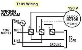
220\240 wiring diagram for a Intermatic T104R Timer ... Oct 15, 2015 - 220\240 wiring diagram for a Intermatic T104R Timer How to Replace an Intermatic T104M 240V (208 277 V) Pool ... WEBSITE: Video Index -- A list of all of my videos: ... PDF Model: T104r Lr3730 24 Hr. Dial Time Switch (Dpst) wiring diagram 240 v 2 wire and ground minimum copper wire size (awg) max. load (amp) min. insul-ation temp (°c) 75°c insulation max. motor load (hp) single phase 3 phase 120 v. 240 v. 208 v. 240 v. 14 12 10 8 15 20 30 40 60 60 60 75 1/2 1 2-2 2 1/2 3 5 n/a n/a pressure plate terminal screw make sure wire insulation clears pressure plate lr3730 Intermatic Timer Wiring Diagram - Studying Diagrams Intermatic Timer T104 Wiring Diagram Download It shows the components of the circuit as simplified shapes and the aptitude and signal links amongst the devices. A wiring diagram is a simplified standard photographic depiction of an electric circuit. An example of single-pole and three-way wiring follow. Connect ground wire to grounding terminal.
How To Install an Intermatic T104 Timer - INYOPools.com
24-Hour Mechanical Time Switch, 208-277 VAC ... - Intermatic Input Voltage Range(s) 208-277 VAC, 60 Hz: Maximum ON/OFF Operations: 12: Number Of Circuits: 1: Operation Mode: 24 hour: Resistive: 40 A, 120 VAC, 60 Hz, 40 A, 208 ...

Intermatic T104 Pool Timer - Off Tripper Turns Off The Clock ...
intermatic t104r for 110v - Trouble Free Pool The timer box says t104r and back of old timer motor wg-1573. The new one says wg-1573-5. The conduit line that runs to the switches (pump motor)has blue,green, (blower)red,white. The junction box has 4 wires 2 white,1 blue, 1 black. A blue and white run to the sprinkler timer.
How To Replace an Intermatic T104 Clock Motor - INYOPools.com
comparative cultural studies comparative literature media ... PDF. Postcolonial Studies in the Twenty-first Century: A Book Review Article of Literature for Our Times & Reading Transcultural Cities Alejandra Moreno Álvarez

How to wire Intermatic T104 and T103 and T101 timers
Intermatic T104 Electromechanical Timer, 208-277 V, 40 A ... Intermatic T104R 208-277-Volt DPST 24 Hour Mechanical Time Switch with Outdoor Case. ... Amazon selling it, and FedEx delivering to my door, it has been accomplished! The wiring diagram is a little difficult to comprehend but once you understand what it's showing you, it's simple and straightforward to hook up. ...

How to wire Intermatic T104 and T103 and T101 timers
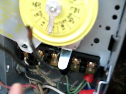
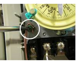
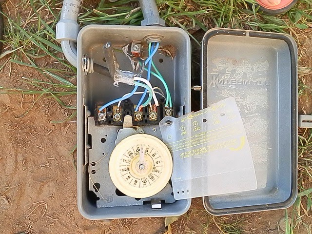
PDF How to operate and set T104 timer it was a circuit breaker box. Turn off power to work on timer wiring. To set timer, lift and rotate yellow dial until current time lines up with stationary silver pointer. Dial rotates each 24 hours, and keeps accurate time for years. Set ON and OFF trippers on outer edge of dial at the times you want to turn on and off.
Intermatic Pool Timer Troubleshooting - InTheSwim Pool Blog
PDF MODEL: T104 24 HOUR DIAL TIME SWITCH - Lowe's WIRING INSTRUCTIONS:To wire switch follow diagram above. Use solid or stranded COPPER only wire with insulation to suit installation. See gauge selection table for normal service applica-tions. To make power connections remove 1/2 inch of insulation from wire ends. Insert bare ends of wire under the pressure plate of terminals.

Intermatic T104 40 Amp 120-277VDC 24Hr Dial Time Switch ...
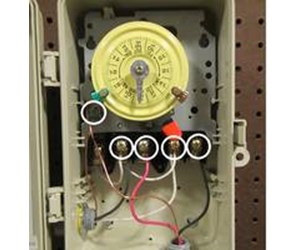
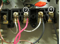
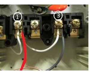
Wiring Instructions for an Intermatic Timer - eHow.com Strip 1/2 inch of the covering from each insulated wire entering the Intermatic timer, with wire strippers. Two wire sets enter the timer. Each wire set contains two insulated and one bare wire. Step 5 Identify each wire terminal using the numbered labels, 1 through 4, for "Line" and "Load" terminal identification. Intermatic prints the labels ...
Intermatic Pool Timer Troubleshooting - InTheSwim Pool Blog
main | Control Panel with Two T104M Mechanisms - Intermatic T10000R Series Instructions. Features. Available with one or two heavy-duty time switch mechanisms. Accepts any combination of PF1000M, P1403ME, P1353ME, P4043ME, P4243ME, T100M or RC2000M Series mechanisms. Load center dead front has two knockouts for switches or GFCIs and one on the side. Wiring devices may be installed in these load centers ...

How to wire Intermatic T104 and T103 and T101 timers

How to wire Intermatic T104 and T103 and T101 timers
Intermatic pool timer wiring - YouTube

How to wire Intermatic T104 and T103 and T101 timers
How To Install an Intermatic T104 Timer - INYOPools.com

How to wire Intermatic T104 and T103 and T101 timers

Guidance needed for wiring of pool pump timer bypass in 240V ...

Intermatic T104 208-277-Volt DPST 24 Hour Mechanical Time ...

Intermatic Pool Spa Time Switches Controls timers

Intermatic T104M Mechanical Time Switch Mechanism Only- Buy ...
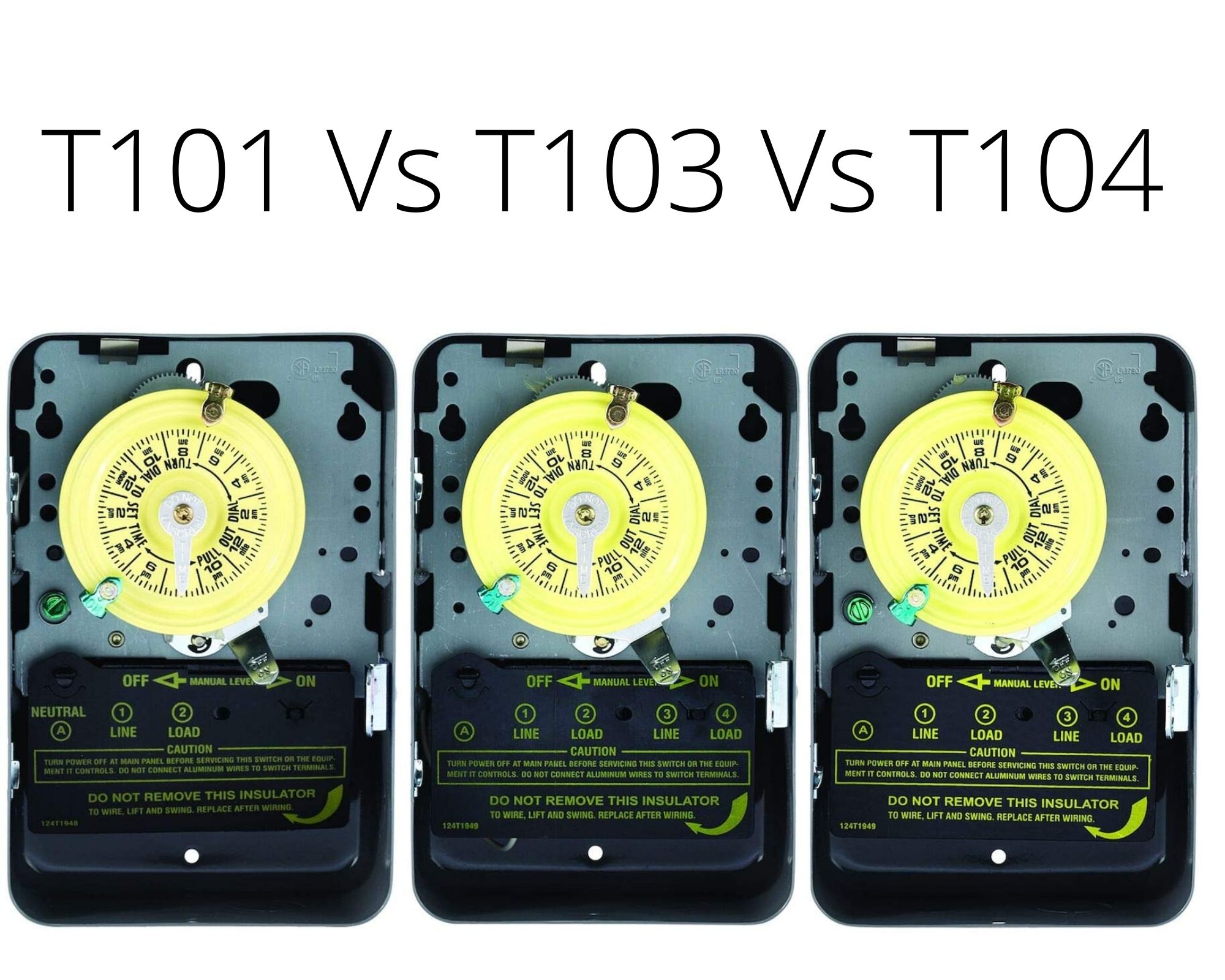
Which Intermatic Timer for Pool Pump? T101 or T103 or T104
How To Install an Intermatic T104 Timer - INYOPools.com
How To Install an Intermatic T104 Timer - INYOPools.com
How To Install an Intermatic T104 Timer - INYOPools.com

How to replace your mechanical time clock
Intermatic Pool Timer Wiring

http://waterheatertimer.org/How-to-wire-T104-Intermatic-timer ...

How to wire Intermatic ET series timer

How To Wire Connect Intermatic Pool Pump Timer SIMPLE SHORT VIDEO
How to wire dual T10404R clocks together and to a on off - Fixya

20 Most Recent Intermatic Timer T12404R Pool & Spa Questions ...

How to wire Intermatic T10604R control center | Power wire ...

Intermatic T104R Steel Enclosure 208-277V DPST Multi Use Timer

How to wire Intermatic T104 and T103 and T101 timers

How to wire Intermatic T104 and T103 and T101 timers

I have an intermatic T104 dial timer. Manual on/off works ...

How to wire Intermatic T104 and T103 and T101 timers

How to wire Intermatic T104 and T103 and T101 timers

Intermatic T10404R Two Timers in One for Pool & Spa

Intermatic T104 Pool Timer - Off Tripper Turns Off The Clock ...

How to wire Intermatic T104 and T103 and T101 timers

Pump makes noise on Hi when SWG is on, and Lo is off ...
Intermatic T104 digital replacement
0 Response to "41 intermatic t104r wiring diagram"
Post a Comment