42 common start run diagram
Electric Motor Starting Capacitor Wiring & Installation How to Identify the Start, Run, and Common Capacitor Terminals on an Electric Motor. The terminals on an electric motor should be marked as S - R - and C for Start, Run, and Common. But what if those markings have been lost. Before you can know how to connect a replacement start or run capacitor to a motor you must know which motor terminals ... Which compressor terminal is common, run and start? | DIY ... Determine the pair of terminals with the highest ohm -> The remaining third terminal is the common. 2. Determine which of the two remaining ones has the highest ohm when the other is the common -> that is the start. 3. The last one is the run. 4. At the contactor, you have two pair of cables (in my case, two red and two black). 5.
PDF Basic Wiring for Motor Contol - Eaton Wiring diagrams, sometimes called "main" or "construc-tion" diagrams, show the actual connection points for the wires to the components and terminals of the controller. They show the relative location of the components. They can be used as a guide when wiring the controller. Figure 1 is a typical wiring diagram for a three-phase mag-

Common start run diagram
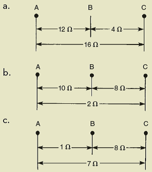
How to Add the Run Command to the Windows 10 Start Menu The Run command, known to most users as "the Run box," has long had a convenient top-level shortcut in the Windows Start Menu. While the Start Menu returned in Windows 10, the Run command didn ... Single Phase Motor Wiring Diagram With Capacitor Start ... Capacitor start run motor connection. Application of start and run capacitor for single phase motor. Read the wiring diagram on your appliance to understand the colors that the manufacturer designed for the three connections namely start run and common. Solved: Find the common, start, and run terminals of the ... Find the common, start, and run terminals of the following hermetic compressors. a. b. c. Step-by-step solution. Step 1 of 5 (a) The following is the diagram for the terminals in the hermetic run compressor: Figure 1. Chapter 8, Problem 41RQ is solved. View this answer View this answer View this answer done loading. View a sample solution.
Common start run diagram. PDF 800-2.0 Typical Wiring Diagrams for Push Button Control ... * The control station wiring diagram is a representation of the physical station, showing the relative positions of units, the suggested internal wiring, and connections with the starter. Symbols common to most circuits are explained on Page 5. Less common symbols are explained where they occur. NOTE - The symbols used in this publication were ... Capacitor Start Capacitor Run Motor Wiring Diagram Single Phase Motor Winding Resistance -Start Run Common Apr 03, 2018 · The motor in the picture with the extra two wire for the start capacitor is a little more tricky, but if you disconnect the capacitor and measure the resistance of ... Capacitor Start Capacitor Run Motor Wiring Diagram ... Guide to Track Markings - TrackInfo.Org The set that is equidistant from common finish line is the 2nd and 3rd passing zone for the 4x400 relay, while the set that is staggered (equidistant from the one-turn stagger line in each lane) is the first passing zone, still in lanes relative to the blue, 3-turn stagger start line. To run the mile on a metric track, there should be a ... What is Start Run Common In Single Phase Motor start run common diagram In the above example diagram, i shown two coil symbols, the running coil starting point is A and ending point is B.The starting coil starting point is C and ending point is D. So if we connect A and C then this will called the common because this point is connected with both coils.
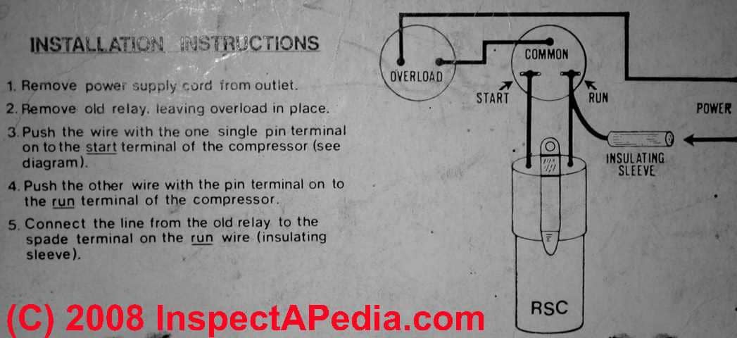
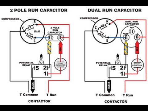
How do you connect a start and run capacitor? How to Wire Up a Start Capacitor. Turn off the electricity to the unit the motor operates. Inspect the start capacitor's wiring diagram. Push the wire terminal on the start capacitor relay's "Common" wire, usually the black wire, to the common terminal on the load side of the unit's contactor. Click to see full answer. How to identify compressor common, start, run terminal ... Compressor common, start, run identifyIn this video we explain how to identify compressor common start run with multimeter by testing their resistance For id... How to Wire Up a Start Capacitor - Hunker Step 7. Push the wire terminal on the start capacitor's second wire onto the run capacitor's common terminal, often labeled "C," "COM." The wire connected to the motor's run terminal, marked as "R" on the motor's wiring chart, and the wire going to the hot terminal on the load side of the contactor also connects to this run capacitor terminal. Identifying Compressor Terminals: Start, Run, and Main ... You need to figure out which posts correspond to the Start, Main, and Run windings 'cuz if'n you don't and you go and wire that relay/overload up wrong, well, you just went from a $30 easy-as-pie repair to a $300 rectal cramp.
Wye Start Delta Run Motor Wiring ... - Wiring Diagram Sample Size: 28.38 KB. Dimension: 300 x 288. DOWNLOAD. Wiring Diagram Images Detail: Name: wye start delta run motor wiring diagram - STAR DELTA Starter Will always work over with your 5HP above rated motors. File Type: JPG. Source: pinterest.com. Size: 52.05 KB. Dimension: 236 x 329. Embraco Compressor Wiring Diagram - Wirings Diagram Embraco Compressor Wiring Diagram - aspera compressor wiring diagram, embraco compressor wiring diagram, embraco egx70hlc compressor wiring diagram, Every electric structure is made up of various different parts. Each part should be placed and connected with different parts in specific way. If not, the arrangement won't function as it ought to be. PDF Installation Instructions - Fast-Stat Common Maker may not work as intended. 2. If the thermostat has power but the Common Maker will not activate the equipment, try reversing the wires in the thermostat cable. 3. At the thermostat base, place a jumper wire between the 'R' and 'W' terminals. This should cause the heating system to start. If the heating system does not start, Embraco Compressor Wiring Diagram - schematron.org the prongs on my compressor. embraco egy90hlp wiring diagram.Also there is a diagram on the back of the package the shows you where to put the common, start, and run lead on the compressor, if it is a embraco compressor invert the diagram to match the stud coming off compresser. Compressor Wiring Diagrams: Refrigerant.
Heating and Cooling Essentials 5e, Textbook Page 493 (511 of 800)
Single phase ac compressor wiring diagram I have a ac compressor which have common start run therminals in compressor and a relay and a start capacitor . *** help me to fix all in the compressor. There is nothing written in the compressor that I can find the common , start and run. ... Single phase ac compressor wiring diagram.

Pin by julio perez on refrigeration/aircon | Refrigeration ...
Start Capacitor Wiring Diagram - easywiring Start capacitor wiring diagram. Push the wire terminal on the start capacitor s second wire onto the run capacitor s common terminal often labeled c com the wire connected to the motor s run terminal marked as r on the motor s wiring chart and the wire going to the hot terminal on the load side of the contactor also connects to this run ...
![DIAGRAM] 240v Airpressor Wiring Diagram FULL Version HD ...](https://i.pinimg.com/736x/b3/38/d7/b338d73b5f79b01f78dc6d2bac449071.jpg)
DIAGRAM] 240v Airpressor Wiring Diagram FULL Version HD ...
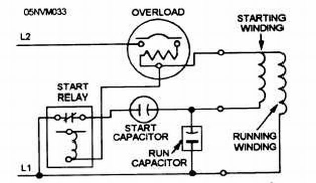
Cscr Wiring Diagram - schematron.org This is a common question, and the answer may have a significant effect on how your motor runs, depending on its size and application. The diagram in Figure 1a shows the potential relay connected to a motor with a start and run capacitor. Note that the potential relay's contacts are connected in .

3 Way Switch Wiring Diagrams - Do-it-yourself-help.com
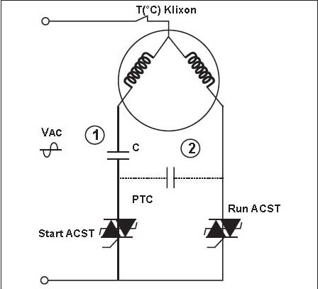
Capacitor-Start Capacitor-Run Induction Motor The phasor diagram of the capacitor-start capacitor-run motor is shown below. At starting both the capacitors are in the circuit, therefore, the phase angle φ is greater than 90°. When the starting capacitor (C S) is disconnected from the circuit, then the phase angle becomes 90° electrical.
Electric Motor Starting Capacitor Wiring & Installation
Single Phase Motor Wiring Diagram With Capacitor - Wirings ... Single Phase Motor Wiring Diagram With Capacitor - baldor single phase motor wiring diagram with capacitor, single phase fan motor wiring diagram with capacitor, single phase motor connection diagram with capacitor, Every electrical arrangement is made up of various unique pieces. Each component ought to be placed and linked to different parts in particular manner.

Btu Buddy 189: Heat Pump Motor Wiring Problems | 2018-12-24 ...
Capacitor Start Motor Wiring Diagram - Wiring Diagram Single Phase Capacitor Start Capacitor Run Motor Wiring Diagram - Capacitor Start Motor Wiring Diagram. Wiring Diagram will come with a number of easy to stick to Wiring Diagram Guidelines. It really is intended to aid all the common user in developing a suitable system. These directions will likely be easy to understand and use.
3 capacitor 240v motor, how to hook up capacitors? On ...
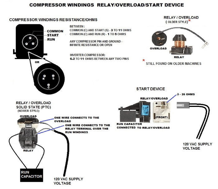
Tech Tip: Compressor Common - Run - Start | Ferguson HVAC When tripped, you will read infinity between start to common and run to common, but you will read resistance between run and start. You will have to let the compressor cool and the overload to should reset before further testing. Compressors can take hours to cool down and the overload to reset. Formula: CS + CR = SR.
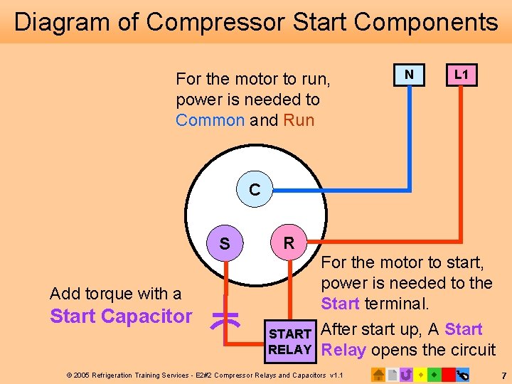
E 2 Motors and Motor Starting 2 Compressor
Heatcraft Unit Cooler Wiring Diagram Heatcraft Unit Cooler Wiring Diagram. Wiring at the unit cooler (s) will be as follows (see wiring diagrams). • High voltage - There may be high voltage on the defrost heater relay and the fan relay. to your Heatcraft Refrigeration Products Sales Representative. Warranty Consult the wiring diagram in the unit cooler and in the condensing unit ...

Start Capacitor and Inrush Facts & Myths - Part #3 - HVAC School
How to Find Common, Start, and Run on a PSC Compressor ... In this HVACR Training Video, I show how to Measure Resistance Readings on the PSC Compressor Terminals in order to determine which tab is Common, Start, and...

Unique Single Phase Capacitor Start Capacitor Run Motor ...
On a refrigerator compressor, which is the common, start ... The run terminal is usually on the right and the start terminal is on the left. To check this, (with the refrigerator unplugged) you could take resistance readings on the terminals. From the common to the start terminal, you should measure between 3 to 11 ohms. From the common to run terminal, you should measure between 1 and 5 ohms.

Single Phase Motor Winding Resistance -Start Run Common
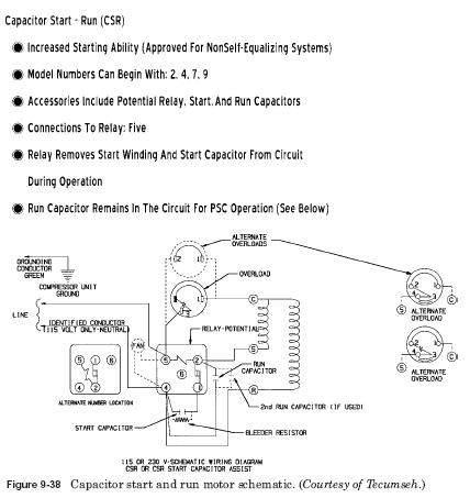
PDF 3 Compressor Motor and Component Information sor motors and are very common up through 5 HP. Figure 3-4. CSR motor diagram. Relay - Potential Compressor - Unit Ground Line 1 Line 2 Ground Start Winding Main Winding Control External or Internal Thermal Protector. C S R. Figure 3-5. PSC motor diagram. Compressor - Unit Ground External or Internal Thermal Protector Run Capacitor Line 1 Line ...
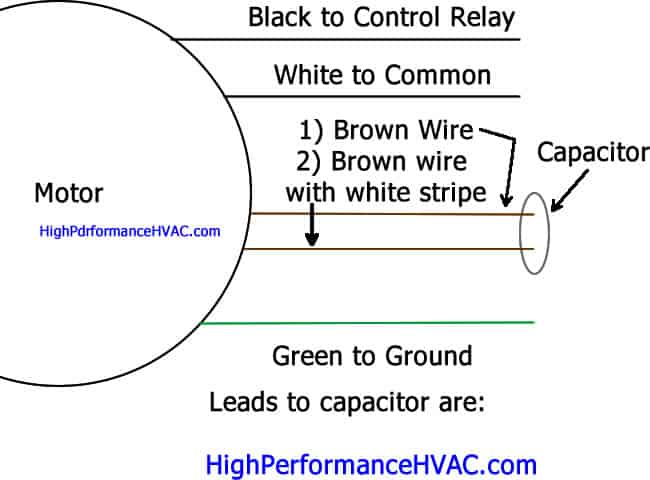
How to Wire a Run Capacitor to a Motor Quality Wiring 101
Solved: Find the common, start, and run terminals of the ... Find the common, start, and run terminals of the following hermetic compressors. a. b. c. Step-by-step solution. Step 1 of 5 (a) The following is the diagram for the terminals in the hermetic run compressor: Figure 1. Chapter 8, Problem 41RQ is solved. View this answer View this answer View this answer done loading. View a sample solution.

10.3 Potential Relays - 10.4 Solid-State Starting Relays and ...
Single Phase Motor Wiring Diagram With Capacitor Start ... Capacitor start run motor connection. Application of start and run capacitor for single phase motor. Read the wiring diagram on your appliance to understand the colors that the manufacturer designed for the three connections namely start run and common.
Basement air trouble - Winnebago Owners Online Community
How to Add the Run Command to the Windows 10 Start Menu The Run command, known to most users as "the Run box," has long had a convenient top-level shortcut in the Windows Start Menu. While the Start Menu returned in Windows 10, the Run command didn ...

How To Check Compressor Windings With Multimeter

A Schematic diagram of a capacitor start and run type SPIM ...
Start Capacitor Vs. Run Capacitor Why You Can't Store A/C Power In A Capactor

Types of Single Phase Induction Motors- Applications

Compressor electrical parts diagrams - www.itieffe.com

Single Phase Capacitor Start Capacitor Run Motor Wiring ...
Solved: Find the common, start, and run terminals of the ...

Practical Machinist - Largest Manufacturing Technology Forum ...

I had to replace the capacitor of a 3 ton Fedders condenser ...

VTM state transition diagram. NonT: Not executing a ...
Hermetic Compressor Motor Types: Motor run capacitor Starting ...

Single Phase Motor Winding Diagram | Main/Auxiliary Winding ...
S ecu reS tart
To read a diagram, we must understand a circuit. Here is ...

Pin on cooling

Good Sam Club Open Roads Forum: Coleman 7335(?) Series ...

Capacitor Start Capacitor Run Motor - Pro Electric Academy ...
Is Your Refrigerator Compressor Faulty? Here's How to Test It

Potential for Good and Evil (The Hard Start & Potential Relay ...

Single Phase Wire Diagrams

Motor Start and Run Capacitors.
Index of /wp-content/uploads/2011/03

compressor power connection... - AC technician /Electrician ...

Start run wiring diagram for Century 3hp 1081 pool/spa pump

Capacitor Start, Capacitor Run Motors
Hard Start|Hard Start Kit|Start Capacitor|Compressor for air ...

AC Single-Phase Motors (part 2)

Single Phase Motor Winding Resistance -Start Run Common
0 Response to "42 common start run diagram"
Post a Comment