42 scully system wiring diagram
PDF Installation Instructions Wiring Instructions It is highly recommended to use FloTech FT401 jacketed 7-conductor cable when wiring a new system. FloTech cable is designed to be oil, UV, and abrasion resistant. We incorporate a noble tin plated stranded copper wire which resist corrosion. These features will provide years of reliable service. 1. PDF Liquip Sales Pty Limited Engineering Department 13 Hume ... Refer to system wiring diagrams 10 Monitor to truck plug For TP104 2 wire system, use 10 core overall screened. For TP103 5 wire system, use 5 core overall screened. Both cases minimum conductor size of each core is 1.5mm2 or 18AWG
Support/Resources - Scully Signal POLICIES Conflict Minerals Statement Scully Ordering Terms and Conditions Scully Website Terms and Conditions DOCUMENTATION Storage Tank Equipment ST-15 WX Datasheets: ST15WX_US ST15WX_International ST15WX_French ST15WX_German ST15WX_Russian ST15WX_Spanish ST15WX_Portuguese Manuals: ST15 WX_Manual Safety Manual: ST15WX_Safety Manual SP-O Single Sensor Mounting Holder…
Scully system wiring diagram
PDF 8460SRC Replacement Chassis for Scully ST-6 and Biclops ... Figure 4 System Control Diagram ... Figure 6 ST-6 System Wiring ... verification circuitry compatible with systems manufactured by the Scully Signal Company. Upgrade of your existing system is possible following the instruction covered under the GROUND VERIFICATION section. PDF CIVACON OPTI-THERM RACK MONITOR SYSTEM and ASSOCIATED ... 3 SYSTEM CONTROL DIAGRAM FIGURE 2 - SYSTEM CONTROL DIAGRAM Notes: 1 - Control Equipment and Electrical Apparatus connected to the Rack Monitor should not use or generate more than 250 Volts. 2 - Installation should be in accordance with NEC ANSI/NFPA 70 and ANSI/ISA RP12.6 . In Canada, the PDF Installation Instructions API 5 wire FT101 sensors. FloTech recommends wiring the sensors to the FT208 Monitor using FT404 11 conductor cable for up to 8 compartment systems. FloTech FT404 cable is color coded to ease installation and troubleshooting. A color coded wiring schematic is provided in the back of this manual. TB5 Socket Connections
Scully system wiring diagram. Get to Know the Scully ST-47 Groundhog The Scully Groundhog enables you to have complete confidence that grounding to the vehicle's frame has been accomplished. The Groundhog is an intelligent system that continuously and automatically monitors the grounding connection during the entire loading operation. If an earth tie-in is broken, the product is designed to immediately shut ... PDF 61680 Intellitrol 2 RevE For Print - Scully System Setup 21. 4.1 CPU Jumper Settings 4.2 VIP List ... evaluated by exida and certi˜ed as part of a SIL 2 Over˜ll Prevention System when used in conjunction with Scully Sensors. This functional safety assessment and certi˜cation is an IEC 61508 standard ... (2-Wire, Optic or Therm.) Sculcon Field Wiring Diagram with Deadman. 9.8 Dwg. No ... Scully Wiring Diagram - Free PDF File Sharing scully load anywhere monitor ... 4402-4402 wiring diagram installed by civacon ground lug white (ground) orange red (power) field splice (ground) [Filename: Section5.pdf] - Read File Online - Report Abuse. Civacon Section A Petroleum Trailer Parts. Scully Intellicheck 2 Monitor 2-wire system 09107 - Overfill and retain 09109 - Overfill only ... PDF Scully Portable Liquid Level Sensor Technical Datasheet Scully control monitors, which incorporates Dynacheck®. Dynacheck® circuitry monitors the sensor, wiring, connections, and its own operation 30 times per second. When a sensor comes in contact with liquid, or if an unlikely fault occurs within the system itself, Dynacheck® signals for the immediate shutdown of the loading operation and/or
PDF Scully Load Anywhere Wiring grounding systems ali yaqoob, scully overfill sensor 5 wire overfill probe 7 length, scully system wire diagram wiring source, intellitrol 2 overfill prevention and ground verification unit, 1965 chevy impala ignition switch wiring diagram ebooks, intellitrol2 scully signal, scully load anywhere system eneric ltd, tanker parts store scully overfill PDF Scully ST-35 Technical Manual - jmesales.com the vehicle via a Scully plug and cable assembly. The system incorporates Scully's unique and exclusive Dynacheck® concept. To ensure that it will always detect an over˜ll condition, the controller uses pulsed signals which continuously check the entire system operation including the controller, wiring connections and sensors. If a sensor comes PDF Document in Microsoft Internet Explorer - SafeRack require additional wiring connections to both the API plug and automation system. Communication of Ground Verification and Overfill PERMIT is achieved through separate relay output contacts. Monitor status is displayed through the existing red and green status lights on the Scully enclosure. IntelliCheck®2 - Scully Signal OVERFILL ONLY - 2-Wire System Kits. Each system kit includes an on-board monitor, the appropriate number of 2-Wire Optic Overfill Sensors for each compartment, installation accessories including the proper length and number of conductors of color coded cable, 30 crimp-on connectors, 16 compression fittings, and one 1⁄2-ampere fuse with holder.
PDF Single Point Overfill Prevention Controllers The system incorporates Scully's unique and exclusive Dynacheck concept. To ensure that the system will always detect an overfill condition, the controller uses pulsed signals which continuously check the entire system operation. The controller, wiring, connections and sensors are checked for faults up to 30 times per second. If a sensor Scully Green Thermistor Plug & Coiled Cord w/ 4 J-Slot ... Scully Blue Optic Plug & 30 ft. Coiled Cord w/ 3 J-Slot Pins & 6 Contact Pins for Scully Systems. As Low As: $490.00. Add to Cart. Civacon Green Thermistor Plug, Coiled Cord, and Break-Away Plug w/ 13 Contact Pins for Civacon or Scully System. As Low As: $866.47. PDF Scully ST-47C Groundhog Scully ST-47C Groundhog Technical Manual ST-47C Series Self-Proving Vehicle Earthing Veri˜cation System Scully Signal Company / Tel. 617 692 8600 / Fax. 617 692 8620 / MaxSafety 800 2 SCULLY (272 8559) 70 Industrial Way, Wilmington, MA 01887-3479, USA / SYSTEMS sales@scully.com / Seymour Duncan Little 59 For Tele Wiring Diagram Yetter Seed Train Wiring Diagram; Scully Grounding System Wiring Diagram; Mercruiser Thunderbolt Iv Ignition Module Wiring Diagram; Color Wiring Diagram Cf Moto150 Cdi Box; 1999 7.4 Fuel Injector Harness Wiring Diagram; Kazuma Falcon 110 Wiring Diagram; Polaroid Pbt 3032 Wiring Diagram; Jayco Lift System Diagram; Maytag #3406015 Wiring Diagram
60982 ST35_RevK_Final for Print
PDF Overfill System Training First determine the type of system (type of sensors used) • 5‐Wire Sensor Systems (Like the Civacon Liberty or Scully LA/GA) ‐Series wired 5‐wire sensors ‐Sensors operate and test just like a straight 5‐wire system • 2‐Wire Sensor Systems (Like the Civacon ROM II or Scully IntelliCheck 2
Section 5 Overfill Protection
VDC001403 User Manual 8 Scully Signal VDC T—Ring wiring is provided via a short harness and must be extended using the coil harness and two conductor shield cable Scully part number 000766. T~Ring wiring should run along the vehicle side on which the fuel tank inlet is located. T-Ring harness should have a minimum clearance of 2" from all other wires and the harnesses.

Scully ST-47 "Groundhog" Basics - [PDF Document]
PDF Scully Sockets: Truck Mounted Over˜ll Prevention System ... Scully Sockets: Truck Mounted Over˜ll Prevention System Connectors Description Part Number SJ-8S SJ-6S SJ-6 SJ-6W SJ-6SO SJ-6X SJ-6W Optic Socket, WOGA Pattern, API Optic Standard 07974 SJ-6SO Optic Socket, Scully Pattern 07973 SJ-6X Optic Socket, SAE J560 Pattern 08199 SJ-8S Thermistor Socket, API Thermistor Standard 07716 SJ-6S Thermistor Socket, API Thermistor Standard 07720

Support/Resources - Scully Signal
PDF Scully ST-47 Groundhog Technical Manual Scully ST-47 Groundhog Technical Manual ST-47 Series Self-Proving Vehicle Grounding Veri˜cation System Scully Signal Company 70 Industrial Way, Wilmington, MA 01887, USA • 800-272-8559 • sales@scully.com •
scully
Scully System Wiring Diagram - Wiring Diagram Scully System Wiring Diagram. 28 checkmate system with retain and overfill manualzz untitled assistance ressources scully signal sockets truck mounted prevention connectors electronic component co wiring diagram circuit ground png 554x900px vdc001403 user manual 8 60982 st35 revk final for print ft208 5 wire installation instructions st 47 ...
61680_Intellitrol 2_RevE_For Print
docs.lib.purdue.edu › clcweb › vol18comparative cultural studies comparative literature media ... PDF. Postcolonial Studies in the Twenty-first Century: A Book Review Article of Literature for Our Times & Reading Transcultural Cities Alejandra Moreno Álvarez

Scully ST-47 "Groundhog" Basics - [PDF Document]
› shows › fox-filesFox Files - Fox News Jan 31, 2022 · FOX FILES combines in-depth news reporting from a variety of Fox News on-air talent. The program will feature the breadth, power and journalism of rotating Fox News anchors, reporters and producers.

US20100185334A1 - Truck compartment verification system with ...
Scully Grounding System Wiring Diagram - schematron.org Scully Grounding System Wiring Diagram. doubt that the grounding systems at your terminals are performing their The Scully Groundhog, when wired as a self-proving system, cannot be fooled by. Can be "straight' wired system (diagram next page) . 2-Wire Sensor Systems ( Like the Civacon ROM II or Scully IntelliCheck 2 Ground Bolt wired to Pin # 9.

Re-wiring Your Cafe Racer I Motorcycle Electrics 101 I ...
› createJoin LiveJournal Password requirements: 6 to 30 characters long; ASCII characters only (characters found on a standard US keyboard); must contain at least 4 different symbols;

SOLVED: I need a wiring diagram for the steering wheel - Fixya
unobus.co.jp岡山市、美作市、赤磐市、備前市 ... - 宇野バス 宇野バス自慢のアイテムを紹介しながら、宇野バスの経営哲学や社会問題に対する意見を一般の皆様にお伝えする場として【宇野バスのアイ】をはじめました。

Support/Resources - Scully Signal
PDF Fault-finding, Tanker overfill protection 2 wire system. 4 Scully Optical 6.5 to 9.5 6.5 to 9.5 5 Scully Elec. Dummy 4.5 to 7.0 4.5 to 7.0 Compartment 3 has the higher voltage reading out of the three (3) Scully optical probes, so it is replaced and that fixes the problem. The probe is not necessarily faulty, the monitor channel many need an adjustment or there was a poor wiring connection in the tanker.
VDC001403 User Manual 8 Scully Signal
Scully - Overfill and Ground Scully plugs and cables are the product of years of industry experience and offer durable, efficient operation.They are designed for use only with the intrinsically safe output circuits of Scully's ST-35, ST-15 and Intellitrol ®.Scully Plugs and Cables are used to connect the Scully loading rack control monitor to the vehicle mounted socket ...

Thermistor Sensors - Acme Fluid Handling
Home - Scully Signal Scully's inhouse manufacturing is vertically integrated with our own machine shop, diecast, electronic, and mechanical assembly. We have access to components and plenty of production capacity. Scully's core systems include—but are not limited to—overfull prevention, static ground proving, retained product monitoring, and oil delivery.

2007 F-150 Supercrew Reverse Lights Wiring Diagram ...
bugs.openjdk.java.net › browse › JDK-8141210[JDK-8141210] Very slow loading of JavaScript file with ... Nov 03, 2015 · FULL PRODUCT VERSION : java version "1.8.0_66" Java(TM) SE Runtime Environment (build 1.8.0_66-b17) Java HotSpot(TM) 64-Bit Server VM (build 25.66-b17, mixed mode ...
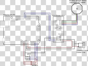
Electronic Component Scully Signal Co Wiring Diagram ...
PDF Scully Groundhog LINE This system is ideal for top loading or applications where a Scully Overfill Prevention System is not in use. The control monitor connects to a heavy duty Sculcon® junction box with attached cable and special quick release snap-on plug. The Scully Ground Plug connects to a specially designed electronic Scully Ground Ball mounted on each vehicle.

SCULLY - OVERFILL AND GROUND |
PDF Installation Instructions Remanufactured Veeder-Root ... Wiring the Overfill without an Acknowledgement Switch Wire used for this installation must have a rating of at least 90°C, must be 14 or 16 AWG and be color coded. Use the color illustration below as guide. However, the colors used are for clarity. The actual wire colors you use may be dictated by national and local codes. 1.

Scully Overfill Prevention
PDF Installation Instructions API 5 wire FT101 sensors. FloTech recommends wiring the sensors to the FT208 Monitor using FT404 11 conductor cable for up to 8 compartment systems. FloTech FT404 cable is color coded to ease installation and troubleshooting. A color coded wiring schematic is provided in the back of this manual. TB5 Socket Connections
Intellitrol®
PDF CIVACON OPTI-THERM RACK MONITOR SYSTEM and ASSOCIATED ... 3 SYSTEM CONTROL DIAGRAM FIGURE 2 - SYSTEM CONTROL DIAGRAM Notes: 1 - Control Equipment and Electrical Apparatus connected to the Rack Monitor should not use or generate more than 250 Volts. 2 - Installation should be in accordance with NEC ANSI/NFPA 70 and ANSI/ISA RP12.6 . In Canada, the
Maintenance & Operating Instructions
PDF 8460SRC Replacement Chassis for Scully ST-6 and Biclops ... Figure 4 System Control Diagram ... Figure 6 ST-6 System Wiring ... verification circuitry compatible with systems manufactured by the Scully Signal Company. Upgrade of your existing system is possible following the instruction covered under the GROUND VERIFICATION section.

SCULLY ST-47 SERIES TECHNICAL MANUAL Pdf Download | ManualsLib

Sockets Rev-A US English | PDF | Electrical Connector ...

OVERFILL PREVENTION – Kalymnos Fuel Engineering
Untitled
HHP Hand Held Programmer User Manual SECTION 3 CONFIGURATION ...

SCULLY - OVERFILL AND GROUND |

Scully IntelliCheck®3 Overfill Control Unit

Electronic Component Scully Signal Co Wiring Diagram ...
Intellitrol®
61053 Rev J_ST47 Manual_For Print
scully

SCULLY ST-35C-120 EL TECHNICAL MANUAL Pdf Download | ManualsLib
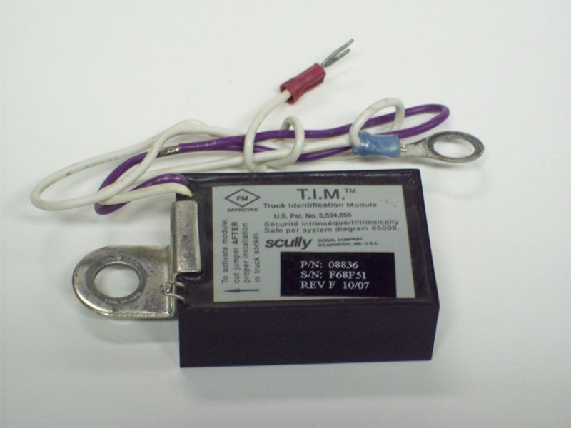
SCU08836

Wiring diagram for Huada motor set roadster HD-6420 - Fixya

SCULLY SP-FU SERIES INSTALLATION/WIRING INSTRUCTIONS Pdf ...

Support/Resources - Scully Signal

The wiring diagram for connecting the experimental cell ...
Section 5 Overfill Protection

Support/Resources - Scully Signal

SCULLY - OVERFILL AND GROUND ·

SCULLY - OVERFILL AND GROUND |

Support/Resources - Scully Signal

Support/Resources - Scully Signal
0 Response to "42 scully system wiring diagram"
Post a Comment