42 temperature gauge wiring diagram
PDF 3 Gauge Wiring Kit Instructions - GlowShift This wire can be connected to any ground source on your vehicle or you can wire this directly to the negative side of the battery. 4. Orange Wire (Optional) - Connect the orange wire to your positive 12 volt headlamp source wire to dim the gauges while operating at night. 5. Blue Wire - Connects to Gauge 1 Sensor (Optional). Fuel and Temp gauge wiring questions - Old Willys Forum The temperature gauge gets it power from the regulated output of the fuel gauge so the jumper strap connecting the A terminals of the fuel and temperature gauges must be left intact. The gauge needles shouldn't have moved from the off position until you take a resister from the S terminal to ground. Fuel Gauge
Yamaha Outboard Tilt And Trim Gauge Wiring Diagram Electric Temperature Gauge Wiring Diagram Google Search Gauges Wire Electricity from . 97 F150 Fuse Diagram Inside Hold the power trim and tilt unit in a vise using aluminum plates a on both sides. Yamaha outboard wiring diagram pdf A Beginner s Overview of Circuit Diagrams.

Temperature gauge wiring diagram
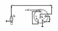
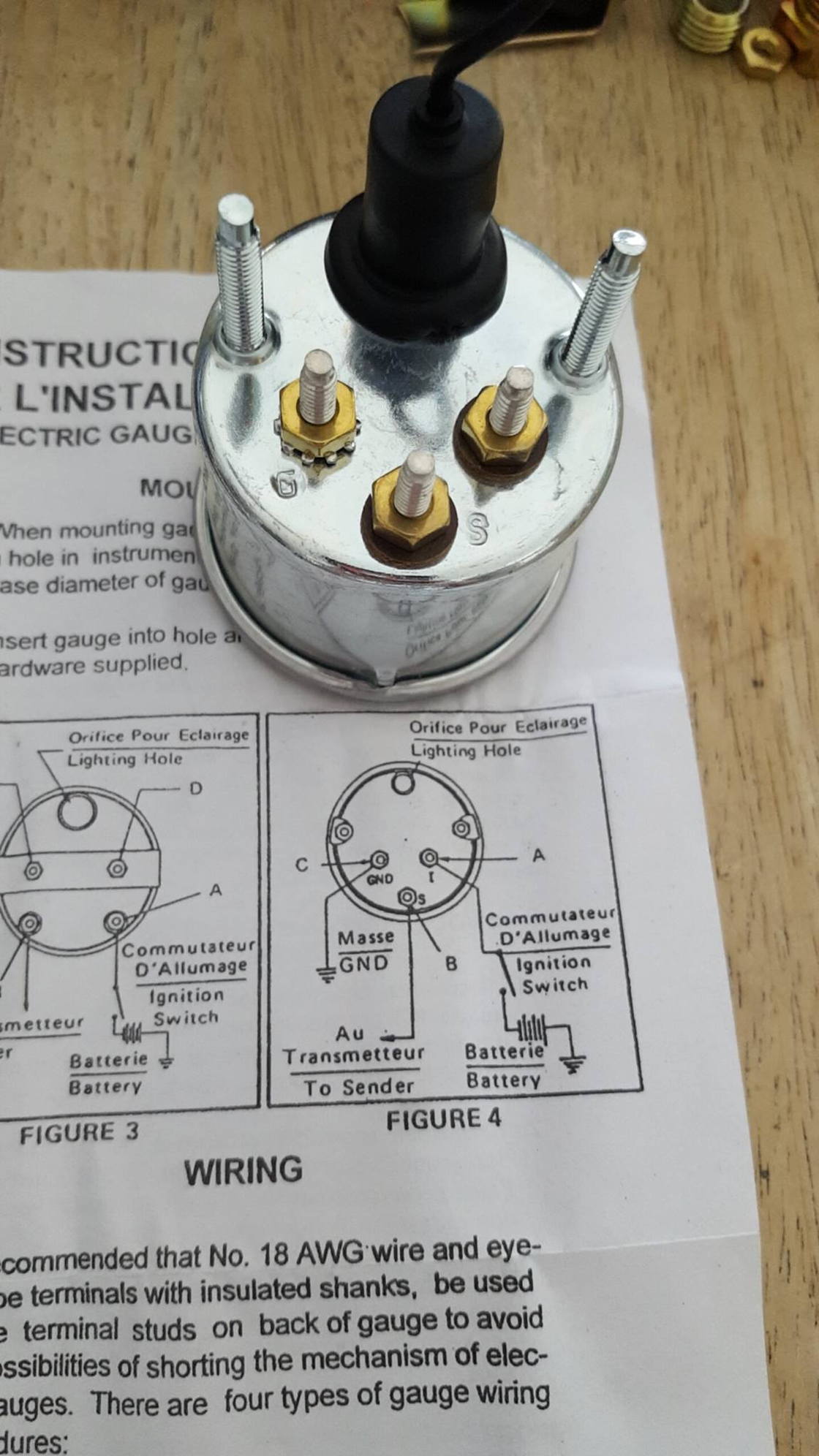
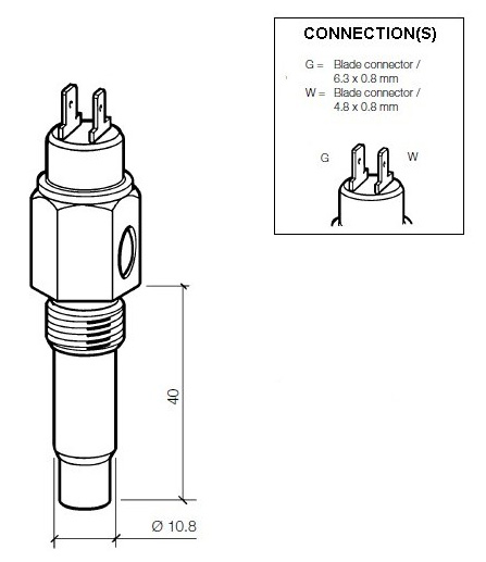
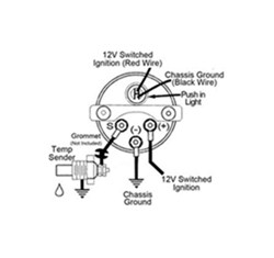
PDF UNIVERSAL WIRING HARNESS - Wiring Wizard Tan Gas sender wire Connect to the 'SENDER' location on gauge. White Tach sender wire Connect to the 'SENDER' location on gauge. (-) Black Ground Connect to each gauge (ground location) as shown in diagram. Pink 12 volt ignition feed Connect to each gauge (12 v location) as shown in diagram. PDF HELP?: GENERAL APPLICATION: Installation Instructions ... TEMPERATURE GAUGE WIRING (Figure 3): 1. Disconnect negative (-) battery cable. 2. Using 18-ga. wire, connect the (G) terminal to a clean (rust/paint-free) ground surface near the temperature sender. 3. Using 18-ga. wire, connect the (I) terminal to a switched +12V source. 4. Using 18-ga. wire, connect the (S) sender terminal of the Vdo Water Temp Gauge Wiring Diagram - schematron.org Vdo Water Temp Gauge Wiring Diagram Vdo Water Temp Gauge Wiring Diagram 15.10.2018 3 Comments I. Installing the VDO Universal Temperature Sender Proper Wiring Between Gauge and Temperature Sender. 3. connected to the gauge (see Diagram B). 5. sender since the sender tip or bulb will not be immersed in the water flow.
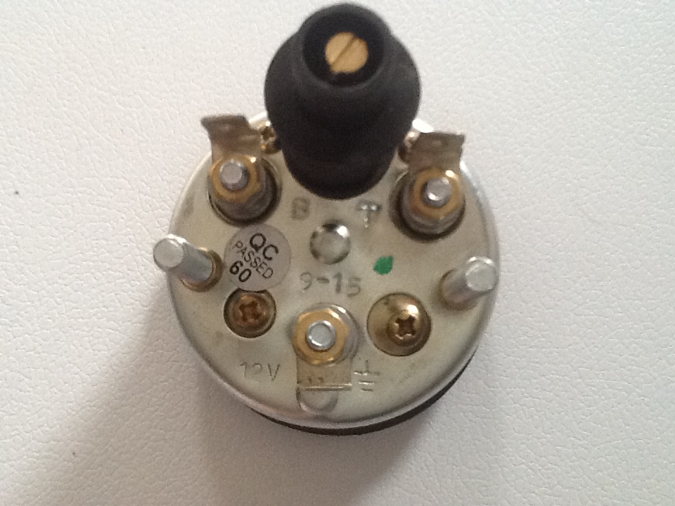
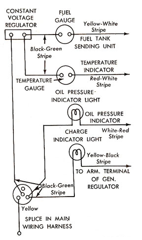
Temperature gauge wiring diagram. PDF 1957 Chevy Installation Manual Revision 010615 Temperature Gauge Wiring 1) Always disconnect the vehicle battery before wiring any gauge. 2) Connect a switched +12VDC power source to the post marked "I" on the back of the temperature gauge. 3) Connect a good chassis ground to the post marked "G" on the back of the temperature gauge. Product Manuals | Qualitrol Corp Product Manuals. Here you can find product manuals for varying Qualitrol products. Most manuals are available in multiple languages. Make sure to check back often as more are being added all the time. Gauge Wiring Diagrams - ETB Instruments 80 & 100mm Electronic Speedometer Mk3 - General Wiring Diagram & Instructions, Hall-effect M8 sensor (340 002) + Magnetic Induction Sensors. 433kb. 80 & 100mm Electronic Speedometer Mk3 - Hall-effect Gear Tooth Sensor (340 017) + Speedometer Disc / Bolt Heads. 366Kb. 80 & 100mm Electronic Speedometer Mk3 - Rover SD1 Sensor. PDF 1969 Chevelle SS Gauge Conversion Diagram TEMPERATURE GAUGE 1. Locate the original dark green wire found at location T-C in the fuse block bulkhead connector as shown on page 4 and remove it from the connector. Plug the loose terminal on the dark green wire (35A on page 3) from the Dash Side Gauge Harness Extension into the fuse block bulkhead connector at location T-C as shown on page 4.
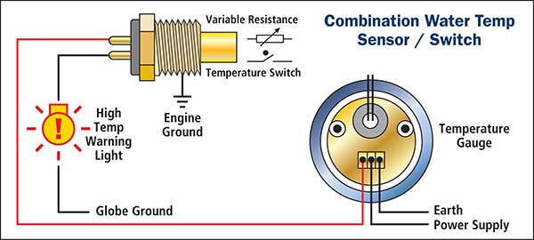
Wiring Diagrams - Classic Instruments Wiring Diagrams. 01 Six Gauge Set Wiring Diagram 11/10/09. 01 Six Gauge Set Wiring Diagram 5/9/19. Six Gauge Set Wiring Diagram SNWH03 . All-American 3200/6400 Package Guide Rev 2/27/13. Download 3200 Wiring Instructions Rev 2/7/13. Download 6400 Wiring Instructions Rev 2/7/13 . Senders . SN11 Low Volt Light Rev 7/12/12 PDF Bosch Custom Gauges Installation Instructions - CARiD.com the positive side (Diagram 2A) of the lighting circuit: Diagram 2A Connect the black wire into the circuit between the dimmer control and the dash lights. Con - nect the red wire to the fuse box so that the wire only receives +12-volt power when the dash lights are turned on. GAUGE DASHBOARD BRACKET NUTS & WASHERS TOP VIEW Diagram 1 Diagram 2B ... 1, 2, & 3 Wire Coolant Temperature Sensor Wiring Diagram Earth Signal Wire for Cluster Mounted Temperature Gauge 3 Wire Coolant Temperature Sensor Wiring Diagram The two wires, a “5-volt reference”, and a “ground wire” go to the ECU, and the third wire “Earth Signal Wire for Temperature Gauge” goes to the cluster-mounted temperature gauge by providing an earth signal to the temperature gauge. Cylinder head temperature gauge wiring diagram for Westach ... Normally a Rotax air cooled engine should read between 350F to 375F on a cylinder head temperature gauge (CHT) . When an engine overheats the amount of expansion between these parts is greater than allowed - the piston becomes too tight in the cylinder and the piston "seizes' creating permanent damage to the piston and or cylinder wall.
Temperature Gauge Wiring Diagram | autocardesign Jan 26, 2020 · Temperature Gauge Wiring Diagram. Wiring Diagram January 26, 2020 02:52. Temperature Gauge Wiring Diagram Bobcat T200 Wiring Diagram Wiring Diagram Name. Temperature Gauge Wiring Diagram – wiring diagram is a simplified all right pictorial representation of an electrical circuit. It shows the components of the circuit as simplified shapes, and the aptitude and signal associates amid the devices. Temperature Gauge Wiring Diagram For Your Needs Temperature Gauge Wiring Diagram. Print the electrical wiring diagram off in addition to use highlighters to trace the routine. When you use your finger or even stick to the circuit along with your eyes, it may be easy to mistrace the circuit. A single trick that I use is to printing the same wiring diagram off twice. How to Wire a Temperature Gauge - It Still Runs Guide the wire up into the dashboard and through the back side of the gauge hole. Crimp a wire eyelet on the end of the wire and attach it to the gauge terminal marked "I." Fasten a nut on the gauge terminal with a socket. Step 10 Push the gauge into its mounting hole. Dolphin Gauges Wiring Schematic - IOT Wiring Diagram IOT Wiring Diagram. Dolphin Instruments Gauges. Dolphin gauges 1947 1948 1949 1950 tpi need help wiring instruments lower radiator installation instructions for 3 8 ...
Gauges
General Motors temperature gauge troubleshooting ... The first place to start is at the temperature-sending unit. Remove the wire from the temperature-sending unit located on the engine (typically a dark green wire). Then connect the wire to a good ground. You can do this by using a jumper wire. Check the gauge, if the needle points to "Hot", replace the sending unit.

89 ford f150 351 does wire from temp sensor go straight to ...
Vdo Temperature Gauge Wiring Diagram/ Vdo Temperature Gauge Wiring Diagram/ the sender body, or backwards, the fuel gauge will read “FULL” when the temperature Refer to the wiring diagram, Diagram G. Wire gauges in series from. Temperature gauge, pressure gauge, rudder angel gauge, A specialized technician should install the product. according to the electrical wiring diagram.

Corvette Temperature Gauge Required Input 1979 | Willcox ...
Temperature Gauge Wiring Diagram - Ford Mustang Forum You can find the wiring diagrams on this website 1967 Mustang Wiring and Vacuum Diagrams Also, I want to say, you may want to keep that other temp gauge connected. The original temp gauge has some problems with accuracy and it may lead you to think that your car is running hot. You can find many posts about such problems on this forum. Take care MJ
Installation Instructions
Vdo Water Temp Gauge Wiring Diagram the sender body, or backwards, the fuel gauge will read "full" when the temperature sender refer to the wiring diagram, diagram g. wire gauges in series from a positive (+) temperature: needle to the temperature of the engine water.using the expertise we've gained in developing specialized solutions for many of the world's leading manufacturers, …
How to Install Auto Meter Direct Fit Dash Gauge Panel (97-06 ...
PDF Wiring Diagrams & Harnesses for Ford Tractors Wiring Diagrams & Harnesses for Ford Tractors . Contributed by Neil Reitmeyer, Rob G, Don & Derek Barkley, Dan Dibbens, Ed Gooding, and Tyler Neff • 9N/2N Wiring Diagrams . 9N Wiring Harnesses • 8N Wiring Diagrams • 12 Volt Conversion Wiring Diagrams: 8N Wiring Harnesses
How To Install A Transmission Temperature Gauge
Autometer Water Temp Gauge Wiring Diagram Aug 15, · Autometer Pyrometer Wiring Diagram auto meter ficial site trade in any aftermarket gauges for credit on new autometer gauges 15 trade in trade up read more auto Autometer Pyrometer Wiring Diagram Isspro Electric Water Temp img source: diagramweb.net Autometer Pyrometer Wiring Diagram As Well As Temperature Gauge img source.

Coolant temp sensor wiring confirmation needed - NASIOC
Vdo Temperature Gauge Wiring Diagram/ - schematron.org Jan 10, 2018 · Wiring diagrams VDO cockpit international (for engine coolant) The electrical oil temperature gauge has been designed for land-bound vehicles or.THE INSTRUCTIONS FOR INSTALLATION AND ELECTRICAL WIRING FOR THE INSTRUMENT KIT FOLLOWS. USE IS RESTRICTED TO 12 VOLT NEGATIVE GROUND ELECTRICAL SYSTEMS. Temperature Gauge (21/16" diameter) 1 6.
Wiring Water Temp Gauge : TR2 & TR3 Forum : Triumph ...
Troubleshooting Oil Pressure and Water Temperature Gauges There are a several checks you can perform to verify the gauges in your instrument cluster are working correctly. These can be helpful if you're trying to de...
How does 63-67 Temp Gauge Work? - CorvetteForum - Chevrolet ...
Glowshift Trans Temp Gauge Wiring Diagram The wiring diagram is easy to follow, but the instructions weren't clear as to. Our GlowShift support page delivers a multitude of helpful tools that are essential for our GlowShift customers. Whether you need to access GlowShift install. Elite 10 Color Transmission Temperature Gauge. For Product Numbers: GS- ET12 & GS-EWT Wire Harness Color Code.

1, 2, & 3 Wire Coolant Temperature Sensor Wiring Diagram
smiths water temperature gauge wiring diagram - Wiring Diagram Wiring Diagram Water Temperature Gauge By facybulka Posted on May 24, 2018 Using automotive grade wiring 18 gauge. Boat wiring and gauges. Water Temperature Gauge Wiring Diagram Rotax 582 Water Temperature 52mm […] Smiths Water Temperature Gauge Wiring Diagram By facybulka Posted on September 27, 2016

Transmission Tempature Gauge
Vdo Water Temp Gauge Wiring Diagram - schematron.org Vdo Water Temp Gauge Wiring Diagram Vdo Water Temp Gauge Wiring Diagram 15.10.2018 3 Comments I. Installing the VDO Universal Temperature Sender Proper Wiring Between Gauge and Temperature Sender. 3. connected to the gauge (see Diagram B). 5. sender since the sender tip or bulb will not be immersed in the water flow.
Installation Instructions Typical Layout
PDF HELP?: GENERAL APPLICATION: Installation Instructions ... TEMPERATURE GAUGE WIRING (Figure 3): 1. Disconnect negative (-) battery cable. 2. Using 18-ga. wire, connect the (G) terminal to a clean (rust/paint-free) ground surface near the temperature sender. 3. Using 18-ga. wire, connect the (I) terminal to a switched +12V source. 4. Using 18-ga. wire, connect the (S) sender terminal of the
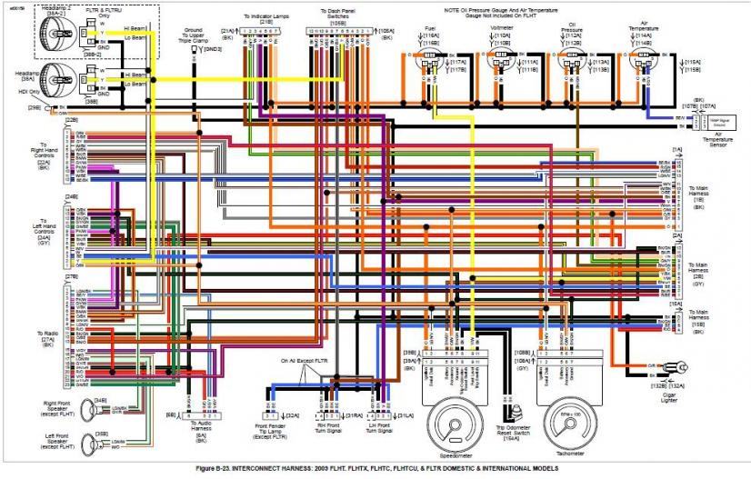
Fig. 20 Water Temperature Gauge Circuit Diagram
PDF UNIVERSAL WIRING HARNESS - Wiring Wizard Tan Gas sender wire Connect to the 'SENDER' location on gauge. White Tach sender wire Connect to the 'SENDER' location on gauge. (-) Black Ground Connect to each gauge (ground location) as shown in diagram. Pink 12 volt ignition feed Connect to each gauge (12 v location) as shown in diagram.

TAKE IT IN TOP!: Wiring Diagram for Smiths Classic Gauges
gauge wiring assistance... : MGB & GT Forum : MG Experience ...
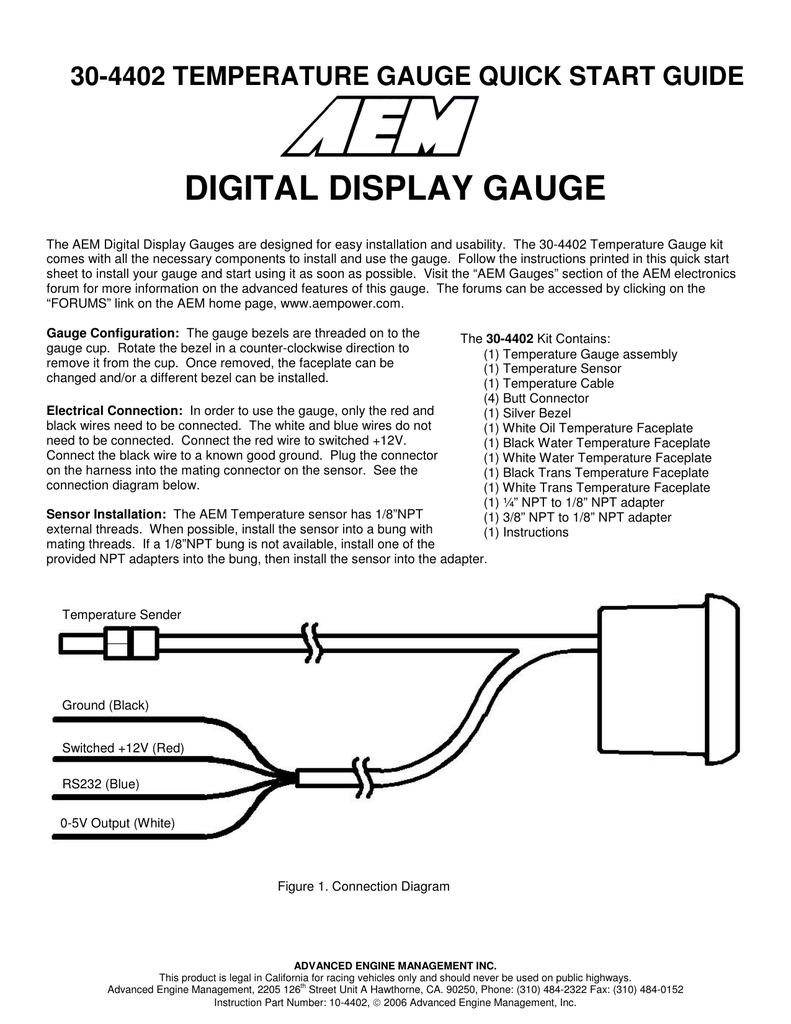
DIGITAL DISPLAY GAUGE
basic wiring - water temp sensor/gauge - help a complete ...

SOLVED: Temp gauge wiring diagram - Fixya

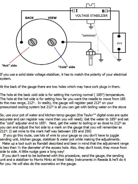
Recalibrating the water temperature gauge | CSR175
Transmission Temperature Gauge - FreeAutoMechanic

Smiths Temp Gauge Wiring - Problems, Questions and Technical ...
03-'05) - Coolant temp gauge dying - video inside | Subaru ...

2” Electrical Water/Oil Temperature Gauge | Bosch Style Line
Vdo temp sensor gauge | YBW Forum
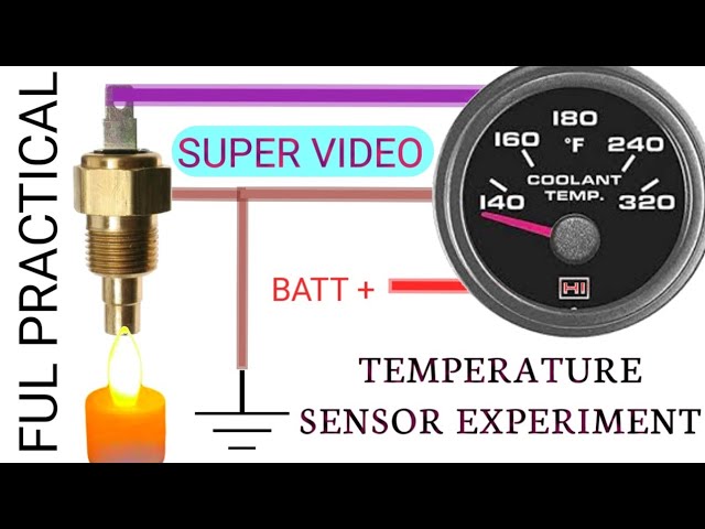
temperature sensor experiment. engine coolent temperature ...

Elite 10 Color Transmission Temperature Gauge
Oil temperature gauge problem- need help - Page 2 - Harley ...
Temperature gauge wiring - Boat Building & Maintenance ...

VDO Cylinder Head Temperature Gauge Installation Instructions ...
42 Draft Designs
Temp Gauge following Speedometer | Subaru Outback Forums

fitting water temperature Gauges
06-'08) - 2008 - Temp gauge in the cluster - sensor location ...
Gauge wiring diagram. - ScoobyNet.com - Subaru Enthusiast Forum
Water Temperature Sensors (WTS)

Autotecnica Dual Water Temp & Oil Press Gauge 60mm Cup for ...
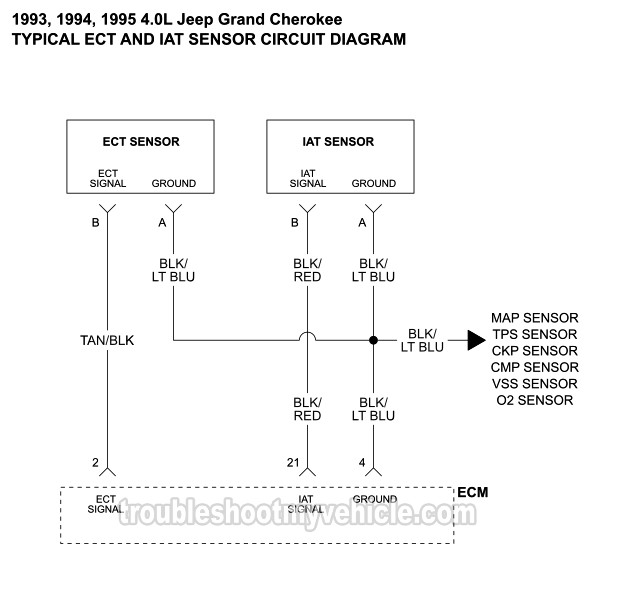
1993-1995 IAT And ECT Sensor Wiring Diagram (Jeep 4.0L)

1, 2, & 3 Wire Coolant Temperature Sensor Wiring Diagram

How to test coolant temp sensor connector | TDIClub Forums

Water Temperature Gauge - Jaeger - 1750GTV
Dash Instrument Testing - Falcon Enterprises
Wiring Instructions for Derale Temperature Gauge | etrailer.com
0 Response to "42 temperature gauge wiring diagram"
Post a Comment