41 refrigeration cycle ph diagram
PDF Ph diagram for refrigeration cycle Ph diagram for refrigeration cycle Efficiency - Working with the Refrigerant Circuit To measure what is happening the first thing to do is to find the temperatures and pressures at key points in the circuit. Measurement points for Temperature T and Pressure P can be used to define the process. PDF Refrigeration Cycle Tutorial - University of Oklahoma A "wet" cycle is shown in the next figure. 58 Figure 4:Wet refrigeration Cycle - The expander has been substituted by a throttling valve. If an expander had been used the line from dto awould be a vertical line. This is also done for mechanical reasons. The refrigeration cycles can also be represented in a P-H diagram.
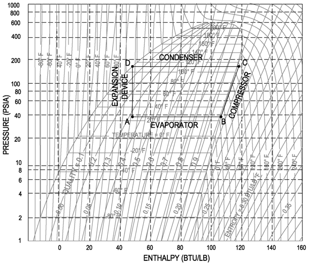
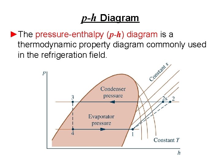
PDF Pressure-enthalpy Charts and Their Use - Rses Figure 4 is a pressure-enthalpy diagram of a typical refrigeration cycle in a system with one pound of HFC-134a. It uses (for this example) evaporating and condensing temperatures of 0°F and 120°F. Points on the diagram are labeled to correspond to locations of equipment in the system. Each step of the cycle can be approached separately.

Refrigeration cycle ph diagram
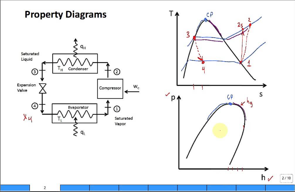
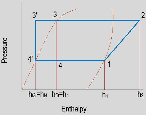
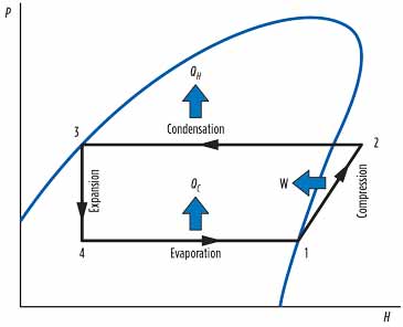
PDF Case 1: The Basics of Refrigeration Cycle P.H. Diagram ... Figure 1-6 Refrigeration Cycle P-H Diagram Image Figure 1-7 Properties of Refrigerant at -20℉ Figure 1-8 Properties of the Refrigerant at 105℉ H 1is the saturated suction of the compressor at -20ºF. at no losses. H 2is the compressor discharge point at no losses. H 5is the saturated liquid at 105ºF condensing temperature. PDF Thermodynamics of the refrigeration cycle gunt The refrigeration cycle in the log p-h diagram The distinctive feature of the refrigeration cycle is that it runs counter-clockwise, i.e. opposite to the joule or steam cycle. A change of state occurs when the refrigerant fl ows through one of the four main components of the refrigeration plant. The Heat exchanger - Wikipedia A heat exchanger is a system used to transfer heat between two or more fluids.Heat exchangers are used in both cooling and heating processes. The fluids may be separated by a solid wall to prevent mixing or they may be in direct contact. They are widely used in space heating, refrigeration, air conditioning, power stations, chemical plants, petrochemical plants, …
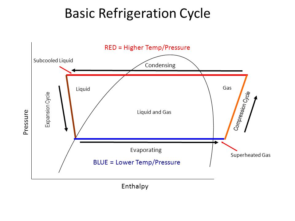
Refrigeration cycle ph diagram. PDF UNIT 2 REFRIGERATION CYCLE Refrigeration Cycle Refrigeration cycle is the basis of all refrigeration systems. So refrigeration cycle should be known to understand the refrigeration system. Some basic refrigeration cycles are discussed here through different diagrams. 2.2 VAPOUR COMPRESSION CYCLE Vapour compression cycle is an improved type of air refrigeration cycle in which a suitable ... PDF How does basic refrigeration cycle work? If you are interested in learning how a refrigeration system works, it is helpful to understand from the Ph (Pressure Enthalpy) chart perspective. It makes our life much easier. This is how the refrigeration cycle diagram looks: Yeah, it seems complicated at first, but it will be easier to understand once I have explained the refrigeration ... Chapter 9 Microbial Growth Flashcards | Quizlet Bacteria that grow in mine drainage at pH 1-2 are probably which of the following? A. alkaliphiles B. acidophiles C. neutrophiles D. obligate anaerobes. alkaliphiles. Bacteria isolated from Lake Natron, where the water pH is close to 10, are which of the following? A. alkaliphiles B. facultative anaerobes C. neutrophiles D. obligate anaerobes. a hot vent at pH 1.5. In which environment … Rankine Cycle - an overview | ScienceDirect Topics In this configuration, ORCs with upper cycle temperatures of about 300 °C have an efficiency of about 12.5% (Hassani and Price, 2001). The efficiency of the basic Rankine cycle can be increased by recuperation and reheating, which lead to efficiencies of 20.5% for the same boundary conditions (Hassani and Price, 2001). In this case, the ...
Super-Heat and the P&H Diagram - FUNDAMENTAL REFRIGERATION Super-Heat and the P&H Diagram. Adding more heat to a gas increases the temperature of the gas above its saturation temperature (the temperature in which it boiled into a gas). The temperature increase, or difference between the saturation temperature and the new temperature, is called super-heat. On the 410a cycle below, the refrigerant has ... Pressure-Enthalpy (P-h) diagram of: (a) an ideal ... Fig. 1 shows a typical refrigeration cycle with all components labelled in the correct sequence and position [5]. Technically, an ideal refrigeration cycle can best be illustrated with a... Maintenance Training Webinars | HD Supply Appliance. 3/23/2022 – Refrigerator, Part 2: The Defrost Cycle - 12 PM to 1 PM EST - Register For Webinar 3/23/2022 – Refrigerator, Part 2: The Defrost Cycle - 1:30 PM to 2:30 PM EST - Register For Webinar 3/23/2022 – Refrigerator Troubleshooting - 3 PM to 4 PM EST - Register For Webinar 4/7/2022 – Refrigerator, Part 1: The Cooling Cycle - 12 PM to 1 PM EST - … Refrigeration Basics and LNG - University of Oklahoma Figure 2-4: Wet refrigeration Cycle - The expander has been substituted by a throttling valve. If an expander had been used the line from d to a would be a vertical line. This is also done for mechanical reasons. The refrigeration cycles can also be represented in a P-H diagram. Figure 2-5: P-H diagram representation of a dry refrigeration cycle
Refrigeration - Cycle for Ideal conditions on a Pressure ... Learn how to draw a cycle for ideal conditions on a PH chart.Please provide feedback on this module by selecting "Like" or "Dislike". Your feedback and comme... Ideal vapour compression refrigeration cycle in p-h diagram Figure 1 shows the p-h diagram of a complete ideal vapour compression refrigeration system. Various calculations are done based on this system using different refrigerants. COP of vapour... PDF Refrigeration Cycle - Simon Fraser University M. Bahrami ENSC 461 (S 11) Refrigeration Cycle 3 Fig. 5-3: T-s and P-h diagrams for an ideal vapor-compression refrigeration cycle. 1-2: A reversible, adiabatic (isentropic) compression of the refrigerant. The saturated vapor at state 1 is superheated to state 2. wc =h2 − h1 Thermodynamics 1 Simulations - LearnChemE id = refrigeration-cycle-coefficient-of-performance (do not remove this text) Reversible and Irreversible Expansion or Compression Work Expansion or compression work for ideal gas in piston-cylinder system
2.1 The pressure-enthalpy diagram - SWEP
2.1 The pressure-enthalpy diagram - SWEP Refrigeration handbook 1. Basic heat transfer 2. Compression cycle 2.1 The pressure-enthalpy diagram; 2.2 Basic components; 2.3 The basic cycle in a log Ph diagram; 2.4 The complex cycle in a log Ph diagram; 2.5 Other components; 3. Compressors 4. Expansion valves 5. Refrigerants 6. Evaporators 7. Condensers 8.
P-H Diagram Thermodynamics | HVAC and Refrigeration PE Exam ...
Ideal refrigeration cycle P-h diagram; 1→2: isobaric ... Download scientific diagram | Ideal refrigeration cycle P-h diagram; 1→2: isobaric cooling and isothermal/isobaric condensation; 2→3: isenthalpic expansion; 3→4: isobaric/isothermal ...
Pressure-Enthalpy and the Variable Refrigerant Cycle - ppt ...
PDF Chapter - 2 - Industrial refrigeration systems (1) P-H Diagram Refrigeration Cycle Analysis. P-H Diagram is to analysis the feasibility of the refrigeration cycle, to calculate the thermodynamic properties of the refrigeration system. Use the P-H Diagram analysis, all the refrigerant flow rates and operating conditions at the design point for the system can be clearly determined.

Fault diagnosis of a vapor compression refrigeration system ...
Log ph diagram online I TLK Energy Representation of a refrigeration cycle. In our interactive log ph diagram, refrigeration cycles can be parameterized in different ways. For a simple refrigeration cycle, we offer the possibility to specify either the evaporating and condensing pressure or the evaporating and condensing temperature.

Efficiency - Measuring Refrigeration
PDF P-h Diagram -master Diagram of Refrigeration The main diagrams representing the refrigeration process are 1. Carnot Cycle (already covered in earlier text) 2. P-V diagram 3. T-S diagram (Temperature -Entropy diagram) 4. P-H- diagram (Pressure -Enthalpy diagram) 5. T-H-Diagram (Temperature -Enthalpy diagram)

REFRIGERANTS P-H DIAGRAM - Refrigeration - HVAC/R and Solar ...
CO2 Transcritical Systems Training Manual 042718 R22 P/H Diagram * Diagram created using REFPROP – NIST Reference Fluid Properties As can be seen, the critical point of R-22 is more than 200°F, placing it well above the operating conditions of typical refrigeration systems. This can be contrasted with the CO 2 PH diagram, with a critical point of 88°F.

Refrigeration cycle diagram explained - Refrigeration - HVAC ...
2.1 The pressure-enthalpy diagram - SWEP Refrigeration handbook 1. Basic heat transfer 2. Compression cycle 2.1 The pressure-enthalpy diagram; 2.2 Basic components; 2.3 The basic cycle in a log Ph diagram; 2.4 The complex cycle in a log Ph diagram; 2.5 Other components; 3. Compressors 4. Expansion valves 5. Refrigerants 6. Evaporators 7. Condensers 8. Practical advice

How a Water Source Heat Pump Works: Thermodynamics 101 ...
Refrigeration cycle diagram explained - Refrigeration ... Refrigeration cycle in the log p-h diagram Green = compressor Red = condenser Yellow = expansion valve Blue = evaporator 1 - 2 polytropic compression to the condensing pressure (for comparison 1 - 2' isentropic compression) 2 - 2'' isobaric cooling, deheating of the superheated vapour 2'' - 3' isobaric condensation
Solved A R134a mechanical refrigerator operating with the ...
PDF Refrigeration Cycle - Landmark University Fig. 11. T-S diagram for Wet Vapour Compression Cycle Fig. 12. P-h diagram for Wet Vapour Compression Cycle In this cycle, enthalpy at state 2 is found with the help of dryness fraction at this point (2). The dryness fraction at points 1 and 2 may be obtained by equating entropies at state 1 and 2. C.O.P = =

Refrigerant Ph Diagram - Heat Exchangers - Brewiki
2.3 The basic cycle in a log Ph diagram - SWEP 2.3 The basic cycle in a log Ph diagram Navigation Figure 2.8 shows the fundamental process that describes the ideal refrigeration cycle. The following are assumed for the fundamental process: No sub-cooling of the liquid or superheating of the gas Ideal compression, i.e. it occurs at constant entropy No pressure drop losses

2.1 The pressure-enthalpy diagram - SWEP
Rankine cycle - Wikipedia The regenerative Rankine cycle is so named because after emerging from the condenser (possibly as a subcooled liquid) the working fluid is heated by steam tapped from the hot portion of the cycle. On the diagram shown, the fluid at 2 is mixed with the fluid at 4 (both at the same pressure) to end up with the saturated liquid at 7.

2.4 The complex cycle in a log Ph diagram - SWEP
Explain vapour compression refrigeration cycle on T-S and ... the p-h and t-s diagram for the simple vapor compression refrigeration cycle is shown in the figure for vapour entering the compressor is in dry saturation condition the dry and saturated vapour entering the compressor at point 1 that vapour compresses isentropic ally from point 1 to 2 which increases the pressure from evaporator pressure to …

Category: Using Pressure Enthalpy Diagrams - FUNDAMENTAL ...
PLOTTING THE REFRIGERATION CYCLE Flashcards | Quizlet The first step in plotting a refrigeration cycle on a PH diagram is to establish the condensing and evaporating lines. Take the system operating pressures and convert them to absolute pressure by adding 15 These pressures will be used to establish the evaporator and condenser lines. (Pg 291)
Solved 5. Please refer to the P-h diagram on the following ...
2.1 The pressure-enthalpy diagram - SWEP Refrigeration handbook 1. Basic heat transfer 2. Compression cycle 2.1 The pressure-enthalpy diagram; 2.2 Basic components; 2.3 The basic cycle in a log Ph diagram; 2.4 The complex cycle in a log Ph diagram; 2.5 Other components; 3. Compressors 4. Expansion valves 5. Refrigerants 6. Evaporators 7. Condensers 8.
PRESSURE-ENTHALPY CHARTS AND THEIR USE INTRODUCTION The ...
The Refrigeration Cycle - In easy to understand ... In this final diagram of the refrigeration cycle we have introduced 3 new terms: Superheated, Saturated & subcooled. SUPERHEAT - Is an amount of heat added to refrigerant vapour beyond its boiling point. This ensures the refrigerant is in a gas state with no liquid present.
Case – 1 The Basics of Refrigeration Cycle P-H Diagram ...
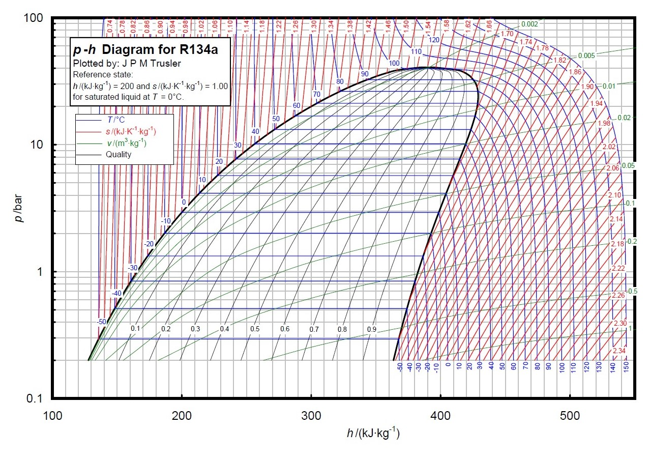
PDF P-h Chart for R134a (SI Units) - Syracuse University P-h Chart for R134a (SI Units) 1 Principles of Refrigeration MAE 554 Professor H. Ezzat Khalifa Syracuse University P-h Chart for R134a (SI Units) 2 Psychrometric Chart (ASHRAE) Psychrometric Processes Cool Heat Humidify Dehumidify Cool & Dehumidify Air Conditioning Systems Cool & Dehumidify Air 3 A/C System Psychrometric Processes

Efficiency - Measuring Refrigeration
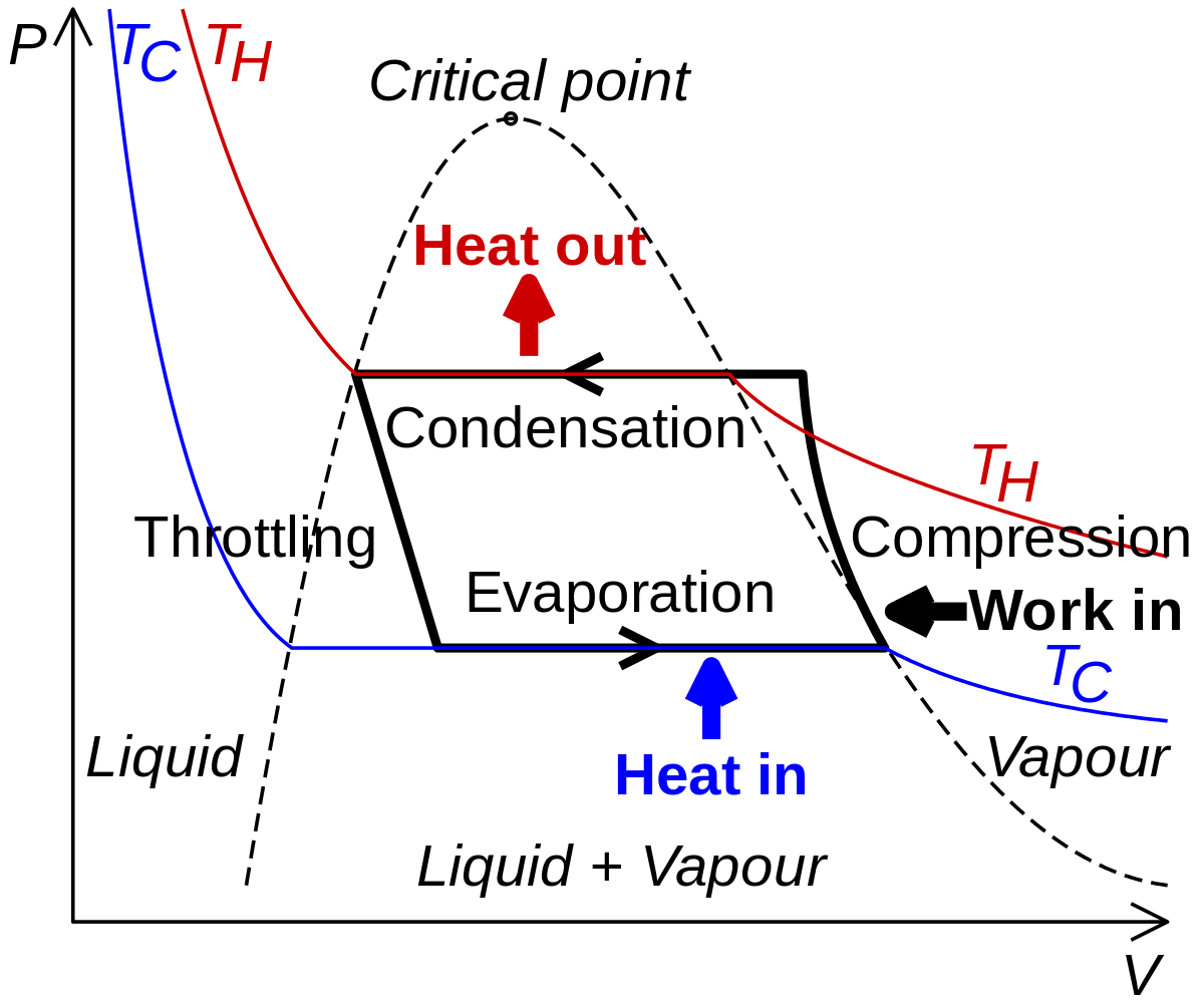
PDF Basic Knowledge Thermodynamics of the Refrigeration Cycle The log p-h diagram for refrigerant The refrigeration cycle For operating media which can have different phases, such as water or refrigerant, theT-sdiagram looks different. It has an area on the left (grey),in which the operating medium is liquid and supercooled. In the centre(blue) there is a mixture of steam and liquid, the wet steam.
PRESSURE-ENTHALPY CHARTS AND THEIR USE INTRODUCTION The ...
General Training Air Conditioning: Fundamentals - Carrier Module 10 – Refrigeration Cycle Accessories HVAC Training Objectives. Explain the differences between a basic cycle component and a cycle accessory; Using the diagram locate each cycle accessory at the appropriate location on the drawing; Explain how each of the accessories listed works and why they are necessary

Vapour compression refrigeration system on p-h diagram ...
2.4 The complex cycle in a log Ph diagram - SWEP Figure 2.9 The real refrigerant cycle in the log P/h diagram. The overheating is the difference between the temperatures at points 1.1 and 1.2. The sub-cooling is the difference between the temperatures at points 3.1 and 3.2. Figure 2.10 Log P/h diagram with temperature levels shown. Figure 2.11 The energy flow in a refrigerant system.

Refrigeration cycle diagram explained - Refrigeration - HVAC ...
plotting the refrigeration cycle Flashcards | Quizlet why is the condenser line wider than the evaporator line in a PH diagram of a refrigeration cycle. the condenser must get rid of the heat of the compressor as well as the heat gained in the evaporator. how can a PH diagram be used to determine the compression ratio.
Vapor-compression refrigeration - Wikipedia
gps-tracker-fuers-fahrrad.de Matsushita compressor model number
Refrigeration and Heat Pump Systems VaporCompression ...
What is Refrigeration Cycle? Basic, Diagram & Explanation ... The refrigeration cycle is a thermodynamic cycle to generate refrigerating effect with the use of an evaporator, compressor, condenser & expansion valve. This process is basically a thermodynamic process where working fluid absorbs heat from the surrounding at low temperature and reject the heat to the atmosphere at a higher temperature.

P-h diagram of the vapour-compression refrigeration cycle ...
Rankine cycle - Wikipedia The regenerative Rankine cycle is so named because after emerging from the condenser (possibly as a subcooled liquid) the working fluid is heated by steam tapped from the hot portion of the cycle. On the diagram shown, the fluid at 2 is mixed with the fluid at 4 (both at the same pressure) to end up with the saturated liquid at 7. This is ...
Property diagrams TS and PH for refrigeration
Heat exchanger - Wikipedia A heat exchanger is a system used to transfer heat between two or more fluids.Heat exchangers are used in both cooling and heating processes. The fluids may be separated by a solid wall to prevent mixing or they may be in direct contact. They are widely used in space heating, refrigeration, air conditioning, power stations, chemical plants, petrochemical plants, …
Design of Vapor-Compression Refrigeration Cycles
PDF Thermodynamics of the refrigeration cycle gunt The refrigeration cycle in the log p-h diagram The distinctive feature of the refrigeration cycle is that it runs counter-clockwise, i.e. opposite to the joule or steam cycle. A change of state occurs when the refrigerant fl ows through one of the four main components of the refrigeration plant. The

Thermodynamic scope for two-phase fluid networks - MATLAB
PDF Case 1: The Basics of Refrigeration Cycle P.H. Diagram ... Figure 1-6 Refrigeration Cycle P-H Diagram Image Figure 1-7 Properties of Refrigerant at -20℉ Figure 1-8 Properties of the Refrigerant at 105℉ H 1is the saturated suction of the compressor at -20ºF. at no losses. H 2is the compressor discharge point at no losses. H 5is the saturated liquid at 105ºF condensing temperature.

P-h diagram of vapor compression refrigeration cycle ...
Chapter – 2
JSRAE, Japanese Society for Refrigerating and AirConditioning ...

10 CHAPTER Refrigeration Cycles. - ppt video online download

Figure 1 from Energy performance of eco-friendly RE170 and ...

Energy efficiency improvements in refrigeration: Floating ...

vapour compression refrigeration cycle on p-h diagram ...

AC Working Principle Simple Explanation w/ Diagram
Pressure - Enthalpy Chart - Simple VCR System Questions and ...

Chapter 4c: First Law - Refrigerators (Updated 3/13/2013)

Heat pump and refrigeration cycle - Wikipedia
JSRAE, Japanese Society for Refrigerating and AirConditioning ...

Vapour Compression Refrigeration | Working with pv and Ts diagram | RAC | Sourav Kumar
Smart coolant for NGL processing in very hot regions
Processes | Free Full-Text | Performance Analysis and Working ...
0 Response to "41 refrigeration cycle ph diagram"
Post a Comment