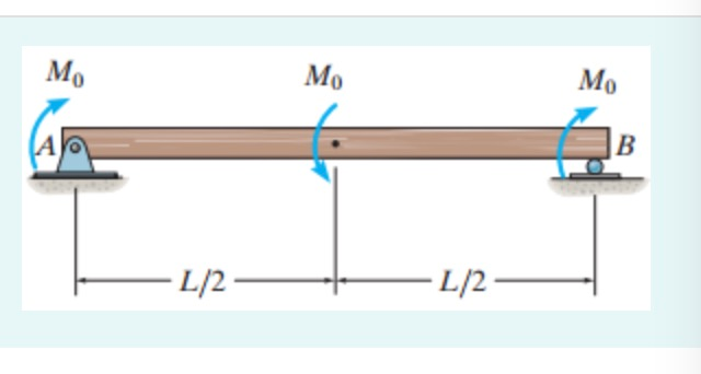
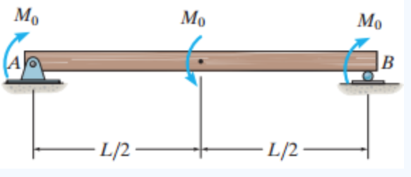
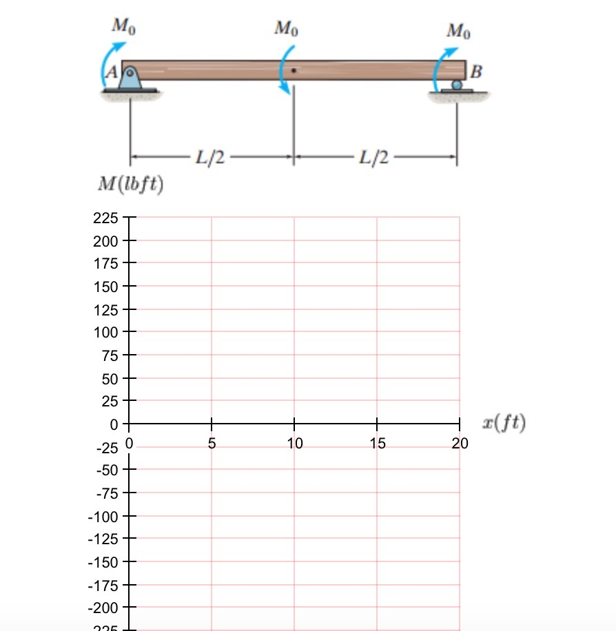
37 draw the shear diagram for the beam. assume that m0=200lb⋅ft, and l=20ft.
Academia.edu is a platform for academics to share research papers. Home › draw the shear and moment diagram for the beam › draw the shear diagram for the beam › draw the shear diagram for the beam. 7.78 › draw the shear diagram for the beam. assume that m0=200 lb⋅ft and l=20ft › draw the shear diagram for the beam. assume that w0=10kip/ft and l=18ft › draw the shear diagram for the beam. follow the sign convention › draw the shear diagram for ...
Search: Determine The Moment Of The 200 Lb Force About Point A And About Point O

Draw the shear diagram for the beam. assume that m0=200lb⋅ft, and l=20ft.
Draw the shear diagram for the beam. Assume that w 0 | Chegg.com. Engineering. Mechanical Engineering. Mechanical Engineering questions and answers. Draw the shear diagram for the beam. Assume that w 0 =10kip/ft , and L=18ft Draw the moment diagram for the. Question: Draw the shear diagram for the beam. Assume that w 0 =10kip/ft , and L=18ft ... Yeah, I'm gluing up stock. For the prototype I made the rear side panel (18" tall, 8" wide) from 2-3 boards and the fore side panel (9" tall, 8" wide) from 2-3 boards. After making the steps and dovetailing them to their side panels (but not gluing), I glued the rear side panel to the front side panel to make the whole "L" shaped side. plans for kamado grill table May 31, 2020 - Get access to 50 step-by-step woodworking plans Download ... Simply enter your email below #wood #woodworking @working #plan #video ...
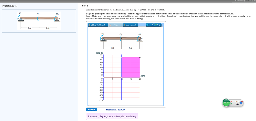
Draw the shear diagram for the beam. assume that m0=200lb⋅ft, and l=20ft.. Draw the shear diagram for the beam. Assume that M0=200lb⋅ft, and L=20ft. Begin by placing the lines of discontinuity. Place the appropriate function between the lines of discontinuity, ensuring the endpoints have the correct values. Note - Make sure you place only one vertical line at places that require a vertical line. If you. Draw the shear and moment diagrams for the beam and determine the shear and moment as functions of x. 3 m 3 m x AB 200 N/m 400 N/m Ans: M = e - 100 9 x ... the web D of the beam. 15 kip # ft. 3 in. 5 in. 1 in. 1 in. 8 in. M 15 kip ft 1 in. A B D Using flexure formula % of moment carried by web = Ans. 3.3852 15 makelegstable 🙅York Saw And Knife. I built a door frame that was about 1/4″ smaller in both dimensions than the opening for it. So, the opening here was 22 1/2″ wide and 23″ tall, so I made the door 22 1/4″ x 22 3/4″. Write shear and moment equations for the beams in the following problems. In each problem, let x be the distance measured from left end of the beam. Also, draw shear and moment diagrams, specifying values at all change of loading positions and at points of zero shear. Neglect the mass of the beam in each problem.
Civil Engineering questions and answers. Draw the shear diagram for the beam Assume that M = 200 Ib. middot ft, and L = 20 ft. Begin by placing the lines of discontinuity. Place the appropriate function between the lines of discontinuity, ensuring the endpoints have the correct values. Problem 4.3-3 Determine the shear force V and bending moment M at the midpoint of the beam with overhangs (see figure). Note that one load acts downward and the other upward. Solution 4.3-3 Beam with overhangs 260 CHAPTER 4 Shear Forces and Bending Moments P P b L b P ¢1 2b L ≤ (upward) R A 1 L [P(L b b)] ©M B 0 Free-body diagram(C is the ... - Attach the top to the cabinet carcass with L brackets as shown in the picture below. This will make for easy removal.. just in case. Put the L brackets in any area that the top may try to rise up a little. I used 4 L brackets. Install the TV per the Firgelli manual: - Lay the TV down on a flat rug and install the 4 brackets to the TV. Slide ... Publishing platform for digital magazines, interactive publications and online catalogs. Convert documents to beautiful publications and share them worldwide. Title: Dynamics 11th edition, Author: cireneulucio, Length: 844 pages, Published: 2010-07-07
Draw the shear diagram for the beam. Assume that M0=200lb⋅ft, and L=20ft. Begin by placing the lines of discontinuity. Place the appropriate function between the lines of discontinuity, ensuring the endpoints have the correct values. Note - Make sure you place only one vertical line at places that require a vertical line. 4.3 Shear- Moment Equations and Shear-Moment Diagrams The determination of the internal force system acting at a given section of a beam : draw a free-body diagram that expose these forces and then compute the forces using equilibrium equations. The goal of the beam analysis -determine the shear force V and Search: Determine The Moment Of The 200 Lb Force About Point A And About Point O Search: Determine The Moment Of The 200 Lb Force About Point A And About Point O
Zkkwh29lbmsu2m
Knowing that for each cable TA = 3100 N and TB = 3300 N, determine (a) the angular acceleration of the roll, (b) the acceleration of its mass center. SOLUTION Data: m = 1200 kg I = mk 2 = (1200) (0.150) 2 = 27 kg ⋅ m 2 1 1 r = d = (0.100) = 0.050 m 2 2 TA = 3100 N TB = 3300 N (a) Angular acceleration.
Solved Draw The Shear Diagram For The Beam Assume That Chegg Com
Three conversion factors are needed: m one to cancel GPa and kN; a second to cancel mm2 and m2; and a third to put the final answer in mm. 12 fChapter 1: Introduction to Strength of Materials Example #6 The weight of a solid object is the specific weight of the material times the volume of the object: W = γV .

Drawing Shear And Moment Diagrams For Beam Youtube
Draw the shear diagram for the beam. Assume that wo 10 kip/ft, and L 18 ft Begin by placing the lines of discontinuity. Place the appropriate function between the lines of discontinuity, ensuring the endpoints have the correct values. U reset help add vertical line off delete add segment v V (ki 600 40 20 x (ft) 14 16 1 20 -40 60 -80 100
2
Check out http://www.engineer4free.com/structural-analysis for more free structural analysis tutorials. The course covers shear force and bending moment diag...

Pdf Problem 7 1 Ghabriel Barbieri Molinarolli Academia Edu
draw free-body diagrams of bolt HJ and of the portion of the bolt located between the two planes (Fig. 1.19). Observing that the shear P in each of the sections is P = F∕2, the average shearing stress is τave = P F∕2 F = = A A 2A (1.10) H FC F K P K' L F L' P FD J (a) (b) Fig. 1.19 (a) Diagram of bolt in double shear;
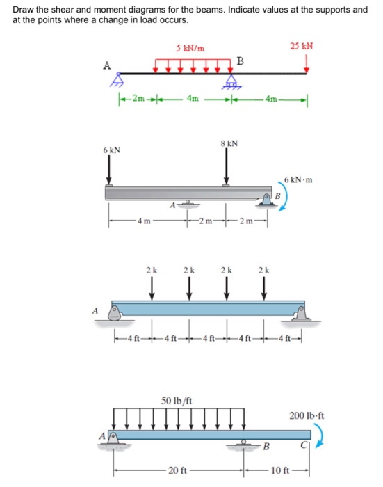
Solved Draw The Shear And Moment Diagrams For The Beams Chegg Com
1. A domesticated carnivorous mammal (Canis familiaris syn. Canis lupus subsp. familiaris) occurring as a wide variety of breeds, many of which are traditionally used for hunting, herding, drawing sleds, and other tasks, and are kept as pets.

Hibbeler Statics 11 Ed Instructor Solution Manual Wordpress Com Moam Info
Academia.edu is a platform for academics to share research papers.
Solved Draw The Shear Diagram For The Beam Assume That Chegg Com
Aviation History magazine is an authoritative, in-depth history of world aviation from its origins to the Space Age. Aviation History offers air enthusiasts the most detailed coverage of the history of manned flight, with action-packed stories and illustrations that put the reader in the cockpit with pilots and military (Army, Navy, and Marines) aviators to experience aviation's greatest dramas.

Please Answer This Question In One Hour Problem 6 13 Part A Draw The Shear Diagram For Homeworklib
But, I assume that the camp best fitted to the wants of the average outer is the one that combines the essentials of dryness, lightness, portability, cheapness, and is easily and quickly put up. Another essential is, that it must admit of a bright fire in front by night or day.

Pdf Mechanics Of Materials By Andrew Paytel Khan Mohammad A B D U L Kader Academia Edu
flooringdiyinexpensive 🙅Make a Better {DEWALT® SDS MAX High Impact Carbide and SDS Plus 2 Cutter Masonry Drill bits are covered by the manufacturer's NO BREAK GUARANTEE.. If your drill bit fails for any reason while the anchor wear mark is still visible on the product, DEWALT will replace it free of charge.
2
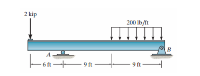
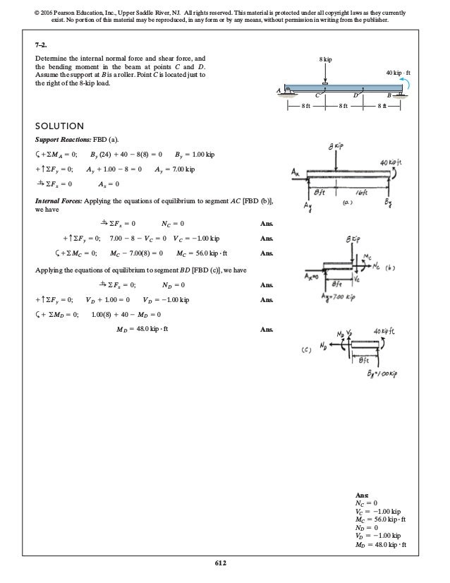
Determine the internal normal force, shear force, 300 lb/ft and moment acting at point C and at point D, which is 200 lb/ft 200 lb/ft located just to the right of the roller support at B. D F E A C B 4 ft 4 ft 4 ft 4 ft *7-16.
Solved Draw The Shear Diagram For The Beam Draw The Chegg Com
Draw the shear diagram for the beam. Assume that M 0=200lb⋅ft, and L =20ft. Show transcribed image text. Expert Answer. Who are the experts? Experts are tested by Chegg as specialists in their subject area. We review their content and use your feedback to keep the quality high. 100% (4 ratings)
2
3 PROPRIETARY MATERIAL. © 2010 The McGraw-Hill Companies, Inc.All rights reserved. No part of this Manual may be displayed, reproduced or distributed in any form or ...
2
Transcribed image text: Problem 6.13 Part A Draw the shear diagram for the beam. Assume that Mo 200 lb.ft, and L 20 ft. Begin by placing the lines of discontinuity. Place the appropriate function between the lines of discontinuity, ensuring the endpoints have the correct values Note Make sure you place only one vertical line at places that require a vertical line.
2
plans for kamado grill table May 31, 2020 - Get access to 50 step-by-step woodworking plans Download ... Simply enter your email below #wood #woodworking @working #plan #video ...
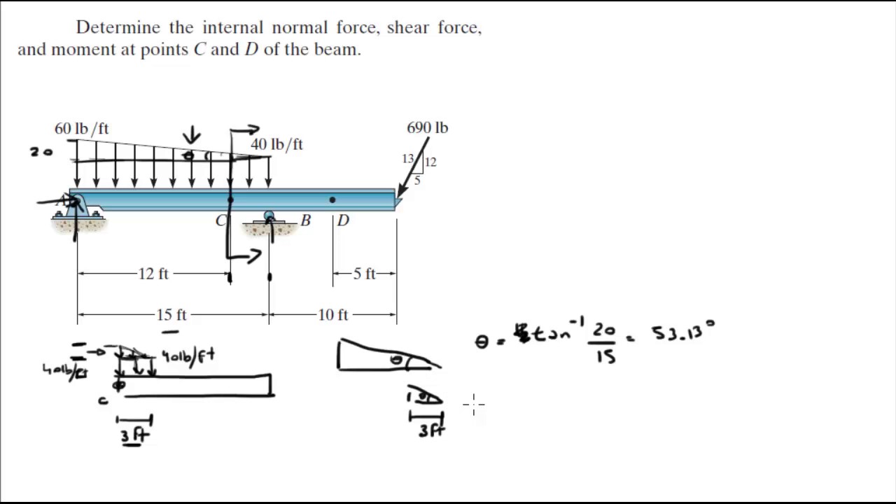
Determine The Internal Normal Force Shear Force And Moment At Points C And D Of The Beam Youtube
Yeah, I'm gluing up stock. For the prototype I made the rear side panel (18" tall, 8" wide) from 2-3 boards and the fore side panel (9" tall, 8" wide) from 2-3 boards. After making the steps and dovetailing them to their side panels (but not gluing), I glued the rear side panel to the front side panel to make the whole "L" shaped side.
2
Draw the shear diagram for the beam. Assume that w 0 | Chegg.com. Engineering. Mechanical Engineering. Mechanical Engineering questions and answers. Draw the shear diagram for the beam. Assume that w 0 =10kip/ft , and L=18ft Draw the moment diagram for the. Question: Draw the shear diagram for the beam. Assume that w 0 =10kip/ft , and L=18ft ...
2
Ch06 07 Pure Bending Amp Transverse Shear

Draw Shear And Moment Diagrams For The Beam 50 Lb Ft 200 Lb Ft Ao B 20 Ft Homeworklib

Giancoli 7th Edition Chapter 9 Problem 16 Giancoli Answers
Engineering Mechanics Statics 7th Edition J L Meriam L G Kraige Pdf Pdfcoffee Com

Engineering Mechanics Statics 7th Edition J L Meriam L G Id 5d02b294e9d6f

Mechanics Of Materials Pages 201 250 Flip Pdf Download Fliphtml5

Solved Consider The Beam Shown In The Figure Below Determine The Shear 1 Answer Transtutors
2
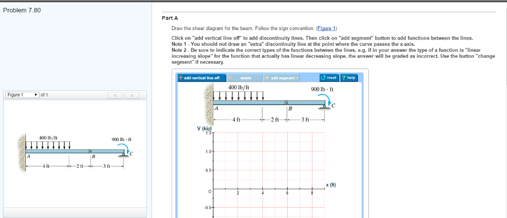
Solved Problem 7 80 Figure 1 Of 1 400 Lb Ft 4 Ft 2 Ft 900 Chegg Com
2
Chapter 7

Pdf Duiuyioupoipo Tachibana Aki Academia Edu
Solved Draw The Shear Diagram For The Beam Assume That Chegg Com
2
Solved Problem 6 13 Part A Draw The Shear Diagram For The Chegg Com

Vector Mechanics For Engineers Chapter 07 Pdf Pdfcoffee Com

Pdf Problem 2 1 Adian Sixx Academia Edu

Mechanics Of Materials By Andrew Paytel Pdf Bending Stress Mechanics
2
0 Response to "37 draw the shear diagram for the beam. assume that m0=200lb⋅ft, and l=20ft."
Post a Comment