37 fluorescence energy level diagram
Fluorescence is the emission of light by a substance that has absorbed light or other electromagnetic radiation.It is a form of luminescence.In most cases, the emitted light has a longer wavelength, and therefore a lower photon energy, than the absorbed radiation. A perceptible example of fluorescence occurs when the absorbed radiation is in the ultraviolet region of the spectrum (invisible to ... • an energy level diagram shows four types of scattering processes • Rayleigh scatter is due to microscopic refractive index changes, while Raman scatter is due to time-dependent changes in polarizability • scattering cross-sections are used to compare signal strengths from Rayleigh, Raman and fluorescence
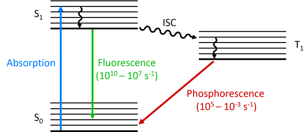
Fluorescence differs from phosphorescence in that the electronic energy transition that is responsible for fluorescence does not change in electron spin, which results in short-live electrons (<10-5 s) in the excited state of fluorescence. In phosphorescence, there is a change in electron spin, which results in a longer lifetime of the excited ...
Fluorescence energy level diagram
Jean Perrin was likely the first person to use a molecular energy level diagram to illustrate the absorption and emission of light, which he used to explain the concept of thermally activated delayed fluorescence by introducing a 'metastable state'. 4 This model and diagram was then explained in greater detail in Francis Perrin's doctoral ... Schematic energy-level diagram Jablonski diagram of the energy states related to the LIF spectroscopy for a solution mixture of PH and an intermediate product Q. Levels 0, 1, and 2 correspond to ... Energy Levels in Fluorescence The first step in any light emitting process is to give electrons in the lowest energy states enough energy to change to a higher energy level (Figure 3). In a solid with an impurity band the electrons in the conduction band do not necessarily lose all their energy at once and return directly to the ground state.
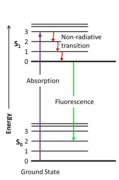
Fluorescence energy level diagram. Energy levels, electronic/vibrational, Jablonski diagram FIG. 2. Correlation between absorption, fluorescence, and phosphorescence spectra and the electronic and vibrational energy levels in the term diagram (called Jablonski term scheme) absorption (A), fluorescence (F), and phosphorescence (P) spectra. Just as above, we can derive expressions for any fluorescence lifetime for any number of ... Energy-level diagram for typical photoluminescent system • Fluorescence: absorption of photon, short-lived excited state (singlet), emission of photon. Jablonski diagram for fluorescence. An excited-state electron rapidly (on the order of 10 -12 seconds) loses its energy to vibration (heat), a process called internal conversion, and falls to the lowest level of the first (S 1) excited state. From there the electron may fall to one of the sub-levels of the ground (S 0) state, emitting a photon ... The energy level diagram is essentially the absorption spectrum converted to an energy scale and then tilted by 90 degrees, with the molecular energy levels shown as bands (series of parallel horizontal lines). What happens to the excess energy after a molecule absorbs light? Fluorescence results from the first, lowest energy excited state.
Interpretation of the Energy Diagram • Absorption : Ground state to Excited state •(10-15 sec) • Relaxation: Excited state to Ground state –Internal Conversion (IC) •nonradiative (thermal, collisional) relaxation of electrons through vibrational states (10-12-- 10 14 sec) –Emission •fluorescence (spontaneous emission: 10-10 - 10-8 sec) 4. Fluorescence 5. Intersystem Crossing 6. Time Scale 7. Outside Links 8. Contributors Introduction A Jablonski diagram is basically an energy diagram, arranged with energy on a vertical axis. The energy levels can be quantitatively denoted, but most of these diagrams use energy Figure 1-5: Fluorescence, shown in this Jablonski diagram, involves emitting a photon at a lower energy than the photon that was initially absorbed. The diagram is read from left to right – absorbance occurs first, then vibrational relaxation, then fluorescence. Download scientific diagram | Energy Level Diagram for Fluorescence of Ruby [14] from publication: Synthesis and high-pressure structural studies of AuX 2 (X = Al, Ga, In) compounds | Three ...
that can shift the electron into a higher energy level. The range of wavelengths able to induce fluorescence in this manner is directly related to the excitation spectrum of a fluorophore (Figure 2, bottom). Figure 2 The fundamental physics of fluorescence. Top. Jablonski diagram Energy-level diagram of two chromophores: G and S1 indicate the ground and first excited states respectively (heavy lines). Thevibrational levels are the thin lines. A. This molecule is capable of fluorescing by the transition (solid arrow) indicated in the diagram. ... Fluorescence Quantum Yield = Q =(no. of molecules fluorescing) / (no. of ... Schematic diagram of the excited state proton transfer from dye molecules to the titania surface, fluorescence process and energy level diagram (IMAGE) Shinshu University. Several investigators reported luminescence phenomena during the seventeenth and eighteenth centuries, but it was British scientist Sir George G. Stokes who first described fluorescence in 1852 and was responsible for coining the term in honor of the blue-white fluorescent mineral fluorite (fluorspar). Stokes also discovered the wavelength shift to longer values in emission spectra that bears his name. Fluorescence was first encountered in optical microscopy during the early part of the twentieth century by several notable scientists, including August Köhler and Carl Reichert, who initially reported that fluorescence was a nuisance in ultraviolet microscopy. The first fluorescence microscopes were developed between 1911 and 1913 by German physicists Otto Heimstädt and Heinrich Lehmann as a spin-off from the ultraviolet instrument. These microscopes were employed to observe autofluorescence in bacteria, animal, and plant tissues. Shortly thereafter, Stanislav Von Provazek launched a new era when he used fluore
Chemiluminescence vs Fluorescence
same energy. From there the molecules again lose energy until the lowest vibrational level of the first excited state is reached. From this level, the molecule can return to any of the vibrational levels of the ground state, emitting its energy in the form of fluorescence. If this process takes
Jablonski diagram / Perrrin-jablonski diagram - YouTube
to exactly transition from the ground state to the lowest energy level of S 1, the molecule will also undergo a change in vibration, rotation and/or move into an even higher electronic orbital (S 2). Thus, there is a range of wavelengths that can excite a molecule. The minimum ener-gy required for fluorescence, however, is from a photon that ...
Chemical Education Journal(CEJ), Vol.13, No.2/Registration No.13-22
A typical Jablonski diagram illustrates the singlet ground state (S(0)), in addition to the first (S(1)) and second (S(2)) excited singlet states as a stack of horizontal lines.In the tutorial, the thicker lines represent electronic energy levels, while the thinner lines denote the various vibrational energy states (rotational energy states are ignored).

(a) Energy level diagram for Raman scattering and ...
Summary of fluorescence process. The cyclical fluorescence process can be summarized as: Step 1. Excitation of a fluorophore through the absorption of light energy. Step 2. A transient excited lifetime with some loss of energy. Step 3. Return of the fluorophore to its ground state, accompanied by the emission of light.
University of Manitoba - Information Services and Technology - Optical Imaging Overview
Fluorescence Spectroscopy Molecular Energy Levels and Absorption Spectra The phenomenon of fluorescence is intimately linked with that of absorption by molecules of energy in the form of photons of visible (or ultraviolet) light. To understand the phenomenon of fluorescence, we must thus first understand the process of light absorption.
What is the Jablonski Diagram?
ADVERTISEMENTS: Read this article to learn about the principles of fluorescence. Fluorochromes and Light: Fluorochromes are essentially dyes, which accept light energy (e.g., from a laser) at a given wavelength and re-emit it at a longer wavelength. These two processes are called excitation and emission. The process of emission follows extremely rapidly, commonly in the […]

Absorption and Fluorescence | PSL
Basic Principles of Fluorescence Spectroscopy 1.1 Absorption and Emission of Light As fluorophores play the central role in fluorescence spectroscopy and imaging we ... quantum mechanical assembly of one-electron energy levels appropriate to the particle in the box model. In this case, one considers the potential energy of the ...

sunflower field
Fluorescence: High-energy radiation (such as ultraviolet or X-ray) is captured by electrons circling an atom and re-emitted as light energy, resulting in fluorescence. Phosphorescence: Phosphorescence is light energy emitted by a certain form of chemical reaction in which the reactants' excess chemical energy is released as light energy. Q2.
Fluorophores Fluorophores
Perrin-Jablonski diagram: 7 ... low vibrational energy levels of S n.This overlap makes transition between states highly probable. Internal conversion is a transition occurring between states of the same multiplicity and it takes place at a time scale of 10 -¹² (faster than that of fluorescence process). The energy gap between S ₁ and S ₀ ...
Fluorescence - Chemistry LibreTexts
The Jablonski Diagram is named after Polish physicist Aleksander Jabłoński who, due to his many pioneering contributions, is regarded as the father of fluorescence spectroscopy.1 He received his doctorate for the work “On the influence of the change of wavelengths of excitation light on the fluorescence spectra” where he provided experimental proof that the fluorescence spectrum is independent to the wavelength of the excitation light. Some of his most notable contributions to fluorescence spectroscopy were furthering the understanding of the theory of fluorescence polarisation in solutions; the concept of concentration quenching; and the development of the famous diagram which now bears his name to explain the spectra and kinetics of fluorescence, delayed fluorescence and phosphorescence.1 However, the diagram is more correctly called a Perrin-Jablonski diagram to recognise the important contributions in its development by French physicists Jean Baptist Perrin, winner of the 1926 N...

Energy Level Diagram
Fluorescence is generally studied with highly conjugated polycyclic aromatic molecules that exist at any one of several energy levels in the ground state, each associated with a specific arrangement of electronic molecular orbitals. The electronic state of a molecule determines the distribution of negative charge and the overall molecular geometry.
Fluorescence – how it works
our calculations as we will be looking at the difference between energy levels. In the diagram we can see that a photon is absorbed by an electron and that it transitions from the ground state to a higher (less negative) energy level. (2)! Work out the energy difference (ΔE) between these two energy levels (n=1, and n=4) in eV. -0.85-(-13.6 ...

(PDF) Fluorescence Spectroscopy and Chemometric Modeling ...
To operate the tutorial, first select an absorption and emission mechanism (Fluorescence, Phosphorescence, or Delayed fluorescence) by toggling through the choices presented in the pull-down menu. Next, click on the Start button with the mouse to induce a virtual electron to absorb energy and be promoted to a higher energy level. After the electron arrives at the higher energy level, it will then decay in a manner typical of the selected excitation mechanism. The approximate lifetimes of electronic transitions appear in the tutorial window while each transition is occurring.

Mobile Delousing Unit, Truck Equipment, Plan of Operation and Erection Procedure, Presentation Drawing (1943) // Bertrand Goldberg American, 1913-1997
Energy Levels in Fluorescence The first step in any light emitting process is to give electrons in the lowest energy states enough energy to change to a higher energy level (Figure 3). In a solid with an impurity band the electrons in the conduction band do not necessarily lose all their energy at once and return directly to the ground state.

Scheme of Single-molecule fluorescence. (A) An energy ...
Schematic energy-level diagram Jablonski diagram of the energy states related to the LIF spectroscopy for a solution mixture of PH and an intermediate product Q. Levels 0, 1, and 2 correspond to ...

untitled (1969) // Dan Flavin American, 1933–1996
Jean Perrin was likely the first person to use a molecular energy level diagram to illustrate the absorption and emission of light, which he used to explain the concept of thermally activated delayed fluorescence by introducing a 'metastable state'. 4 This model and diagram was then explained in greater detail in Francis Perrin's doctoral ...

Energy level diagrams

(a) Energy level diagram for Raman scattering and ...

silhouette of personr
Fluorescence, Phosphorescence, Photoluminescence Differences
3PF Microscopy

wind turbines on snowy mountain under clear blue sky during daytime

(a) Energy level diagram for Raman scattering and ...

(a) Erbium ytterbium energy level diagram. (b) Example ...

Energy level diagrams describing two-photon fluorescence ...

Untitled (Auditorium Building, Street Level) (1953/55, printed 1973) // Richard Nickel (American, 1928–1972) printed by Patrice Grimbert (French, 1947–1974)

Fluorescent/Phosphorescent Dopants

Two-photon excited fluorescence versus SHG. Displayed are ...
Fluorescence

5 Jablonski energy level diagram showing the various decay ...

black solar panel under red and gray clouds

Monochrome, National Trust, Coastal Landscape, Isle Of Staffa, Argyll & Bute, Scotland.

(a) Energy level diagram for Raman scattering and ...

Marina City, Chicago, Illinois, Bridge Level Site Plan (1961–62) // Bertrand Goldberg American, 1913-1997

River City II: Geometry Study (n.d.) // Bertrand Goldberg American, 1913-1997
Fluorescent Probes | Thermo Fisher Scientific - DE

River City, Aerial Perspective (1979) // Bertrand Goldberg American, 1913–1997
0 Response to "37 fluorescence energy level diagram"
Post a Comment