39 fe cr phase diagram
@article{osti_7218909, title = {Phase diagram of Fe--Cr--Co permanent magnet system}, author = {Kaneko, H and Homma, M and Nakamura, K and Ikada, M and Thomas, G}, abstractNote = {The miscibility gap of the ..cap alpha.. phase in Fe-Cr-Co permanent magnet alloys is constructed using mechanical hardness and Curie temperature measurements. . It is found that the miscibility gap of the Fe-Cr ... the ternary phase diagram with respect to the aus-tenite stabilized region in the low Cr composition has not beenentirely identified evenin the recent st.udy. Thepurpose of this study is to investigate the eq,ui-librium phasediagram of Fe-Cr-Mnsystem at 923 K (650'C), in particular, to examine the extent of a single phase reg_ion in the low Cr ...
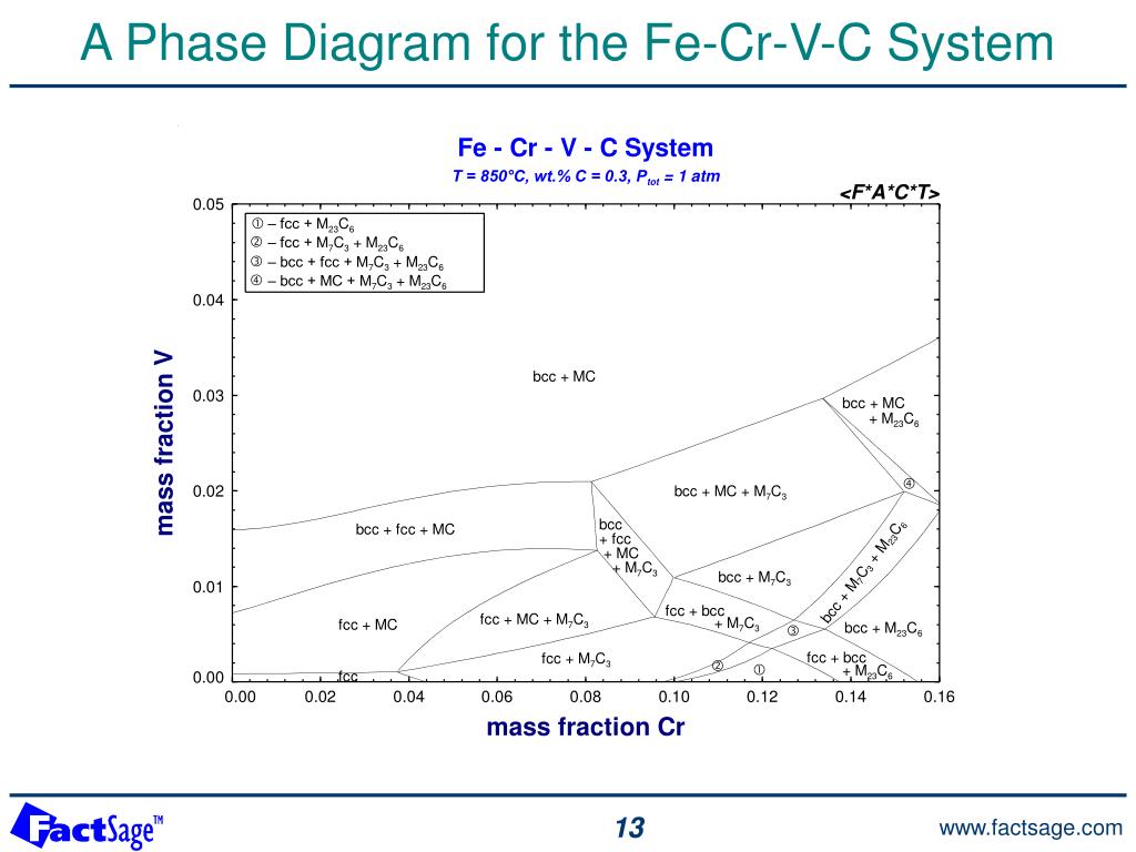
It is evident from Figure 6 (Fe-Cr-C phase diagram) that typical martensitic steels should exhibit ferrite and M 23 C 6 in equilibrium at for example, 600°C. In practice, this carbide is only found after relatively long ageing. because it is preceded by Intermediate phases in the sequence cementite, M 2 X and M 7 C 3 , leading finally to M 23 ...
Fe cr phase diagram
Cr Si Mn W Mo Review Fe-C phase diagram • 2 important points-Eutectoid (B): γ⇒α+Fe 3C-Eutectic (A): L ⇒γ+Fe 3C Fe 3 C (cementite) 1600 1400 1200 1000 800 600 400 0 12 3 4 5 66.7 L γ (austenite) γ+L γ+Fe 3C α+Fe 3C α + γ L+Fe 3C δ (Fe) C o, wt% C 1148°C T(°C) α 727°C = Teutectoid A R S 4.30 Result: Pearlite = alternating ... The Fe-Cr-Mo ternary phase diagram is very significant to steel research and design since both Cr and Mo are key alloying elements of many steel compositions, especially stainless steels. Most steels are used at or below the intermediate temperatures (about 600-900 C for Fe-Cr-Mo), thus phase diagrams at these temperature ranges are by SM Dubiel · 2011 · Cited by 49 — The “official” phase diagram of the Fe-Cr alloy system showing, in particular, the borders of the σ-phase occurrence is presented in Fig. 2.1.
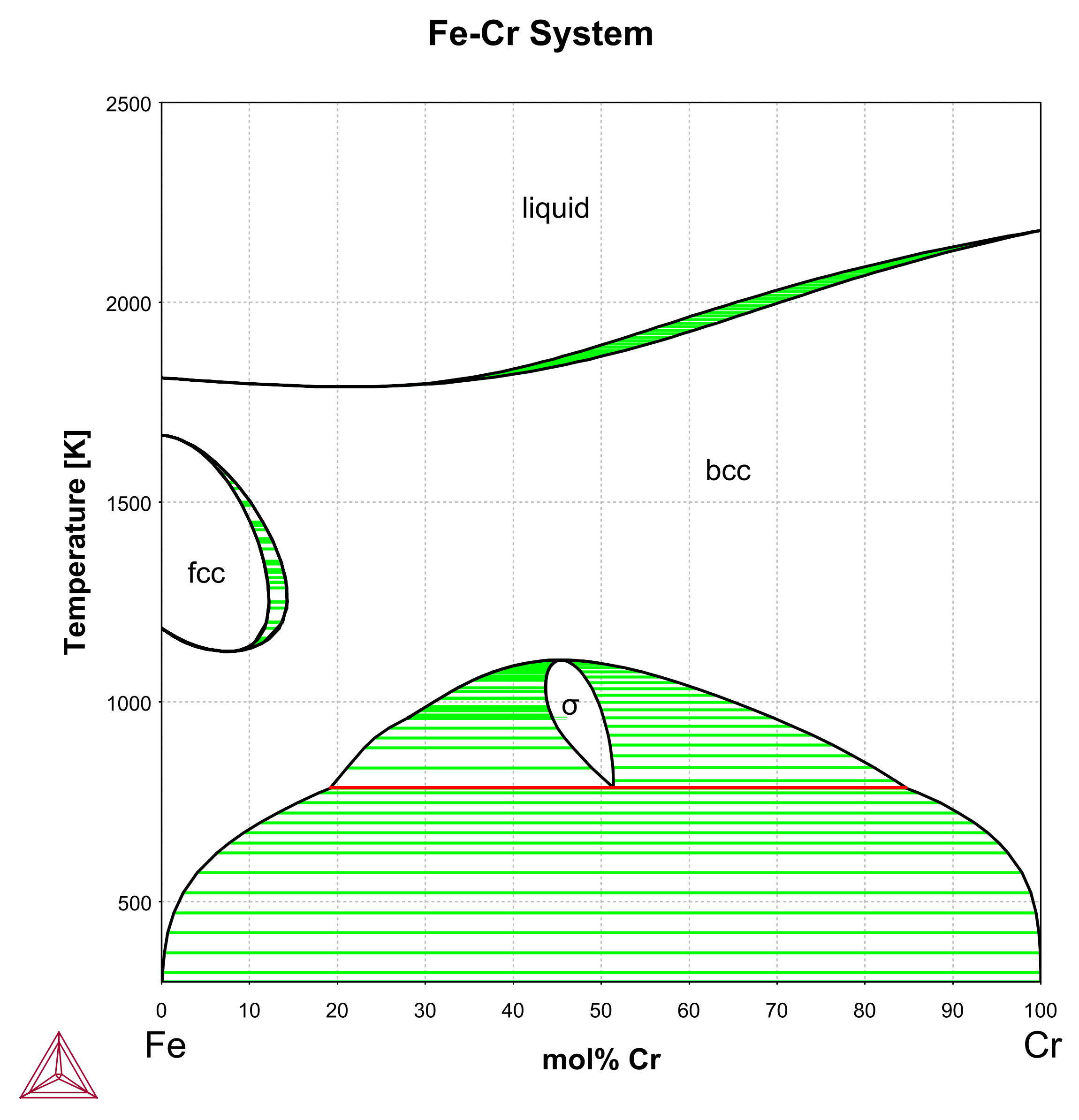
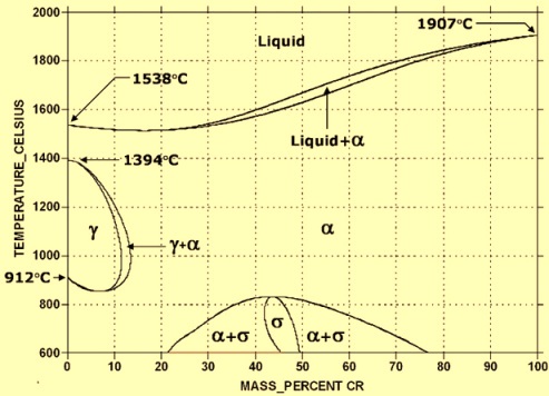
Fe cr phase diagram. by S Cao · 2016 · Cited by 17 — [5] The Fe-Cr-Mo phase diagram contains two solid solutions (bcc (α) and fcc (γ)), four binary intermetallic compounds/phases (the σ, μ, λ (the ... the phase diagram calculations of Fe-Cr-Al alloy, the irregular tetra-hedron (IT) cluster approximation [41] which is commonly used in literature [39,40,60] is adopted. Fig. 1 is the IT cluster and the four vertices of an IT cluster are labeled by i,,,jkl for convenience. The The phase diagram of the Fe-Cr binary system is at Fig 1. The melting point of Fe and Cr is taken at the pressure of 1 atmosphere as 1538 deg C and 1907 deg C respectively. The sigma phase, which is an intermetallic FeCr compound, can sometimes form in Fe-Cr alloys, such as AISI 316 or AISI 310 stainless steels. Download scientific diagram | The binary Fe-Cr phase diagram [17]. from publication: Powder metallurgy of stainless steel: State-of-the art, challenges, ...
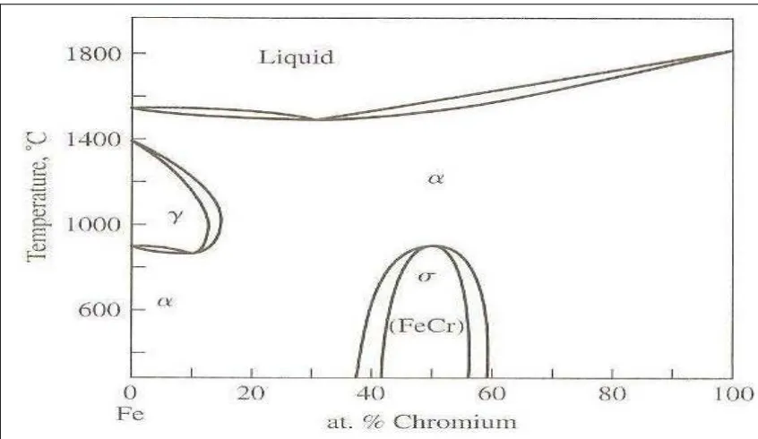
26 Feb 2018 — Fe-Cr phase diagram shows which phases are to be expected at equilibrium for different combinations of chromium content and temperature. Publication detail. Home. Rate this publication. Phase diagrams for FE-CR-NI based alloys. Part 1: Phase diagrams for binary and ternary alloys of FE, CR and NI with C and with SI. EU publications. Download Order. 3) Isothermal phase diagram of Fe-Cr-O system at 1 600°C was established. The relationshp between the chromium content of Fe-Cr melt and the oxide phase equilibrated was determined. below 1% Cr-cubic chromite, 1-7%Cr-c/a=1-0.95 above 7% Cr-Cr 2 O 3 2.1. σ phase in the Fe-Cr system2.1.1. Phase stability of σ phase. The σ phase was discovered for the first time in 1907 in the Fe-Cr system. It is nowadays known to be present in more than forty binary systems .In the Fe-Cr system, the σ phase is stable from ~44 to ~50 at% Cr .It is formed by a congruent reaction BCC ↔ σ at temperatures between 1093 and 1098 K , and decomposes by a ...
by SM Dubiel · 2011 · Cited by 49 — The “official” phase diagram of the Fe-Cr alloy system showing, in particular, the borders of the σ-phase occurrence is presented in Fig. 2.1. The Fe-Cr-Mo ternary phase diagram is very significant to steel research and design since both Cr and Mo are key alloying elements of many steel compositions, especially stainless steels. Most steels are used at or below the intermediate temperatures (about 600-900 C for Fe-Cr-Mo), thus phase diagrams at these temperature ranges are Cr Si Mn W Mo Review Fe-C phase diagram • 2 important points-Eutectoid (B): γ⇒α+Fe 3C-Eutectic (A): L ⇒γ+Fe 3C Fe 3 C (cementite) 1600 1400 1200 1000 800 600 400 0 12 3 4 5 66.7 L γ (austenite) γ+L γ+Fe 3C α+Fe 3C α + γ L+Fe 3C δ (Fe) C o, wt% C 1148°C T(°C) α 727°C = Teutectoid A R S 4.30 Result: Pearlite = alternating ...
2

File Phase Diagram Of Fe Cr Svg Wikimedia Commons
2

Ferritic Stainless Steel Wikiwand
2
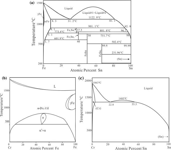
Experimental Investigation Of The Phase Relationship Of The Fe Cr Sn System Springerlink
2
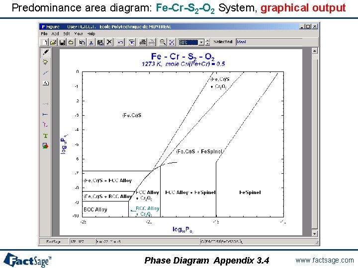
The Phase Diagram Module Use The Phase Diagram
Fe Cr Japan Atomic Energy Agency

Al Cr Fe Phase Diagram Isothermal Sections In The Region Above 50 At Al Sciencedirect

File Fe Cr Ni Solidus Phase Diagram Svg Wikimedia Commons

Review Precipitation In Austenitic Stainless Steels Precipitation Diagram Stainless Steel

Ni Laboratory
2
1 Fe Cr Phase Diagram A 18 Fe Cr 0 1c Phase Diagram B 19 Download Scientific Diagram
Analysis Of The Precipitation And Growth Processes Of The Intermetallic Phases In An Fe Ni Superalloy Intechopen
Collection Of Phase Diagrams
Figure 1 Overview Of Strategies For High Temperature Creep And Oxidation Resistance Of Alumina Forming Austenitic Stainless Steels Springerlink

Al Cr Fe Phase Diagram Isothermal Sections In The Region Above 50 At Al Sciencedirect
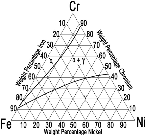
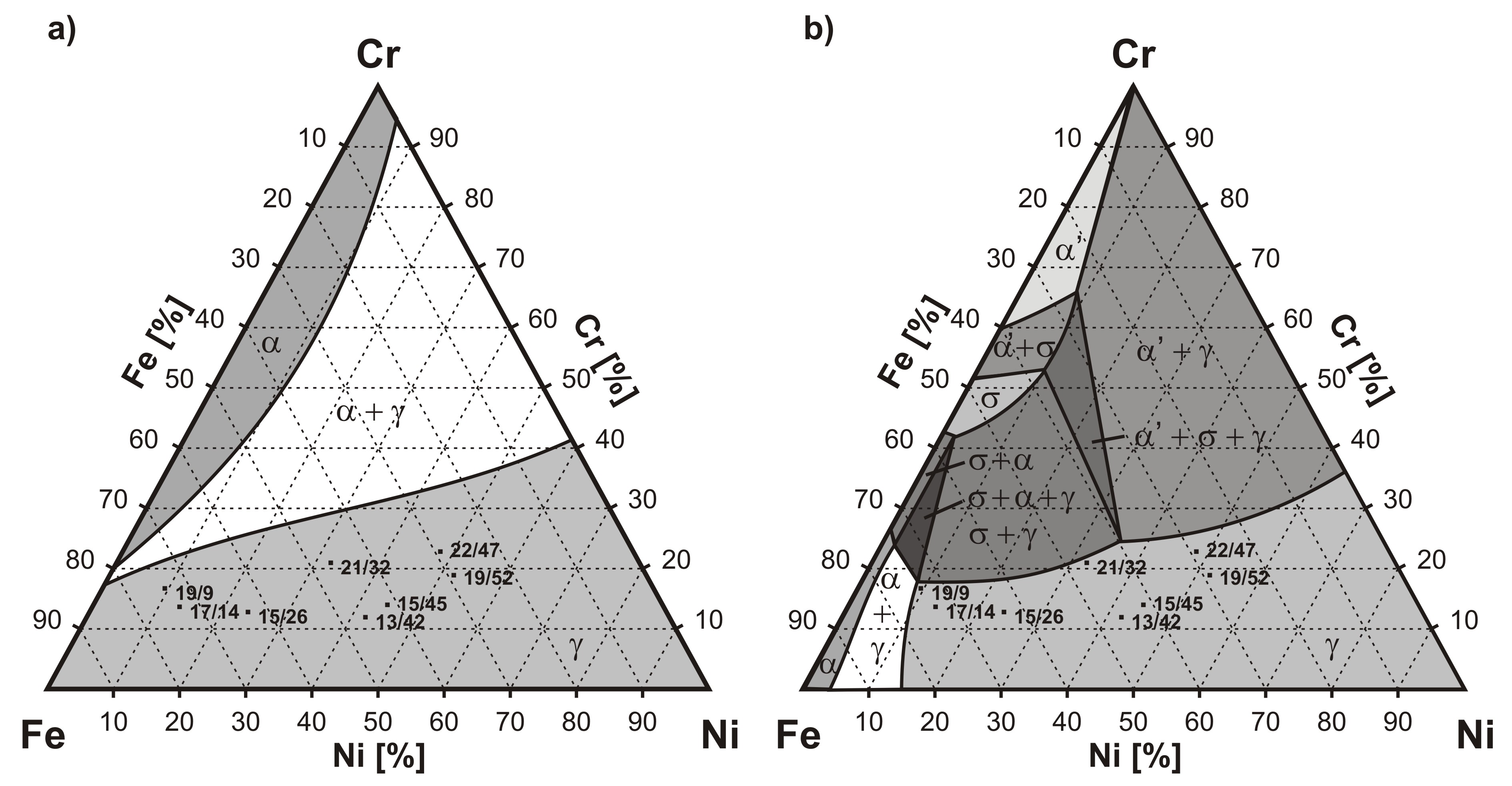
Ternary Diagram For Wrought Austenitic Stainless Steels
Short Term Mechanical Properties Of Fe Cr Al Si Alloys Kne Materials Science

Scielo Brasil Phase Transformations In An Aisi 410s Stainless Steel Observed In Directional And Laser Induced Cooling Regimes Phase Transformations In An Aisi 410s Stainless Steel Observed In Directional And Laser Induced
Fe Cr Binary Phase Diagram Adapted From Massalski See Ref 7 Download Scientific Diagram

File Phase Diagram Of Fe Cr 0 2 C Svg Wikimedia Commons
Fe Cr C

File Phase Diagram Of Fe Cr 0 2 C Svg Wikimedia Commons
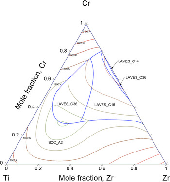
Thermodynamic Description Of Hydrogen Storage Materials Cr Ti Zr And Fe Ti Zr Journal Of Materials Research Cambridge Core

Determination Of The Fe Cr Ni And Fe Cr Mo Phase Diagramsat Intermediate Temperatures Using A Noveldual Anneal Diffusion Multiple Approach Semantic Scholar
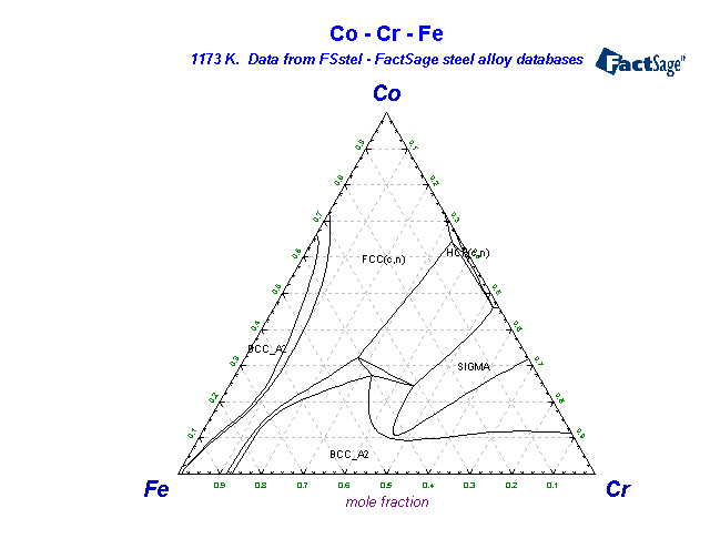
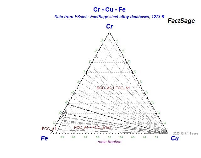
Fsstel Factsage Steel Alloy Phase Diagrams
2
Chromium In Steels Ispatguru

Example T 04 Ternary Phase Diagram Youtube

Revised Thermodynamic Description Of The Fe Cr System Based On An Improved Sublattice Model Of The S Phase Sciencedirect
Effect Of Heat Treatment Process Of Stainless Steel For Watch Manufacturing Application

Austenitic Steels Total Materia Article
Ppt General Phase Diagram Sections Powerpoint Presentation Free Download Id 431317

Fe Cr Binary Phase Diagram Adapted From Massalski See Ref 7 Download Scientific Diagram

A Thermodynamic Evaluation Of The Fe Cr C System Sciencedirect
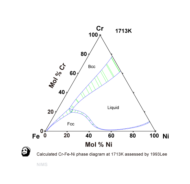
Cr Fe Ni Nims
0 Response to "39 fe cr phase diagram"
Post a Comment