41 how to draw bending moment diagram
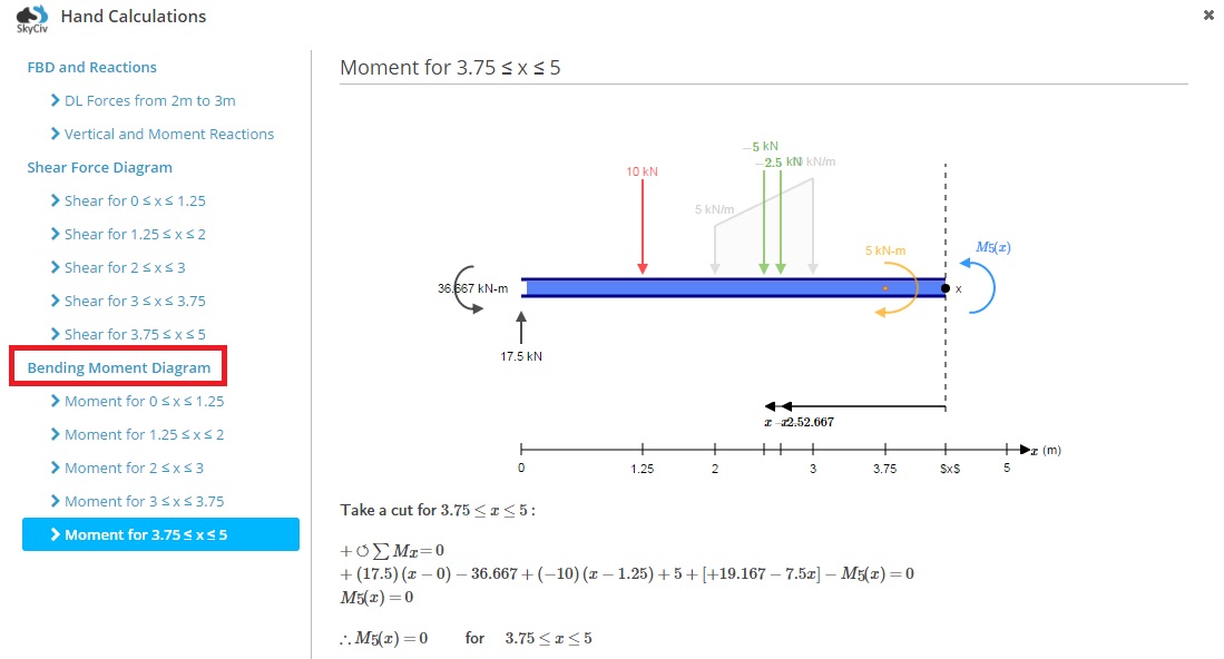
Shear and bending moment diagrams are analytical tools used in conjunction with structural analysis to help perform structural design by determining the value of shear force and bending moment at a given point of a structural element such as a beam. These diagrams can be used to easily determine the type, size, and material of a member in a ... 4.0 Building Shear and Moment Diagrams. In the last section we worked out how to evaluate the internal shear force and bending moment at a discrete location using imaginary cuts. But to draw a shear force and bending moment diagram, we need to know how these values change across the structure.
About the Beam Calculator. Welcome to our free online bending moment and shear force diagram calculator which can generate the Reactions, Shear Force Diagrams (SFD) and Bending Moment Diagrams (BMD) of a cantilever beam or simply supported beam. Use this beam span calculator to determine the reactions at the supports, draw the shear and moment ...
How to draw bending moment diagram
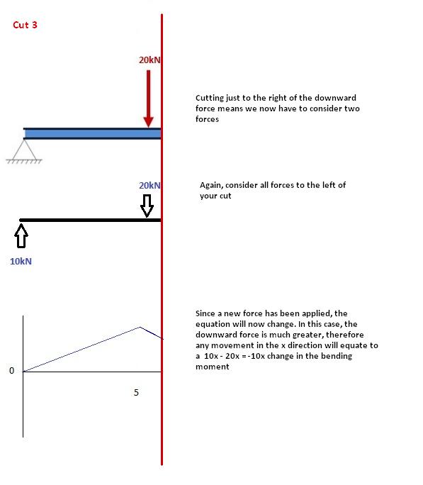
How to Draw Bending Moment Diagram. how to draw shear force and bending moment diagrams how do i draw shear force and bending moment diagrams strength of materials how to draw bending moment diagrams finally calculating the moments can be done in the following steps 2 from left to right make "cuts" before and after each reaction load to calculate the bending moment of a beam we must work in ... Shear Force and Bending Moment Diagram for simply supported beam version 1.0.0.0 (3.44 KB) by Sajeer Modavan This Matlab code can be used for finding Support reaction, Maximum Bending Moment, SFD and BMD Level 1: Single Point Load. This is example shows how to use the steps outlined in the "Steps" tab to draw shear force and bending moment diagrams. Level 2: Distributed Force. This example deals with a constant distributed force (shear is a linear function of x). Level 3: Point Moment.
How to draw bending moment diagram. This video explains how to draw shear force diagram and bending moment diagram with easy steps for a simply supported beam loaded with a concentrated load. S... Once you have the reactions, draw your Free Body Diagram and Shear Force Diagram underneath the beam. Finally calculating the moments can be done in the following steps: 2. From left to right, make "cuts" before and after each reaction/load. To calculate the bending moment of a beam, we must work in the same way we did for the Shear Force ... Bending Moment (M) equal in magnitude but opposite in direction to the algebraic sum of the moments about (the centroid of the cross section of the beam) the section of all external loads and support reactions acting on either side of the section being considered. What are the benefits of drawing shear force and bending moment diagram? Answer (1 of 2): Frame is the combination of beams (horizontal/vertical/inclined). There are various method for finding the final action coorosponding to the applied ...
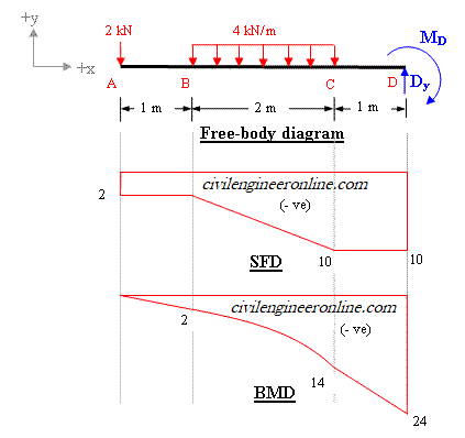
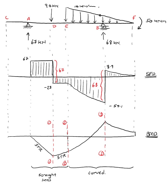
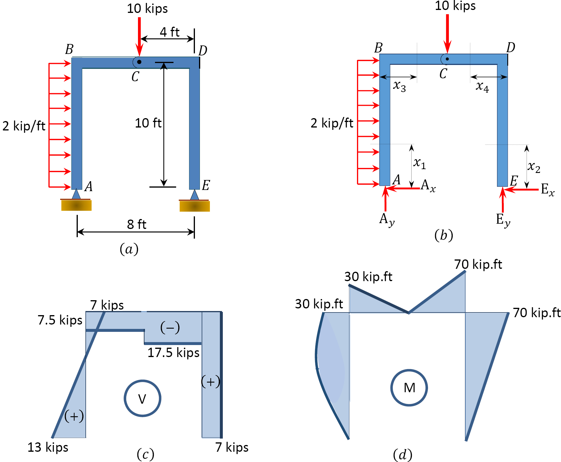
Step-4: Plot the Bending Moments: Just now you have calculated the BM values at different points of the beam, now plot the values and you will get the bending moment diagram like below: BMD of the problem. In the above BMD you might have observed for the point load bending moment diagram is a straight line and for UDL bending moment is a curve. Being able to draw shear force diagrams (SFD) and bending moment diagrams (BMD) is a critical skill for any student studying statics, mechanics of materials, or structural engineering. There is a long way and a quick way to do them. Shear and bending moment diagrams depict the variation of these quantities along the length of the member. Proceeding from one end of the member to the other, sections are passed. After each successive change in loading along the length of the member, a FBD (Free Body Diagram) is drawn to determine the equations express-ing the shear and ... The following is a procedure for constructing the shear and moment diagrams for a frame. Determine the support reactions for the frame, if possible. Determine the support reactions A, V, and M at the end of each member using the method of sections. Construct both shear and moment diagrams just as before.
Answer (1 of 6): Consider a simply supported beam of length 6 m. The beam is subjected to a udl ( uniformly distributed load of 10 kn/m) follow the following steps 1. Determine the reactions at the left and right end ( supports ). Let the reaction at the left end be Ay and That of the left end... The code, given below, is created using Python and using Numpy and Matplotlib libraries. It can draw the bending moment diagram(BMD) and Shear Force Diagram(SFD) for a Simply Supported Beam (SSB) with a point load at any location on that beam. The solution code when run will ask for the following inputs: Figure 4 Mouse Over for Bending Moment Diagram Method 2 Six Rules After students have practiced deriving V & M equations and drawing diagrams by the free body diagram method, the relationships between extern al distributed load, internal shear force, and internal bending moment are derived in the c ourse lecture. This video explains how to draw shear force & bending moment diagram in case of overhanging beam. It also explains how to locate the point of zero shear & po...
Bending moment at point B = M(B) = R1 x Distance of R1 from point B. Bending moment at point B = M (B) = 1000 x 2 = 2000 kg.m. Bending Moment Diagram Simply Support Beam with UDL & Point Load Example. Draw shear force and bending moment diagram of simply supported beam carrying uniform distributed load and point loads. As shown in figure. Solution
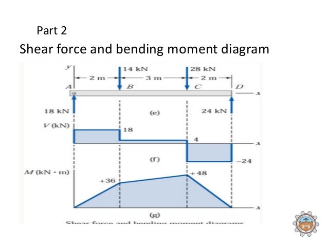
Steps to draw Shear force and Bending moment diagrams. In SFD and BMD diagrams Shear force or Bending moment represents the ordinates, and the Length of the beam represents the abscissa. Consider the left or the right portion of the section. Add the forces (including reactions) normal to the beam on the one of the portion.

Draw The Shear Force And Bending Moment Diagrams For The Loaded Beam And Determine The Maximum Moment M And Its Location X From The Left End Holooly Com
The ability to draw shear force and bending moment diagrams on beam-like components is an important skill for mechanical engineering students. We found that some students had difficulty to draw effectively the shear force and bending moment diagrams during the course and even in their senior year.
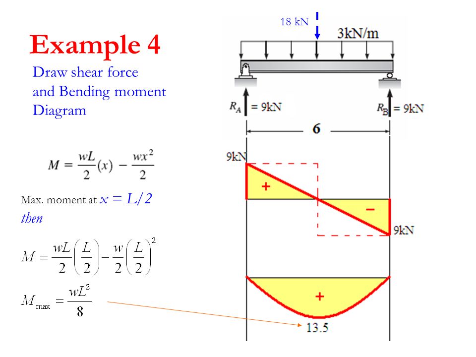
Structure Analysis I Lecture 8 Internal Loading Developed In Structural Members Shear Moment Diagram Ch 4 In Text Book Ppt Download
Drawing bending moment diagrams for different beam sections is also a very important part of the strength of material problems. Here, we explain how to draw bending moment diagrams effectively for all problems. Bending diagrams are represented with a straight horizontal line right below the beam. This line represents zero.
a) Calculate the shear force and bending moment for the beam subjected to a concentrated load as shown in the figure. Then, draw the shear force diagram (SFD) and bending moment diagram (BMD). b) If P = 20 kN and L = 6 m, draw the SFD and BMD for the beam. P kN L/2 L/2 A B EXAMPLE 4
The ending point on the moment diagram for this section will be . Put a dot at the end point ( 8.35 lbft) and draw a straight line to it ( this shear segment is also constant). The area for region 3 is 8.35 lb*ft and the shear is constant resulting in a linear moment. The moment at the end of this segment is 16.35 ft*lb.
2. Draw a FBD and apply Equilibrium (Sum Of Force and Moments) to solve for the Reactions 3. Draw the Shear, Normal, and Bending Moment Diagrams 4. Identify the critial locations, x along the structure where Vmax, Nmax, and Mmax exist. 5. Identify which stresses exist Normal Stress pure Shear Stress Transverse Shear Stress Normal Bending Stress
Jiro's pick this week is Shear Force Bending Moment by Lateef Adewale Kareem.. As an ex-mechanical engineer, I remember my statics course where I learned how to do shear force bending moment diagram.I remember really enjoying that topic, since the steps to drawing the diagram is very systematic.
This program calculates the shear force and bending moment profiles, draw. the free body, shear force and bending moment diagrams of the problem. Under the free body diagram, the equations of each section is clearly. written with Latex. To use this program, you call the function placing the arguments in cells.
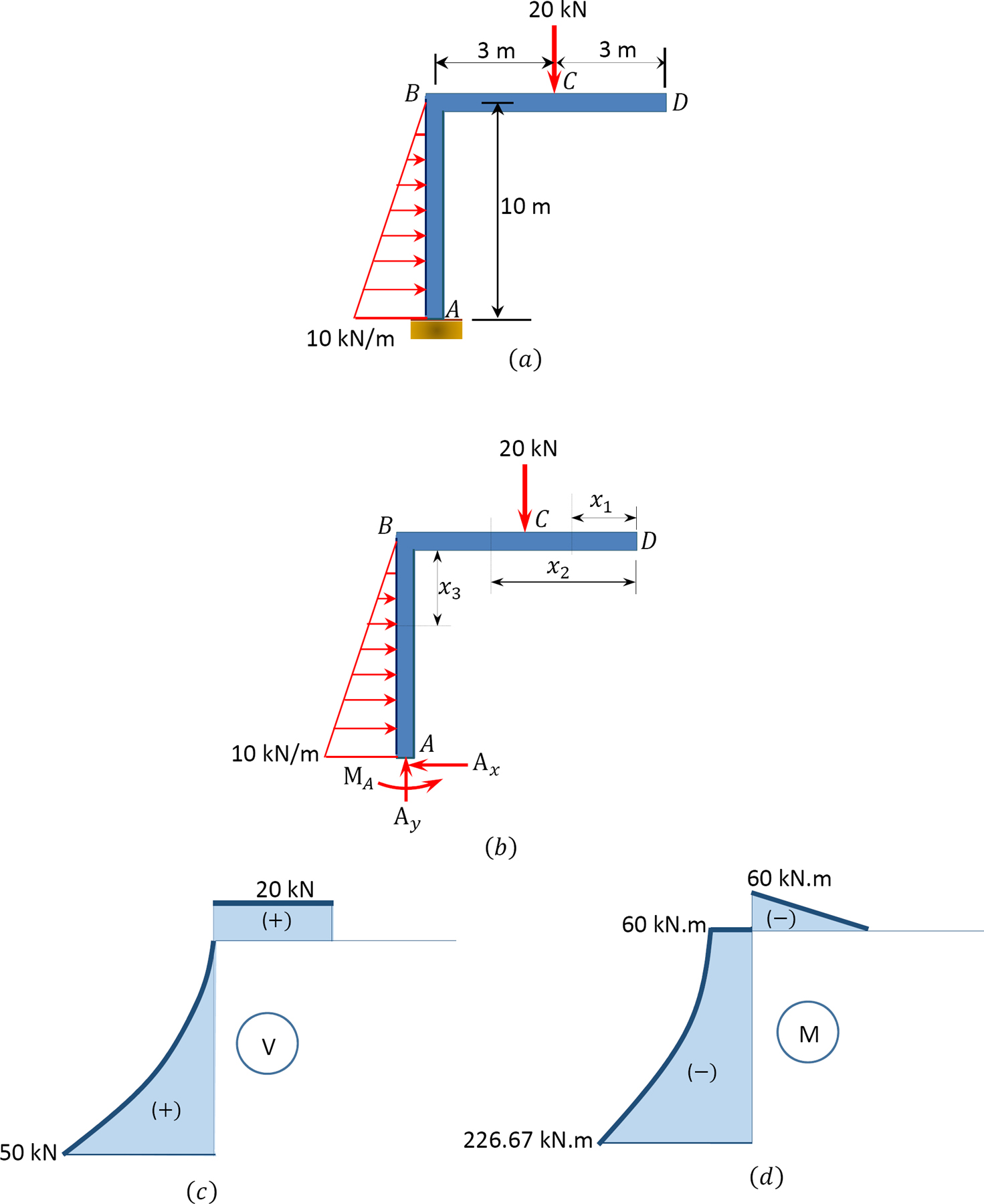
Shear and Moment Diagrams for Frames Next, solve the equations of equilibrium for member CD. M C 0 Fy 0 11.84k Cy C y= 11.84 k MC= 0 Fx 0Cx Cx= 0 11.84 k 16 ft. Cy Cx MC MC Shear and Moment Diagrams for Frames Now, let's draw the shear and moment diagram (remember to draw the diagram on the compression side of the member).
These instructions will help you to calculate and draw shear and bending moment diagram, as well as draw the resulting deflection. Knowing how to calculate and draw these diagrams are important for any engineer that deals with any type of structure because it is critical to know where large amounts of loads and bending are taking place on a beam so that you can make sure your structure can ...
Level 1: Single Point Load. This is example shows how to use the steps outlined in the "Steps" tab to draw shear force and bending moment diagrams. Level 2: Distributed Force. This example deals with a constant distributed force (shear is a linear function of x). Level 3: Point Moment.
Shear Force and Bending Moment Diagram for simply supported beam version 1.0.0.0 (3.44 KB) by Sajeer Modavan This Matlab code can be used for finding Support reaction, Maximum Bending Moment, SFD and BMD
How To Draw Shear Force Bending Moment Of Cantilever With Udl Point Loads Examples Engineering Intro
How to Draw Bending Moment Diagram. how to draw shear force and bending moment diagrams how do i draw shear force and bending moment diagrams strength of materials how to draw bending moment diagrams finally calculating the moments can be done in the following steps 2 from left to right make "cuts" before and after each reaction load to calculate the bending moment of a beam we must work in ...

Cantilever Beam Shear Force And Bending Moment Diagram In 2021 Bending Moment Shear Force In This Moment


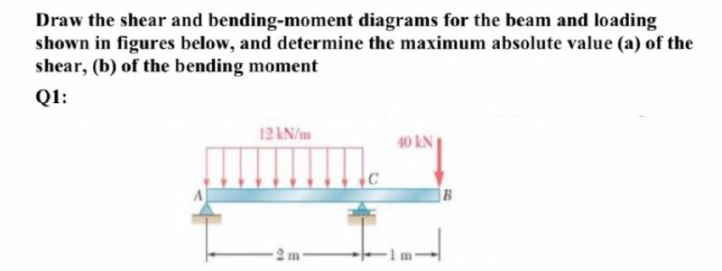







0 Response to "41 how to draw bending moment diagram"
Post a Comment