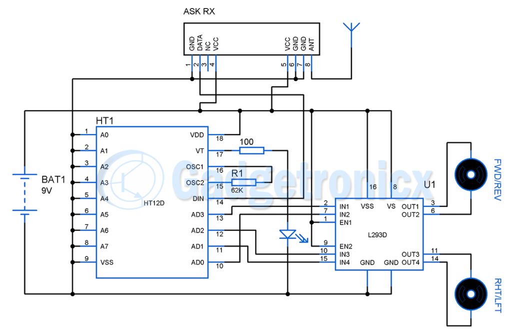
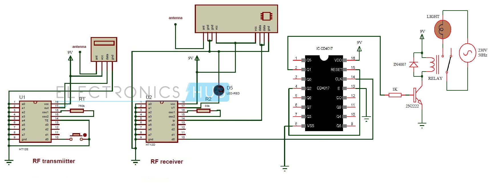
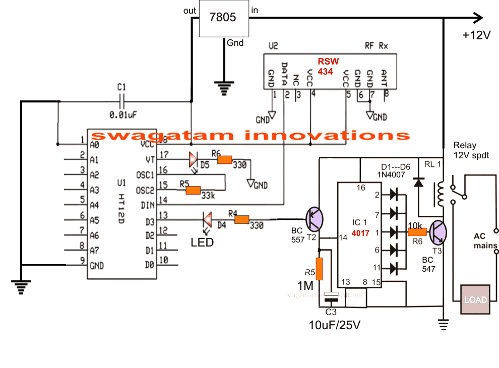
42 4 channel remote control circuit diagram
Respected sir We have one battery charger circuit with current control,voltage control circuit using LM324 ,555,tip127 components.In this all com pain circuit of saw tooth, triangulate,pulse generation circuit. We are drawn the avail circuit but we can’t identified the particular type of outputs. Hence kindly support us how can i sent to you the copy of drawing and i need the explanation of ... Electronic Component: Circuit Symbol: Description: Resistor: Resistor Circuit Symbol: A resistor is used to restrict the amount of current flow through a device. Abbreviated as ‘R’. Rheostat: Rheostat Circuit Symbol: A rheostat is used to control the current flow with two contacts. Applicable in controlling lamp brightness, capacitor charge rate, etc.
In electrical signalling an analog current loop is used where a device must be monitored or controlled remotely over a pair of conductors. Only one current level can be present at any time. A major application of current loops is the industry de facto standard 4–20 mA current loop for process control applications, where they are extensively used to carry signals from process instrumentation ...

4 channel remote control circuit diagram
May 06, 2021 · Snap a picture of the button configuration before opening the remote. It’s best to do this before opening the remote. Some of the buttons may come flying out when you open it. Use your phone or draw a diagram if you don’t have a user manual with one in it. Also, note and document the position of any screws on the remote. Apr 20, 2015 · Sequential Device Control using TV Remote Control This circuit lets you switch on and switch off up to nine devices sequentially from your TV remote control [33]. Aug 25, 2017 · Bluetooth Controlled Electronic Home Appliances Circuit Principle. In this project, a Bluetooth module is interfaced to 8051 Microcontroller.This Bluetooth Module receives the commands from the Android application that is installed on the Android device, using wireless communication (Bluetooth Technology).
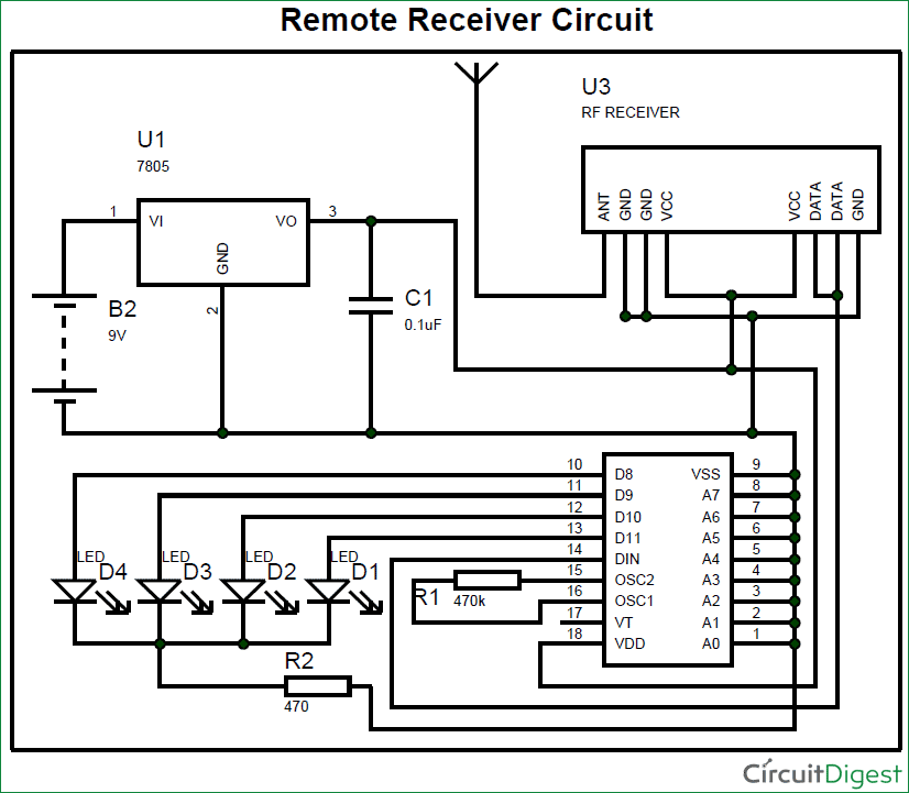
4 channel remote control circuit diagram. Bluetooth Circuits A Bluetooth circuit is the central part of a Bluetooth and contains components such as the integrated circuit, capacitors, and power source. The course supports wired-in audio, wireless stereo, Bluetooth module, and many more. We have professional standard reviewers that ensure strict quality control measures in every production process. We leverage advanced testing […] Aug 24, 2017 · Circuit Design. The above circuit of the Wireless Electronic Notice Board using GSM consists of 8051 Microcontroller, GSM Module (Modem) and 16 x 2 LCD.Here, the 16 x 2 LCD is used to display message and is used in 8 – bit mode. After pasting all the cardboard pieces, our remote control car is now ready. Connect a 5v mobile charger to completely charge the battery for the remote control car. Take the transmission remote and get ready to have fun with this amazing remote control F1 Car. Aug 25, 2017 · As said they have 4-data bit and 8-addresss bit, these 8 address bits has to be set same on both the encoder and decoder to make them work as a pair. Circuit Diagram of RF Transmitter and Receiver: The complete circuit Diagram including the Transmitter and Receiver part for this project is shown in the images below.
Aug 25, 2017 · Bluetooth Controlled Electronic Home Appliances Circuit Principle. In this project, a Bluetooth module is interfaced to 8051 Microcontroller.This Bluetooth Module receives the commands from the Android application that is installed on the Android device, using wireless communication (Bluetooth Technology). Apr 20, 2015 · Sequential Device Control using TV Remote Control This circuit lets you switch on and switch off up to nine devices sequentially from your TV remote control [33]. May 06, 2021 · Snap a picture of the button configuration before opening the remote. It’s best to do this before opening the remote. Some of the buttons may come flying out when you open it. Use your phone or draw a diagram if you don’t have a user manual with one in it. Also, note and document the position of any screws on the remote.

4 Channel Infra Remote Controller Using 4 Relay Ht12a Ht12d Circuit Ideas I Electronic Diy Projects I Robotics

Arduino 4 Channel Infra Red Remote Controlled On Off Switch Circuit Ideas I Electronic Diy Projects I Robotics

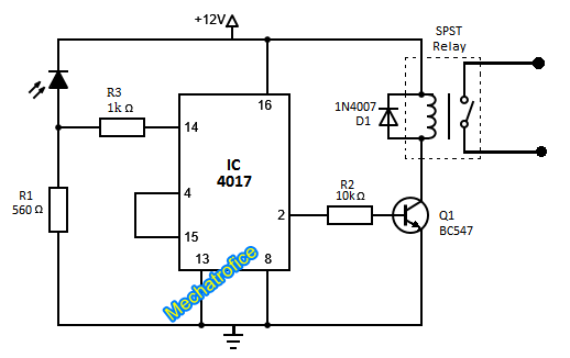
How To Make Wireless Ir Remote Control On Off Switch Using 4017 Ic Relay 4017 Circuits Projects Youtube

Jual Esp8266 Esp01 Relay 12v 4ch 4 Channel Wifi Remote Control Switch Modul Kota Medan Led House Tokopedia
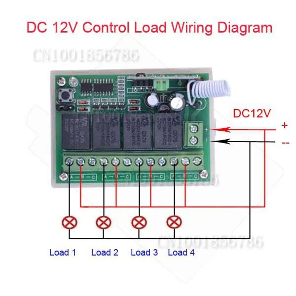
4 Channel Dc 12 V 4ch Rf Wireless Remote Control Beralih Sistem 315 Mhz 433 Mhz Transmitter Dan Receiver Controle 315 433 4chtransmitter Switch Aliexpress

4 Channel Infra Remote Controller Using 4 Relay Ht12a Ht12d Circuit Ideas I Electronic Diy Projects I Robotics

2 4ghz 4 Channel Wireless Transmitter Receiver Board Module For Diy Remote Control Cars Integrated Circuits Aliexpress

Ir Remote Control On Off Switch Circuit Envirementalb Com Remote Control Light Remote Control Circuit Diagram

Buy Dc 12v 4 Channel Relay 10a Rf Wireless Remote Control Switch System Receiver Transmitter Wireless Light Switch For Smart Home Relay Output No Com Nc Normally Open Normally Closed Common Terminal Online In

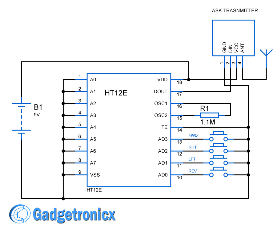


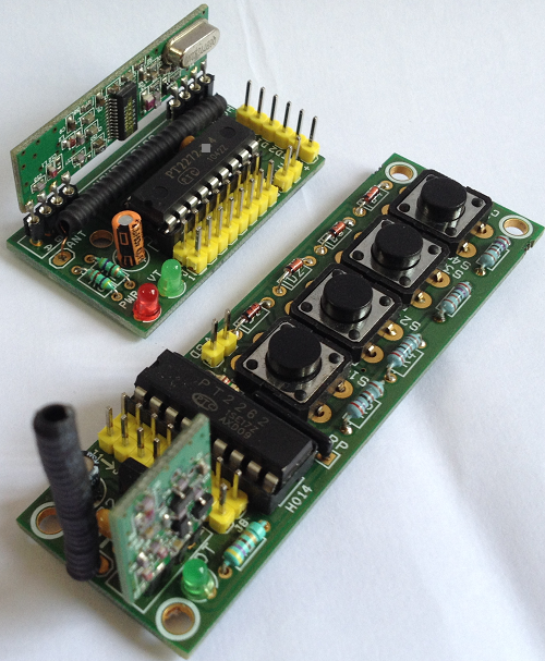


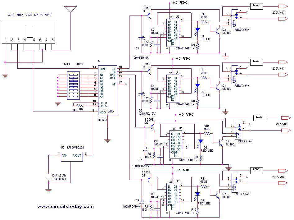




0 Response to "42 4 channel remote control circuit diagram"
Post a Comment