38 free body diagram statics
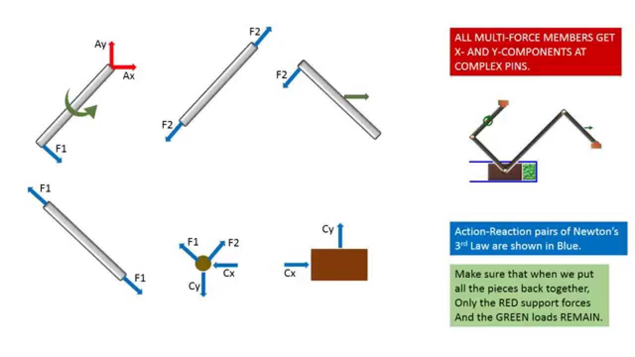
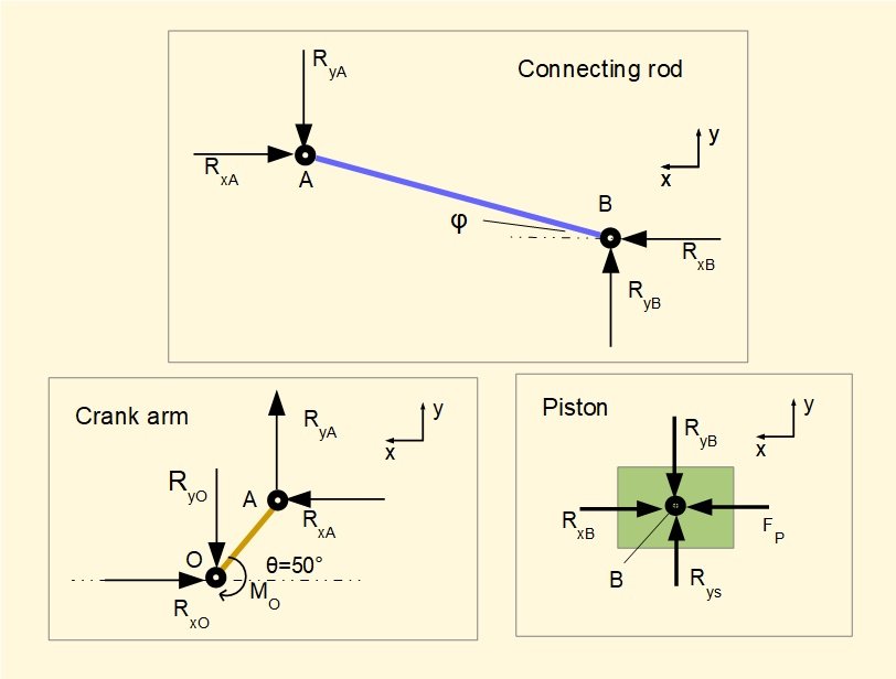
Force due to static friction is coefficient of friction * Normal reaction. As the body is resting on an inclined plane, the normal reaction is not equivalent to weight, but the component of it perpendicular to the plane on which the body rests. You need to resolve all the forces in your diagram, to arrive on your answer. 6.1 Free Body Diagram We begin by considering the free body diagram of an individual link involved in an open kinematic chain. Figure 6.1.1 shows the forces and moments acting on link i, which is connected to link i-1 and link i+1 by joints i and i+1, respectively. Let Oi be a point fixed to link i located
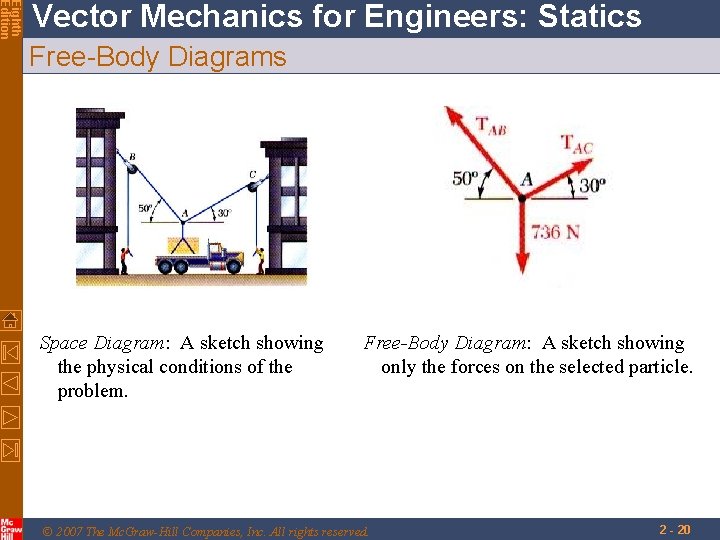
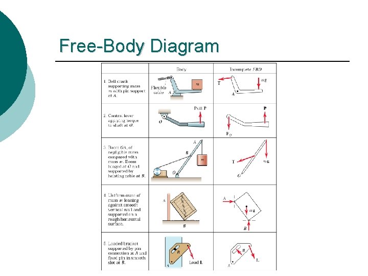
Edition Eighth Vector Mechanics for Engineers: Statics Contents Introduction Equilibrium of a Rigid Body in Three Free-Body Diagram Dimensions Reactions at Supports and Connections Reactions at Supports and Connections for a for a Two-Dimensional Structure Three-Dimensional Structure Equilibrium of a Rigid Body in Two Sample Problem 4.8 ...
Free body diagram statics
FREE-BODY DIAGRAMS (Section 5.2) 1. Draw an outlined shape. Imagine the body to be isolated or cut "free" from its constraints and draw its outlined shape. 2. Show all the external forces and couple moments. These typically include: a) applied loads, b) the weight of the body, and c) support reactions (can be difficult). Free Body Diagram Example : A Free-body diagram (FBD) is an essential tool when the forces on an object need to be determined using equilibrium equations. They help focus attention on the object of interest in order to determine the forces acting on it. Creating FBD's is a straightforward process: Identify the object that will be isolated. In physics and engineering, a free body diagram (force diagram, or FBD) is a graphical illustration used to visualize the applied forces, moments, and resulting reactions on a body in a given condition. They depict a body or connected bodies with all the applied forces and moments, and reactions, which act on the body (ies).
Free body diagram statics. Draw free body diagram for both boxes. N 2mg mg T T 2. Select axes x y x 3. Write Newton's 2nd law T mg ma ... The free body diagram is one of the most important ideas in statics. Here's a description along with an easy example. 1.-. With a thick black line I draw the free body diagram FBD which isolates the body from the exterior world. In this case the body is the rectangular blue bar, and the forces acting on it are weight W acting at the center of the body, normal N and friction F forces at B, and the vertical Fa force at A. 2.-. Free-body diagram (FBD) 1. Draw an outlined shape. Imagine the body to be isolated or cut "free" from its constraints and draw its outlined shape. FREE-BODY DIAGRAMS (Section 5.2) Statics:The Next Generation (2nd Ed.) Mehta, Danielson, & Berg Lecture Notes for Sections 5.1,5.2 3.
Engineering Statics uses algebra and trigonometry and is suitable for use with either calculus- or non-calculus-based academic statics courses. Completion of a beginning physics course is helpful for success in statics, but not required as all the key concepts are included in this course. Topics Covered: Forces; Free Body Diagrams In solving problems in Mechanics, mainly in Statics, the important step is to draw the free body diagram FBD. The free body diagram is a material point or a particle that represents an object of interest to study. It is located in the origin of a coordinate system. It uses the particle model. 2. Drawing free-body diagram, the steps. Draw a picture of the situation, that is the motion diagram, Free body diagrams are the tool that engineers use to identify the forces and moments that influence an object. They will be used extensively in statics, and you will use them again in other engineering courses so your effort to master them now is worthwhile. Although the concept is simple, students often have great difficulty with them. 🔗. diagrams play a crucial role in the statics of rigid bodies. A free-body diagram is a road map that enables one to identify all the unknown loads (forces and moments) prior to the formulation and solution of equilibrium equations. In this section, we provide some hints to simplify this task, and will look at some examples of free-body diagrams.
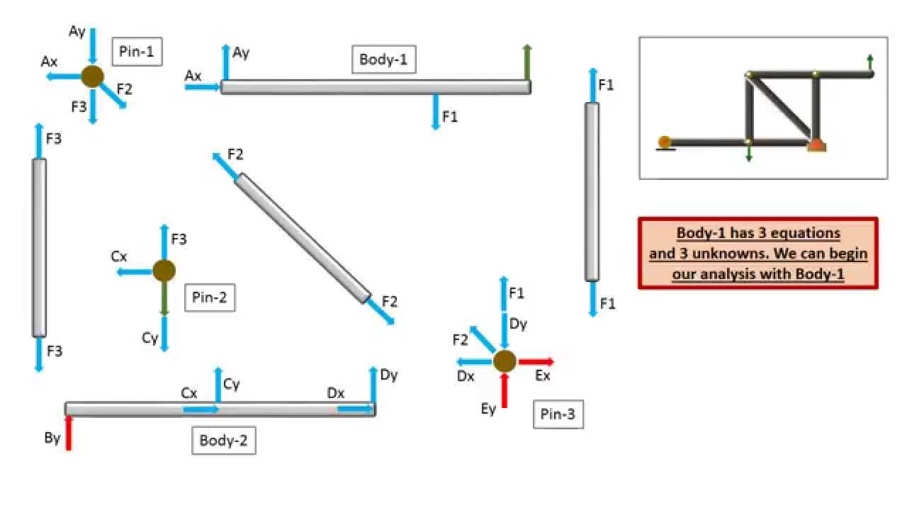
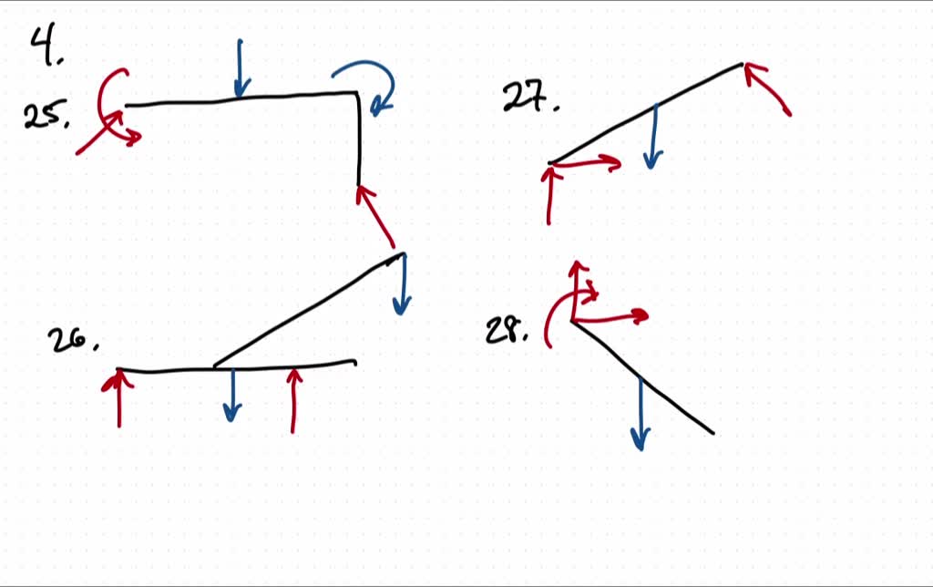
As with all statics problem, a free-body diagram will assist in solving the problem. In this example, all forces acting on the elevator cabin is first analyzed. The 5000 lb weight is divided evenly between the cables due to symmetry. Consequently the force of each cable will be. P = 5000 / 2 = 2,500 lb. directly on the diagram. Pertinent dimensions may also be represented for convenience. Note, however, that the free-body diagram serves the purpose of focusing accurate attention on the action of the external forces; therefore, the diagram should not be cluttered with excessive information. Force arrows Section 8.5 Section Cut Method. In this section we'll extend the method of Section 8.3 where we found internal loadings at a specific point to make shear and bending moment diagrams. The procedure is similar except that the cut is taken at a variable position designated by \(x\) instead of at a specified point. The analysis produces equations for shear and bending moments as functions of \(x ... So I've either made a mistake with my free body diagram or I'm doing something wrong with the second moment. Here are my equalibrium calculations: Body 1: Σ M A = C y ⋅ 2 a + G 2 2 = 0 Σ F x = A x − C x + G 2 2 = 0 Σ F y = A y + C y + G 2 2 = 0. Body 2: Σ M B = 3 a ⋅ C x = 0 Σ F x = C x + B x = 0 Σ F y = B y − C y = 0.
Figure2:Acantileveredbeam. Free-body diagrams Asasimplestartingexample,considerabeamclamped(\cantilevered")atoneendandsub-jectedtoaloadPatthefreeendasshowninFig.2 ...

The free-body diagram for a body is a useful tool that allows us to count correctly all contributions from all external forces and torques acting on the body. Free-body diagrams for the equilibrium of an extended rigid body must indicate a pivot point and lever arms of acting forces with respect to the pivot.
An educational video from Actus Potentia. Free Body Diagram, frames, internal forces, equilibrium equations, solution strategy, examples.

This is a statics and dynamics text for second or third year engineering students with an emphasis on vectors, free body diagrams, the basic momentum balance principles, and the utility of computation. Students often start a course like this thinking of mechanics reasoning as being vague and complicated. Our aim is to replace this
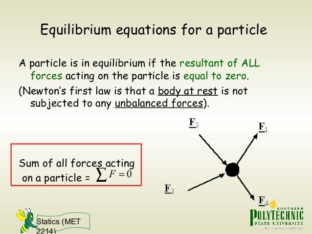
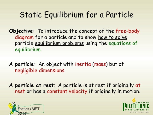
Statics (MET 2214) Free-Body Diagram (FBD): To apply equilibrium equations we must account for all known and unknown forces acting on the particle. The best way to do this is to draw a free-body diagram of the particle. FBD: A diagram showing the particle under consideration and all the forces and moments acting on this particle.
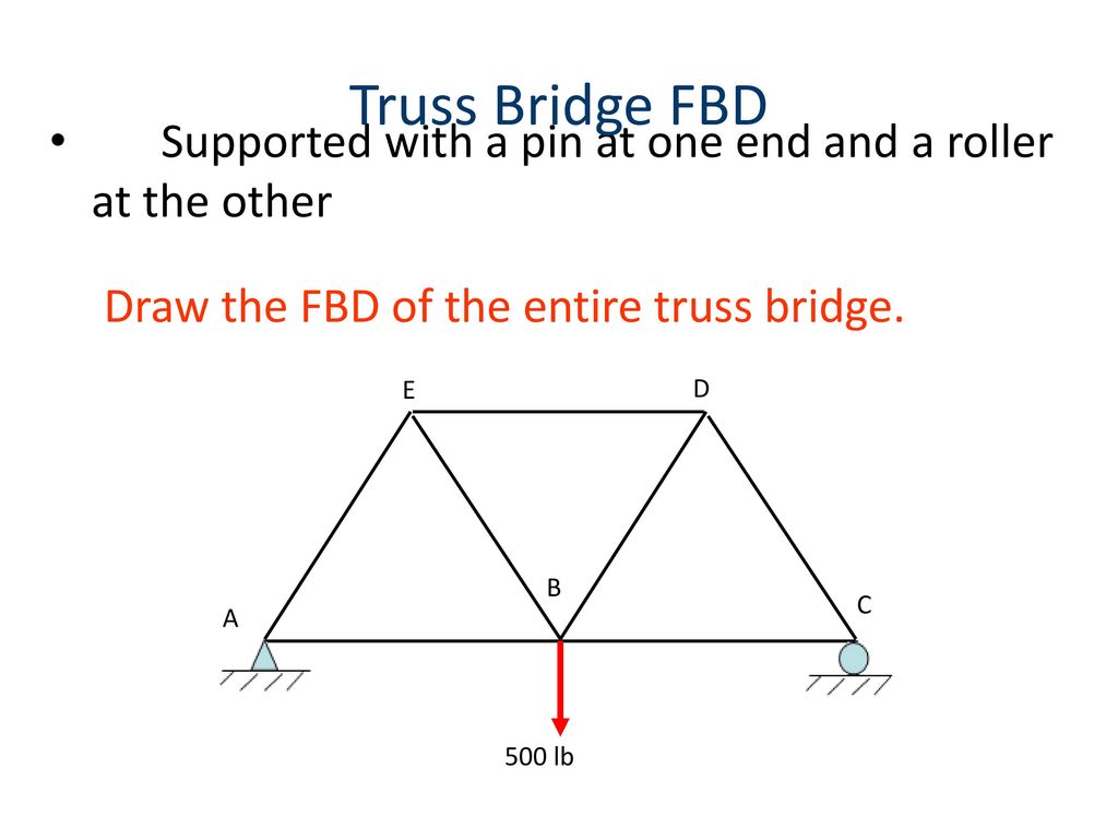
Figure M4.3-7 Geometry and free body diagram of indeterminate beam main beam house walls concrete wall concrete lally wall columns ~ ~ ~ ~ ~ ~ ~ F F ~ ~ ~ ~ ~ FREE BODY DIAGRAM:--> We will save looking at the statically indeterminate case for a later unit. Let's start off by considering….
https://goo.gl/ICIenR for more FREE video tutorials covering Engineering Mechanics (Statics & Dynamics)This video represents a comprehensive example of solvi...
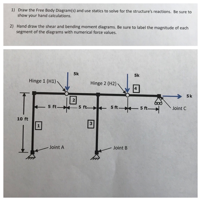
Constructing the Free Body Diagram. The first step in solving most mechanics problems will be to construct a free body diagram. This simplified diagram will allow us to more easily write out the equilibrium equations for statics or strengths of materials problems, or the equations of motion for dynamics problems.
Forces Statics and FBD's Intro 6th.notebook 2 November 08, 2016 Objectives: •Students will understand what a force is and what forces can do •Students will understand what is meant by static equilibrium •Students will be able to correctly draw Free Body Diagrams
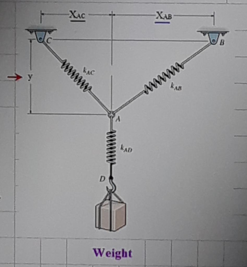
15. How to draw good free-body diagrams (FBDs) 16. Why is the tension the same everywhere in a rope 17. How to calculate forces of three ropes pulling in different directions 18. Using symmetry in statics problems 19. How to find the mass pulling on a spring when given the deflection 20. How to find the force exerted by a spring 21.

This is where the free-body diagram (FBD) comes in. FBD is the most important step in any mechanics problem and is often overlooked by students. The principle is to isolate the object of interest, replacing all actions/supports into its equivalent forces acting on the body. We do this because we must identify all forces acting on a body before proper mechanics analysis can be conducted.
Free-body diagrams are diagrams used to show the relative magnitude and direction of all forces acting upon an object in a given situation. A free-body diagram is a special example of the vector diagrams that were discussed in an earlier unit. These diagrams will be used throughout our study of physics.
Set up a free-body diagram for the object. (a) Choose the xy-reference frame for the problem. Draw a free-body diagram for the object, including only the forces that act on it. When suitable, represent the forces in terms of their components in the chosen reference frame.

A free body diagram is a tool used to solve engineering mechanics problems. As the name suggests, the purpose of the diagram is to "free" the body from all other objects and surfaces around it so that it can be studied in isolation.

A free-body diagram is a representation of an object with all the forces that act on it. The external environment (other objects, the floor on which the object sits, etc.), as well as the forces that the object exerts on other objects, are omitted in a free-body diagram. Below you can see an example of a free-body diagram:

What are Free Body Diagrams? One of the most useful aids for solving a statics problem is the free body diagram (FBD). A free body diagram is a graphic, dematerialized, symbolic representation of the body (structure, element or segment of an element) in which all connecting "pieces" have been removed. A FBD is a
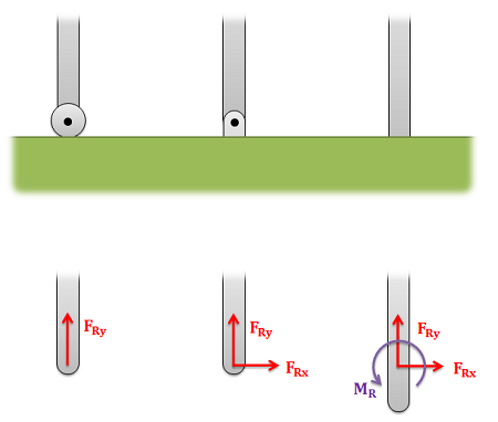
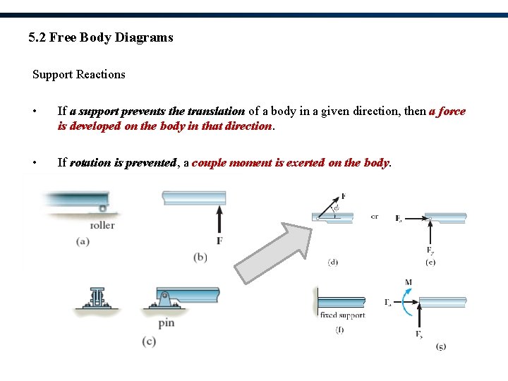
Statics: Lecture Notes for Sections 5.1,5.2 1 Chapter 5 EQUILIBRIUM OF A RIGID BODY EQUILIBRIUM OF A RIGID BODY & FREE-BODY DIAGRAMS Today's Objectives: Students will be able to: a) Identify support reactions, and, b) Draw a free-body diagram. READING QUIZ 1. If a support prevents translation of a body, then the support exerts a _____ on the ...
In physics and engineering, a free body diagram (force diagram, or FBD) is a graphical illustration used to visualize the applied forces, moments, and resulting reactions on a body in a given condition. They depict a body or connected bodies with all the applied forces and moments, and reactions, which act on the body (ies).
Free Body Diagram Example : A Free-body diagram (FBD) is an essential tool when the forces on an object need to be determined using equilibrium equations. They help focus attention on the object of interest in order to determine the forces acting on it. Creating FBD's is a straightforward process: Identify the object that will be isolated.

FREE-BODY DIAGRAMS (Section 5.2) 1. Draw an outlined shape. Imagine the body to be isolated or cut "free" from its constraints and draw its outlined shape. 2. Show all the external forces and couple moments. These typically include: a) applied loads, b) the weight of the body, and c) support reactions (can be difficult).


0 Response to "38 free body diagram statics"
Post a Comment