39 pv diagram problems and solutions
Engineering Thermodynamics: Chapter-10 Examples. A Carnot vapor refrigeration cycle is used to maintain a cold region at 0 o F where the ambient temperature is 75 o F. Refrigerant R-134a enters the condenser as saturated vapor at 100 lbf/in 2 and leaves as saturated liquid at the same pressure. The evaporator pressure is 20 lbf/in 2.The mass flow rate of refrigerant is 12 lbm/s. This physics video tutorial provides a basic introduction into PV diagrams. It explains how to calculate the work done by a gas for an isobaric process, iso...
Figure shows the P-V diagram of an ideal gas. ... Answer (Detailed Solution Below). Option 3 : 1.5PV ... More First Law of Thermodynamics Questions.1 answer · Top answer: "Concept: (W = mathop smallint limits_{{v_1}}^{{v_2}} pdV = Pleft( {{V_2} - {V_1}} right)) Work Done = Area under P – V diagram Calculation: Given: ...
Pv diagram problems and solutions
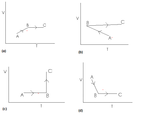
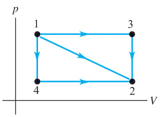
Practice Problems, Chapters 1 - 4 1. Use the P-V diagram below to answer the following questions 1a) The Net Work for the cyclic process is: a) Zero b) Positive c) Negative d) Cannot tell from the diagram 1b) The processes from states 1 to 2 and 3 to 4 are: a) Isothermal b) Isobaric c) Isochoric d) Isometric Solar system problems may have complex causes, but solving them is usually routine. It just takes experience to get started off on the right foot. Keeping track of your system's performance is an easy, effective troubleshooting solution. So is staying in touch with a specialist. 1. PV diagram below shows an ideal gas undergoes an isothermal process. Calculate the work is done by the gas in the process AB. Solution Work done by a gas is equal to the area under the PV curve AB = triangle area + rectangle area W = [½ (8 x 10⁵-4 x 10⁵) (3-1)] + [4 x 10⁵ (3-1)] W = [½ (4 x 10⁵) (2)] + [4 x 10⁵ (2)] W = [4 x 10⁵] + [8 x 10⁵]
Pv diagram problems and solutions. Examples and Problems. Reading: Elements Ch. 1-3 ... Ideal Gas p-V, p-T Diagrams ... Solution. 1) Consider the two paths, ia, and af connecting.29 pages EXAMPLE 8.15 (PV diagram) A gas expands from volume 1m3 to 2m3 at constant atmospheric pressure. (a) Calculate the work done by the gas. (b) Represent the work done in PV diagram. Solution (a) The pressure P = 1 atm = 101 kPa, V f =2 m 3 and V 1 = 1m 3. From equation (8.17) W = Since P is constant. It is taken out of the integral. - Something you see a lot when doing thermodynamics especially problems involving the first law are what are called PV Diagrams. Now, the P stands for Pressure and the V stands for Volume. And this gives you a diagram of what the pressure and volume are in any given instant. pV γ=constant =1 1 =constant pV γ pVγ 1 constant 2 2 1 1 1 = = T Vγ− T V γ− pV =nRT During an adiabatic expansion process, the reduction of the internal energy is used by the system to do work on the environment. During an adiabatic compression process, the environment does work on the system and increases the internal energy.
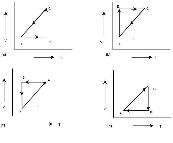
The PV diagrams for a thermodynamical system is given in the figure below. Calculate the total work done in each of the cyclic processes shown. Solution In the case (a) the closed curve is anticlockwise. So the net work done is negative, implying that the work done on the system is greater than the work done by the system. 1. PV diagram below shows an ideal gas undergoes an isobaric process. Calculate the work is done by the gas in the process AB. Known : Pressure (P) = 5 x 10⁵ N/m2 Initial volume (V1) = 2 m3 Final volume (V2) = 6 m3 Wanted : Work (W) Solution : W = P (V2 … Isobaric thermodynamics processes - problems and solutions Read More » P-V Diagrams. In science and engineering the use of diagrams to facilitate problem solving is a widespread practice. Thermodynamics is no exception. For example ...1 answer · Top answer: Here's the information that we need to use: • W is the work (negative if it enters the system) • Q is the heat flux (negative if it leaves the system) ... Problems practice. One mole of an ideal, monatomic gas runs through a four step cycle. All processes are either isobaric or isochoric. The pressure and volume of the gas at the extreme points in the cycle are given in the table below. Sketch the PV graph of this cycle. Determine the temperature at state A, B, C, and D.
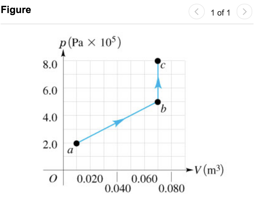
Below is a Pressure-Volume diagram. In "geek-speak" it is called a "PV diagram." Notice that is looks like a graph, but it's not. It's a diagram. This diagra... Sketch the cycle path on a PV Diagram b.) Calculate the net work done in kJ Data: T 1 = 145 o C, T 2 = 440 o C, P 1 = 150 kPa : Read : Work your way around the cycle, step by step. The work for the cycle is the sum of the work for each step. Assume the CO 2 behaves as an ideal gas throughout all three process steps. Physics questions and answers. Exercise 19.13 - Enhanced - with Solution The pV diagram in the figure (Figure 1) shows a process abc involving 0.540 mol of an ideal gas. You may want to review (Pages 623 - 628). For related problemsolving tips and strategies, you may want to view a Video Tutor Solution of A cyclic process. Example of Rankine Cycle - Problem with Solution. Let assume the Rankine cycle, which is the one of most common thermodynamic cycles in thermal power plants. In this case assume a simple cycle without reheat and without with condensing steam turbine running on saturated steam (dry steam). In this case the turbine operates at steady state with inlet conditions of 6 MPa, t = 275.6°C, x = 1 ...
On Cycle Pv Diagram Thermo - Wiring Diagram DB
look at PV diagrams. A PV diagram is a graph of Pressure as a function of Volume. There are four different situations that you can expect to see shown in PV diagrams: 1. Isobaric: the gas is held at a constant pressure 2. Isochoric: the gas is held at a constant volume 3. Isothermal: the gas is held at a constant temperature 4.
P-V Diagram Problems and Solutions
4 - The trapezoidal rule gives an acceptable estimate of the area under the process path in the PV Diagram. Equations / Data / Solve: Part a.) The area of each trapezoid under the process path in the PV Diagram is the product of the average pressure for that trapezoid and the change in volume across the trapezoid.

PhD Research Assistance
Problem: Solution: Reasoning: The process is isobaric. For an isobaric process W = P(V 2 - V 1). Details of the calculation: W = P(V 2 - V 1) = P(2V 1 - V 1) = PV 1 = 151500 Pa*4 m 3 = 606000 J. (The work is the area under curve in the PV diagram. ΔV is positive because the gas expands, and therefore the work W done by the gas is positive ...

Ch8, Lesson C, Page 14 - 3-Stage Compression With Intercooling
Rankine Cycle Equations or Formula. The general efficiency equation of the simple Rankine cycle, Thermal efficiency = W Turbine - W Pump / Q Boiler. Where, W Turbine is the work output. W Pump is work input. Q Boiler is the heat supplied. Let's consider the followings, h 1: Enthalpy at point 1.
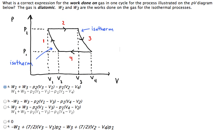
Solved: What Is A Correct Expression For The Work Done On ...
the power flow problem results in algebraic nonlinear equations ... Instructions for PV bus solution ... For the one-line diagram shown below, using the G-S method to determine all bus voltages (magnitude and phase) and

Schematic Diagram of PV powered Sailing Boat | Download ...
First law of thermodynamics problem solving. PV diagrams - part 1: Work and isobaric processes. PV diagrams - part 2: Isothermal, isometric, adiabatic processes. Second law of thermodynamics. Next lesson. Thermochemistry.
P-V Diagram Problems and Solutions
PV of a deferred annuity = $5,550.18 / 1.04 = $5,336.71 d) three years from today. PV of a deferred annuity = $5,550.18 / 1.042 = $5,131.45 e) four years from today. PV of a deferred annuity = $5,550.18 / 1.043 = $4,934.09 Solutions to Time Value of Money Practice Problems 4

Image from page 141 of "Armour engineer" (1910)
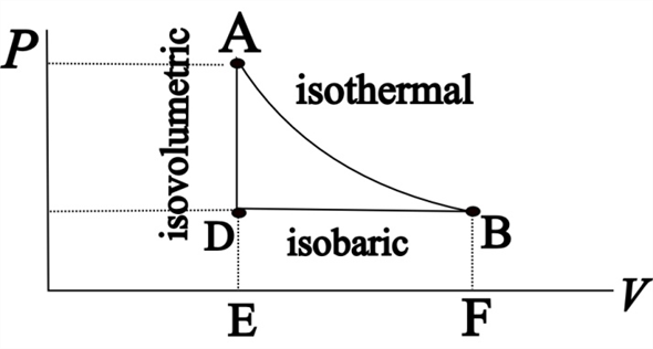
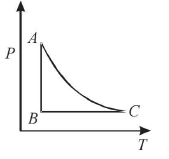
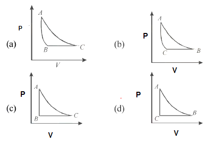
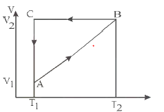
A cyclic Process is shown in the given below p-T digram. Which of the following curves shows the same process in p-V diagram Solution (a) This can be easily solved with ideal Gas equation P V =nRT P V = n R T At constant T, P is inversely proportional to V .An isotherm Curve At constant Pressure, Volume is directly proportional to T.

Ch8, Lesson B, Page 11 - Ws, Polytropic Processes, Open ...
Problem: Isobaric, Isochoric, Isothermal, and Adiabatic Processes Learning Goal: To recognize various types of processes on pV diagrams and to understand the relationship between pV-diagram geometry and the quantities Q, W, and ΔU. The first law of thermodynamics is an expression of conservation of energy. This law states that changes in the internal energy of a system Δ U can be explained ...
Solved: Is the work done by the gas in process ADB of Fig ...
Force of gravity and gravitational field - problems and solutions. In the pV diagram it is represented by a horizontal line. All material given in this website is a property of Isothermal thermodynamic processes - problems and solutions. look at PV diagrams. In a cyclic Process,heat is absorbed by a gas when the work done by it is positive.
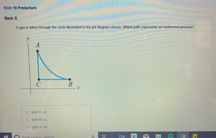
Solved: Ch 19 Prelecture Item 5 A Gas Is Taken Through The ...
1. Chapter 9 Capital Budgeting Techniques Solutions to Problems Note to instructor: In most problems involving the internal rate of return calculation, a financial calculator has been used. P9-1. LG 2: Payback Period Basic (a) $42,000 ÷ $7,000 = 6 years (b) The company should accept the project, since 6 < 8. P9-2.
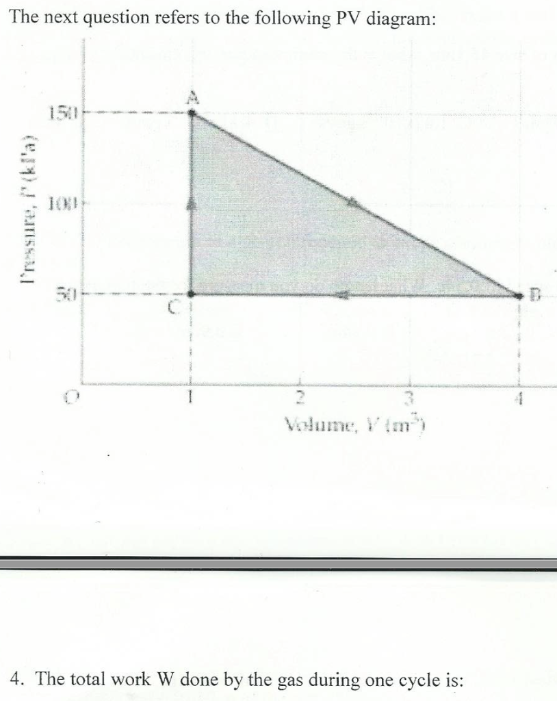
Solved: The Next Question Refers To The Following PV Diagr ...
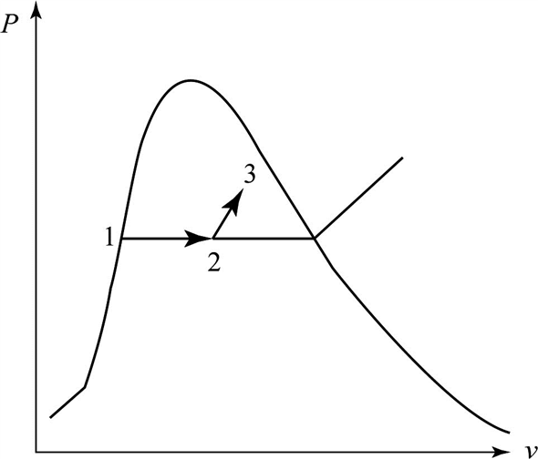
Problems and solutions statistical physics 1 1. ... Problem 4: Sargent Cycle C The diagram above is an approximation to a Sargent cycle run on an ideal gas. A constant pressure path and a constant volume path are connected by two adiabatic paths. Assume all processes are quasi-static and that the heat capacities, CP and V , are constant.

Closeup of skeleton foot model
pV diagram of Otto Cycle. The area bounded by the complete cycle path represents the total work that can be done during one cycle. In this example let assume an Otto cycle with compression ratio of CR = 9 : 1. The intake air is at 100 kPa = 1 bar, 20 °C, and the volume of the chamber is 500 cm³ prior to the compression stroke.
Solved: A piston-cylinder device contains 50 kg of water ...
Work & PV Diagrams. Q. Work Done by the Lungs. The graph (Figure 1) shows a pV-diagram of the air in a human lung when a person is inhaling and then exhaling a deep breat... Solved • Jul 14, 2020. Work & PV Diagrams. Q. A) Find w12, the work done on the gas as it expands from state 1 to state 2.Express the work done in terms of Po and VoB ...
P-V Diagram Problems and Solutions
1. PV diagram below shows an ideal gas undergoes an isothermal process. Calculate the work is done by the gas in the process AB. Solution Work done by a gas is equal to the area under the PV curve AB = triangle area + rectangle area W = [½ (8 x 10⁵-4 x 10⁵) (3-1)] + [4 x 10⁵ (3-1)] W = [½ (4 x 10⁵) (2)] + [4 x 10⁵ (2)] W = [4 x 10⁵] + [8 x 10⁵]
P-V Diagram Problems and Solutions
Solar system problems may have complex causes, but solving them is usually routine. It just takes experience to get started off on the right foot. Keeping track of your system's performance is an easy, effective troubleshooting solution. So is staying in touch with a specialist.

The pV diagram shown is for 7.50 moles of an ideal ...
Practice Problems, Chapters 1 - 4 1. Use the P-V diagram below to answer the following questions 1a) The Net Work for the cyclic process is: a) Zero b) Positive c) Negative d) Cannot tell from the diagram 1b) The processes from states 1 to 2 and 3 to 4 are: a) Isothermal b) Isobaric c) Isochoric d) Isometric

(PDF) THERMODYNAMICS

Physics Problems & Solutions: Thermal Physics - Ideal Gas
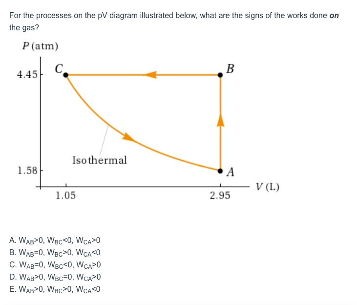
Solved: For The Processes On The PV Diagram Illustrated Be ...

Schematic Diagram of the problem | Download Scientific Diagram

CBSE Class 11 Physics: Thermodynamics Problem's: Questions ...

Ch9, Lesson F, Page 1 - Techniques for Improving Brayton ...

Ch9, Lesson E, Page 1 - Introduction to Gas Power Cycles

Solved: Calculate The Work W Done By The Gas During Proces ...
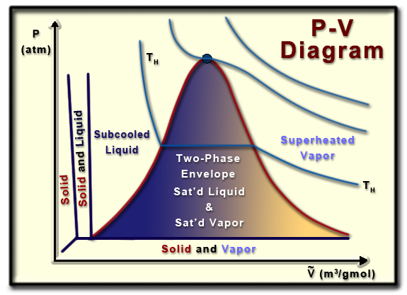
Ch2, Lesson B, Page 6 - P-V Phase Diagram
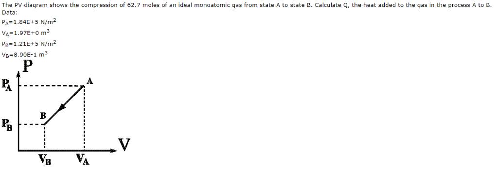
Solved: The PV Diagram Shows The Compression Of 62.7 Moles ...
Thermodynamic processes

Spring trees, 02 May 2021
P-V Diagram Problems and Solutions
Diagrams of Thermodynamic Cycles — Collection of Solved ...
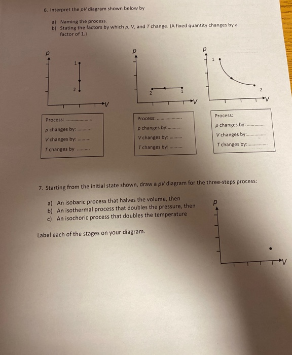
Solved: 6. Interpret The PV Diagram Shown Below By A) Nami ...
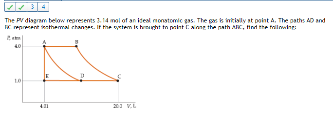
Solved: The PV Diagram Below Represents 3.14 Mol Of An Ide ...
P-V Diagram Problems and Solutions
Solved: Exercise 19.13 Constants The PV Diagram In The Fig ...
Solved: This PV Diagram Shows Three Possible Paths For Cha ...

Thermodynamics Problems with Solutions Three | IIT JEE and ...
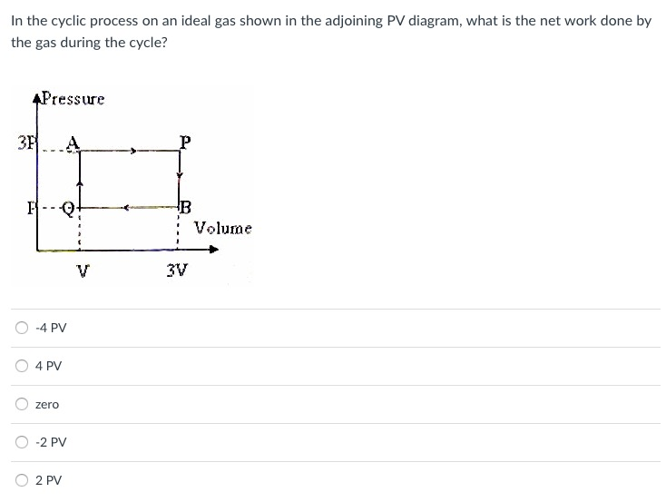
Solved: In The Cyclic Process On An Ideal Gas Shown In The ...

Physics Problems & Solutions: Thermal Physic - Critical ...
0 Response to "39 pv diagram problems and solutions"
Post a Comment