39 Plc Ladder Diagram For Traffic Light
Basics of Ladder Logic - PLC simulator tutorial | Instrumentation and... The ladder diagram contains contact rails on the left, to the right of the diagram, these contact rails are connected to the switching The PLC simulator applications allow to write your program in ladder logic and run it in the simulated PLC. The green light indicates the logical true for each I/O rungs. Ladder-diagram-for-a-Traffic-Control-System's People - Github Help ladder diagram for pedestrian crossing traffic lights. ladder-diagram plc plc-programming. Recently View Projects. Ladder-diagram-for-a-Traffic-Control-System.
PLC Ladder Diagrams - Traffic Lights | Automation & Control... | Forum Network Sites: Programmable Logic Controller - PLC. I am looking for some help on writing a program to control one set of traffic lights, with pedestrian warning lights for a typical UK crossing - the one with a flashing amber and green man.
Plc ladder diagram for traffic light
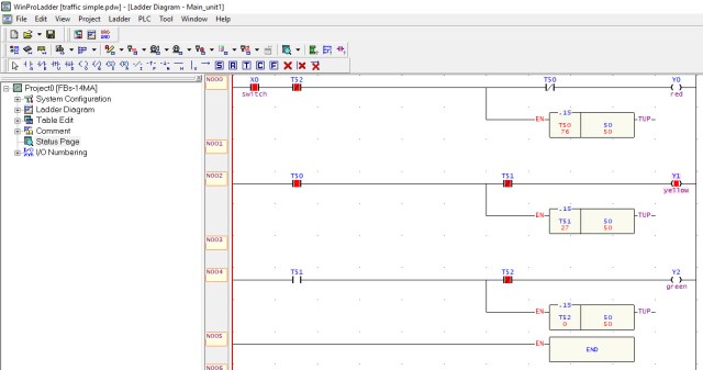
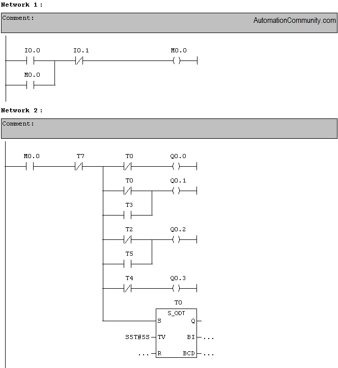
PDF Basics of PLCs Ladder logic (LAD) is one programming language used with PLCs. Ladder logic uses components that resemble elements used in a line diagram format to describe hard-wired control. To accomplish this task, a switch is wired to the input of the PLC and an indicator light is wired to output terminal. #PLC#Timer#Mechatronics PLC ladder diagram for Traffic light signal This video has described the program for traffic light signal. But I have taken only 2 colors in the program. Using Timer On delay, program can be made. Ladder diagram traffic light Ladder diagram traffic light. this ladder diagram for two way traffic light , please see the lay out below: I use omron PLC and I have determine the I/O below
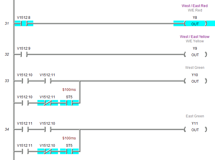
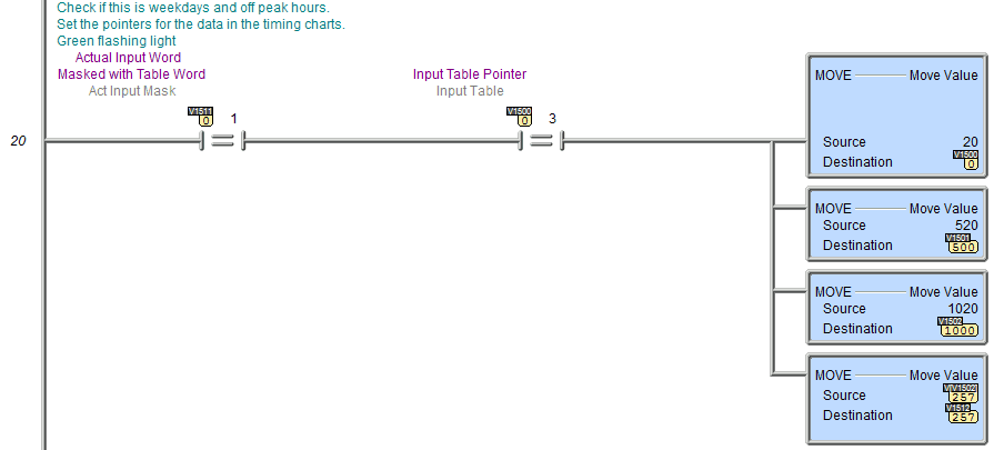
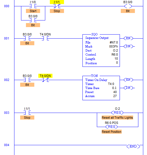
Plc ladder diagram for traffic light. PLC Program to Control Traffic Lights - Sanfoundry Implement controlling of Traffic Lights in PLC using Ladder Diagram programming language. O:2/0 to O:2/5 are used as the output address to Traffic Lights and hence Mask has value 003Fh which means data flow of N7:0/0…N7:10/0 to N7:0/5…N7:10/5 is passed and the remaining N7:0/6…N7... Ladder diagrams and the PLC for electrical engineers - beginners | EEP The ladder diagram has and continues to be the traditional way of representing electrical sequences of operations. These diagrams represent the. This is accomplished using familiar ladder diagrams in a manner that is transparent to the engineer or programmer. Knowledge of PLC operation, scanning... Traffic Light Plc Ladder Diagram - Free Catalogs A to Z 9 hours ago Traffic Light Ladder Logic Diagram. One of the most used applications for a PLC is the traffic lights. PLC Ladder Diagrams - Traffic Lights - Automation. 5 hours ago Nov 3, 2001. #6. One point not raised is the requirement of redundancy in regards to the safety of a traffic light system. Ladder Logic Examples and PLC Programming Examples Traffic Light Ladder Logic Diagram. One of the most used applications for a PLC is the traffic lights. The traffic light PLC program is a combination of timers to control which lights are turned on and for how long time. But some sort of interlock must be there to prevent the green light to be on in...
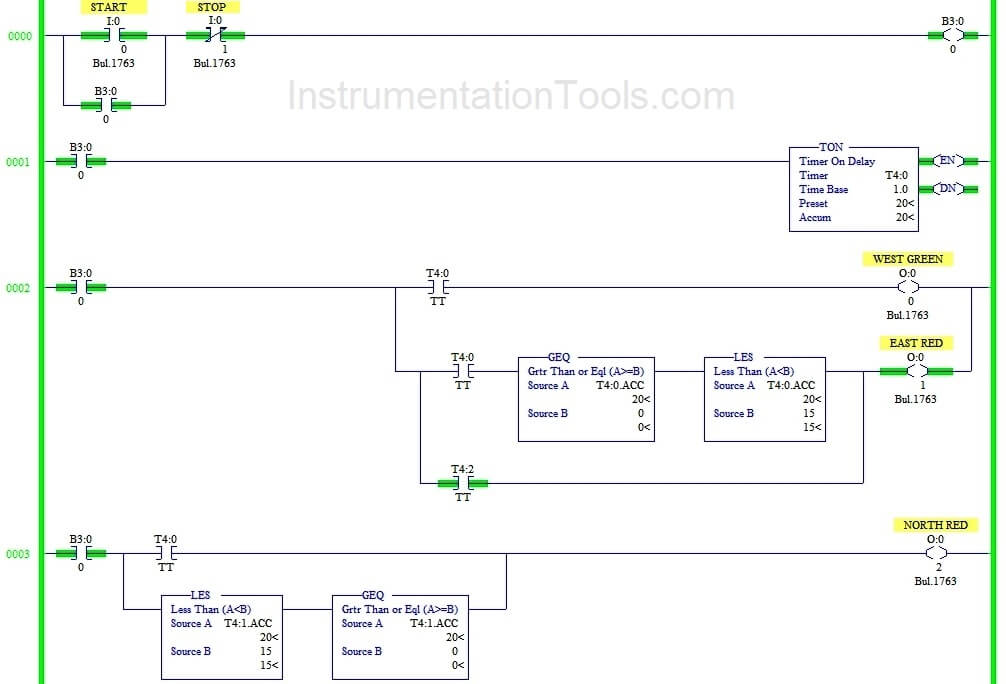
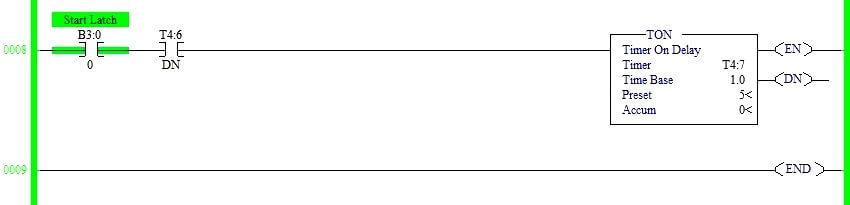
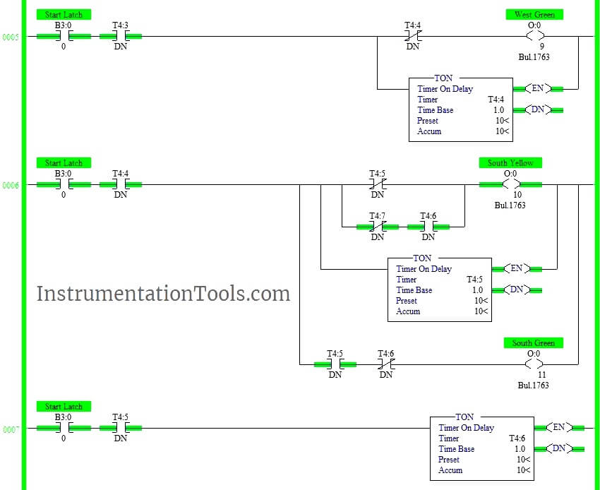
(PDF) Intelligent traffic control system using PLC This project is about controlling a traffic light using PLC, PLC programming languages explained, and ladder logic language chose to program the PLC. Ladder diagrams are programmed by software to monitor the system and helps to improve public transportation services, thereby improving traffic... Introduction and Basic Parts of Ladder Diagram in PLC Programming In the ladder diagram, the programming language that used to create the program to control the PLC system is known as 'Ladder Diagram Language' or 'Ladder Logic Language'. It has signified by the graphical representation, just like electrical wiring for logic control. (At the end of this article, I will... Ladder Diagram - an overview | ScienceDirect Topics Programmable logic controllers can use "ladder logic" or "ladder diagrams (LD)," which is a simplistic programming language included within the The PLC applies this ladder logic by looking at inputs from discrete devices that are connected to the manufacturing equipment, and performing a... 1 thought on "Traffic Light Control using PLC Ladder Logic" PLC Logic Description for 3-way Traffic Control System. The above-explained 3 ways traffic light control using PLC is for example only. It may vary from real-time. We can use this example program to understand the working of timers and comparator block function in AB PLC.
Programmable Logic Controllers (PLCs): Basics, Types... | Electrical4U A SIMPLE explanation of a Programmable Logic Controller (PLC). Learn what a PLC is, its working principle, PLC Basics, the types of PLCs Ladder logic is the simplest form of PLC programming. The figure below shows a ladder diagram and its function block equivalent in Siemens notation. "Ladder" Diagrams | Ladder Logic | Electronics Textbook Read about "Ladder" Diagrams (Ladder Logic) in our free Electronics Textbook. Ladder diagrams are specialized schematics commonly used to document industrial control logic With both sides of the lamp connected to ground, the lamp will be "shorted out" and unable to receive power to light up. traffic light plc ladder diagram - Search Related image with traffic light plc ladder logic diagram wiring diagram. Previous Article 2020 Nhl Playoffs Calgary Flames Vs Winnipeg Jets Game 2. Recommended One-shots in plc programs PLC ladder diagram programming PLC Ladder . state diagram to the SFC Ladder for traffic light and. Experiment 2 traffic light control system for an... Applying the PLC to control the operation of a demand-actuated traffic light system in an intersection. Equipments: Table 1. List of Equipments Traffic Light Pushing S 3 button at any time will stop the motor. Figure 5 shows the ladder diagram for the operation of motor given in Figure 4. I0.0, I0.1, and...
Traffic Light Control using PLC Ladder Logic | Traffic light ...
Ladder diagram traffic light Ladder diagram traffic light. this ladder diagram for two way traffic light , please see the lay out below: I use omron PLC and I have determine the I/O below
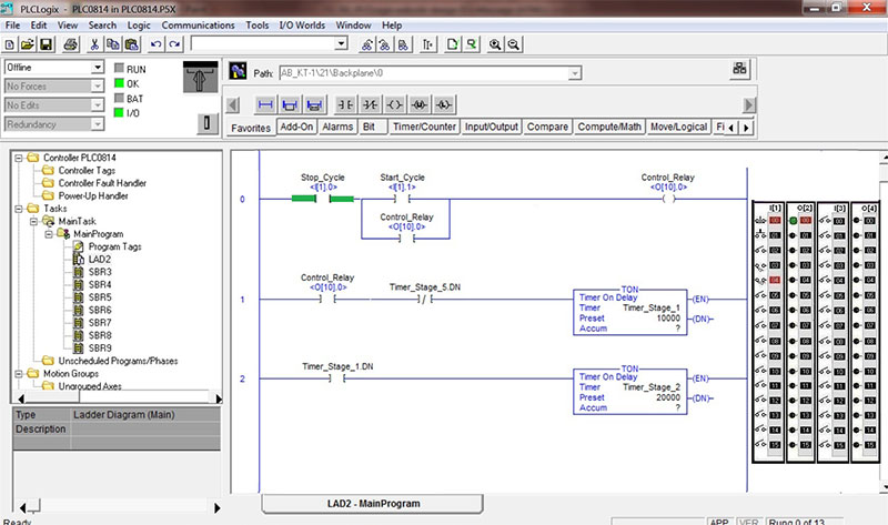
Ladder Logic 302: Data Tracking and Structure Data Type ...
#PLC#Timer#Mechatronics PLC ladder diagram for Traffic light signal This video has described the program for traffic light signal. But I have taken only 2 colors in the program. Using Timer On delay, program can be made.

Using Sequencers - PLCS.net - Interactive Q & A
PDF Basics of PLCs Ladder logic (LAD) is one programming language used with PLCs. Ladder logic uses components that resemble elements used in a line diagram format to describe hard-wired control. To accomplish this task, a switch is wired to the input of the PLC and an indicator light is wired to output terminal.
LogixSim - PLCLogix
Traffic Light Control using PLC Ladder Logic Programming
How to create a ladder logic for 4 way traffic light ...
PLC Program to Control Lights in a Sequence (1) - Sanfoundry

PLC Ladder logic example for beginners: Four-Way traffic ...
traffic light control using plc ladder logic | Acc Automation
traffic light control using plc ladder logic | Acc Automation
PLC Programming Basics using Ladder Logic - Learn Robotics
Programming the traffic light in Logo! Soft Comfort software ...

PLC Program for Traffic Light Control - PLC Tutorial Point
Traffic Light Control using PLC Ladder Logic | Traffic light ...
Traffic Control System using PLC

PLC Program for Traffic Light Control - PLC Tutorial Point
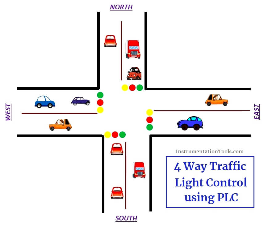
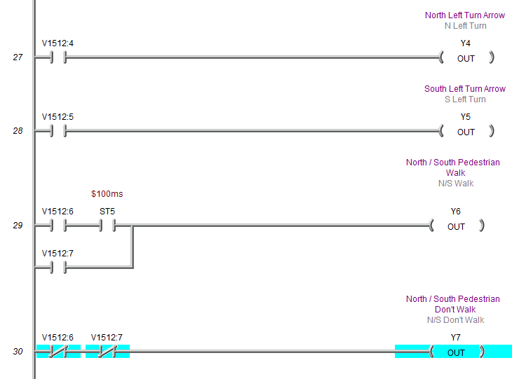
PLC based 4 Way Traffic Light Control System ...

FOUR WAY TRAFFIC CONTROL BY USING PLC – Technical Hub
Traffic light automation control program designed by a ...

Traffic Signal PLC Ladder Programming tutorial - YouTube

Plc traffic light

Ladder Logic Examples and PLC Programming Examples
PLC Timers and Counters, their types and Practical Uses
PLC based 4 Way Traffic Light Control System ...
traffic light control using plc ladder logic | Acc Automation
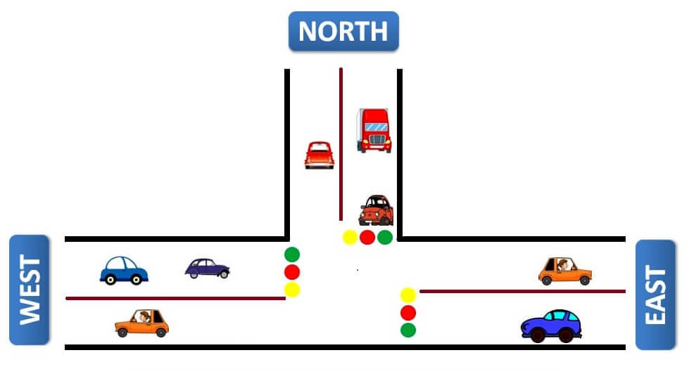
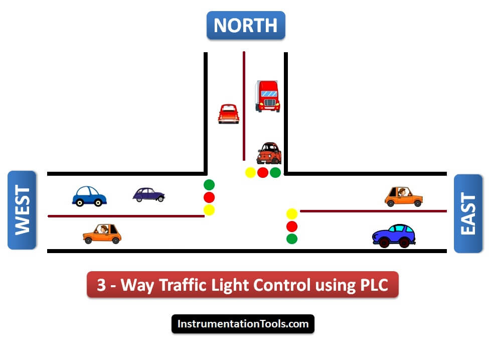
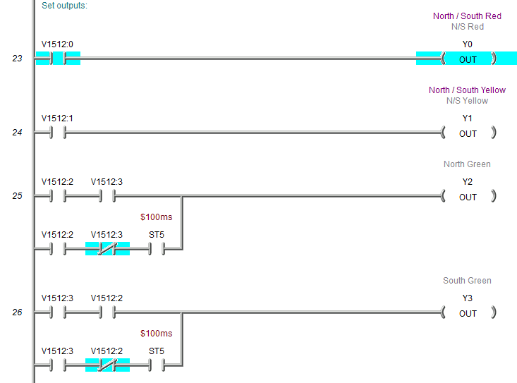
Three way Traffic Light Control using PLC - Automation Community
![I need help with simple ladder logic. [Text] - PLCS.net ...](http://www.plctalk.net/qanda/uploads/Traffic_Light_Timing_Diagram_R2.JPG)
I need help with simple ladder logic. [Text] - PLCS.net ...

Traffic Light Signal Project|2021 Best video| PLC simulation |PLC Programming Tutorial
Traffic Light Control using PLC Ladder Logic | Traffic light ...

Mitsubishi PLC ladder control traffic lights – PLC ONE

PLC Simulation | Automation Studio™ Educational Edition
PLC Program to Control Traffic Lights - Sanfoundry

PDF) Miniature Applications PLC for Traffic Light and ...

PLC Ladder logic basic theory-how it can be useful ...

Traffic light Control example using timer in PLC | PLC PROGRAMMING TUTORIAL FOR BEGINNERS
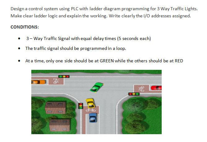
Solved Design a control system using PLC with ladder diagram ...
traffic light control using plc ladder logic | Acc Automation
Traffic Light Control using PLC Ladder Logic Programming
PLC based 4 Way Traffic Light Control System ...
0 Response to "39 Plc Ladder Diagram For Traffic Light"
Post a Comment