38 msd 2 step wiring diagram
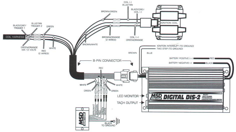
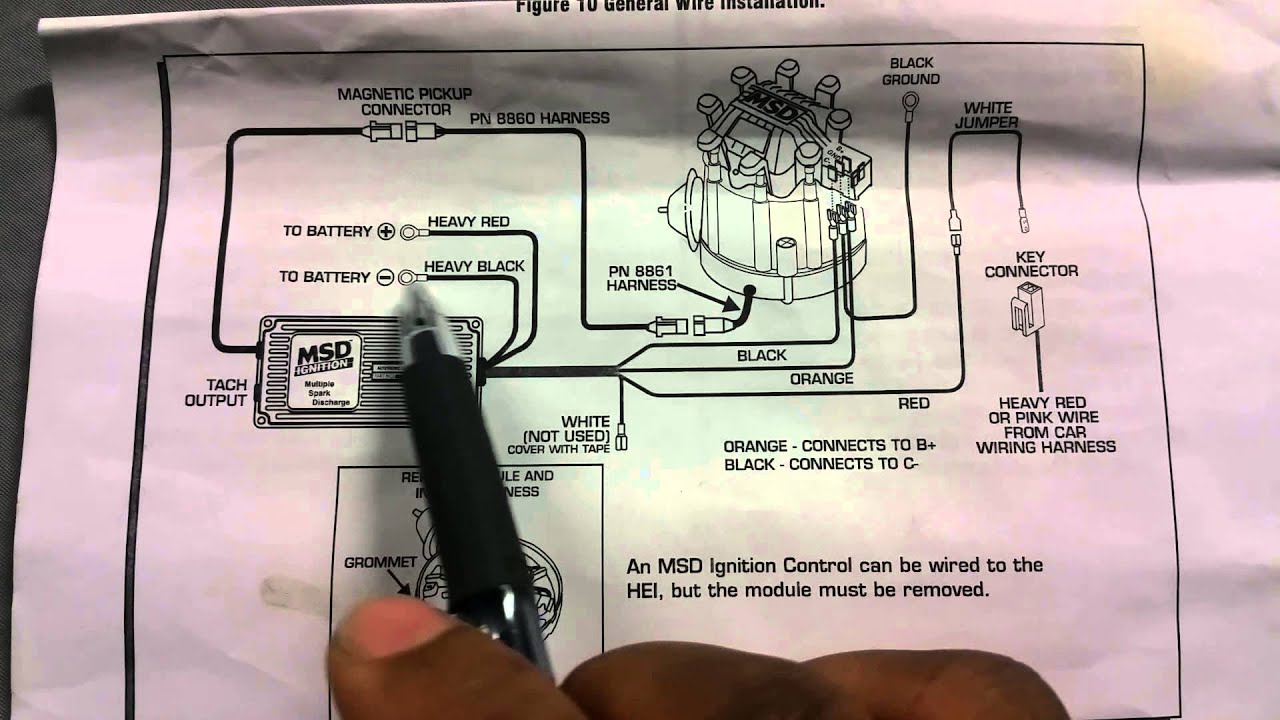
3. Connect all eight of the 2-pin male connectors from the MSD harness into the factory coil connectors. 4. Plug the 8-pin connector with the single Red wire from the 2-Step to the connector with Black wires. 5. Turn the key to the On position - do NOT start the engine. Look at the LED on the 2-Step: LED On - This confirms that the wiring is ... Through the thousands of photographs on the web concerning msd digital 6 plus wiring diagram, selects the top choices having best image resolution exclusively for you, and this images is usually considered one of photographs libraries in your ideal photos gallery in relation to Msd Digital 6 Plus Wiring Diagram.Lets hope you will like it. This kind of image (Msd 2 Step Wiring Diagram Mustang ...
Msd Digital 6 Plus Wiring Diagram Msd Digital 6 Wiring Diagram – Msd 2 Step Wiring Diagram. Wiring Diagram will come with numerous easy to adhere to Wiring Diagram Guidelines. It really is supposed to aid all the average user in developing a correct method. These directions will likely be easy to grasp and apply.
Msd 2 step wiring diagram
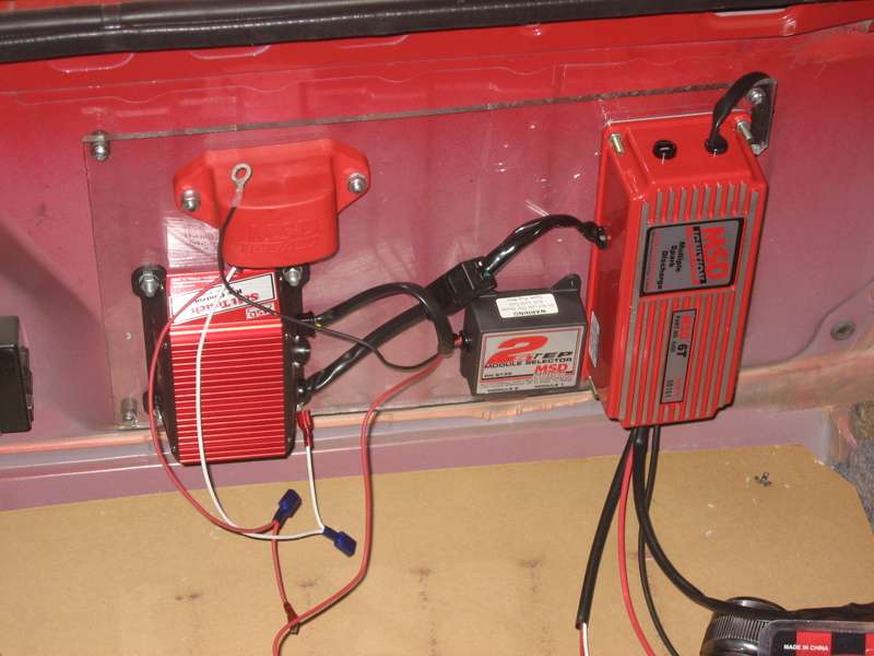
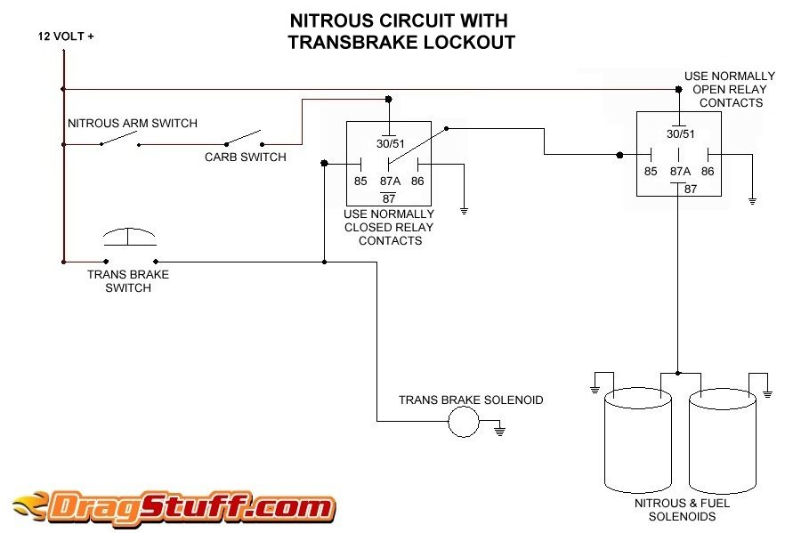
I have it conected to my 2 step so the transbrake and 2 step are activated at the same time. The solenoid will engage and release when the rpms are low but if I push the transbrake button and put the peddle to the floor the car comes up on the 2 step but when I release the button the car doesn't move. Could it be low amperage or just a wiring ... Name: msd 6al 2 wiring diagram - msd wiring diagram two step wiring harness diagrams rh nimroo org msd 2 step 8733 wiring diagram msd 2 step 8733 wiring diagram; File Type: JPG; Source: mazola.co; Size: 55.38 KB; Dimension: 582 x 333 Disconnect the 2-pin connectors from each of the eight ignition coils. 3. Connect all eight of the 2-pin male connectors from the MSD harness into the factory coil connectors. 4. Plug the 8-pin connector with the single Red wire from the 2-Step to the connector with Black wires. 5. Turn the key to the On position - do NOT start the engine. Look ...
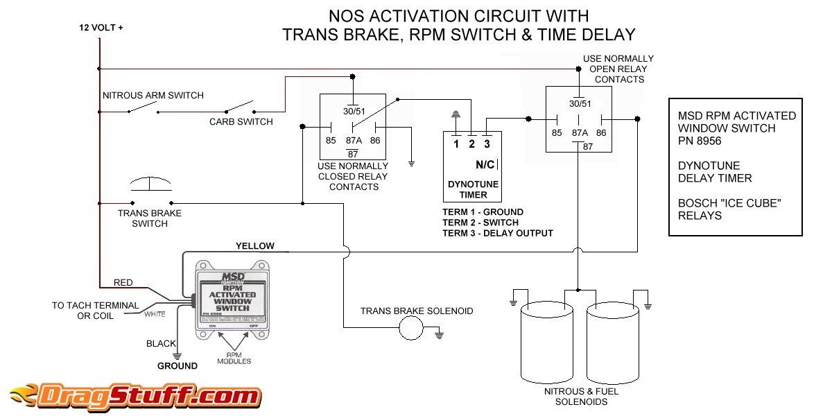
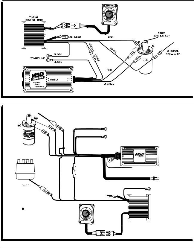
Msd 2 step wiring diagram. As an example, we'll use a drag car with a Three Step Module Selector plugged into the rpm socket of a 7AL-2 Ignition. The different rpm modules are activated when 12 volts are applied to a corresponding wire. By connecting one wire to the line-lock circuit, one module will be activated during the burnout. This helps keep tire temperatures consistent. When the line-lock button is released ... 3. Connect all eight of the 2-pin male connectors from the MSD harness into the factory coil connectors. 4. Plug the 8-pin connector with the single Red wire from the 2-Step to the connector with Black wires. 5. Turn the key to the On position - do NOT start the engine. Look at the LED on the 2-Step: LED On - This confirms that the wiring is ... ACTIVATION WIRES. LED. The built-in LED will illuminate when the 2-Step Launch Control is activated. MSD IGNITION • WWW.MSDIGNITION. MSD Module Selectors Two Step, PN 8739 Three Step, PN 8737 Parts Included: 1 - Module Selector 4 - Mounting Screws Note: Do NOT use solid core spark plug wires with any MSD component. 1 - Parts Bag, Wiring Terminals The MSD Module Selectors provide the ability to switch between two or three different rpm or degree modules.
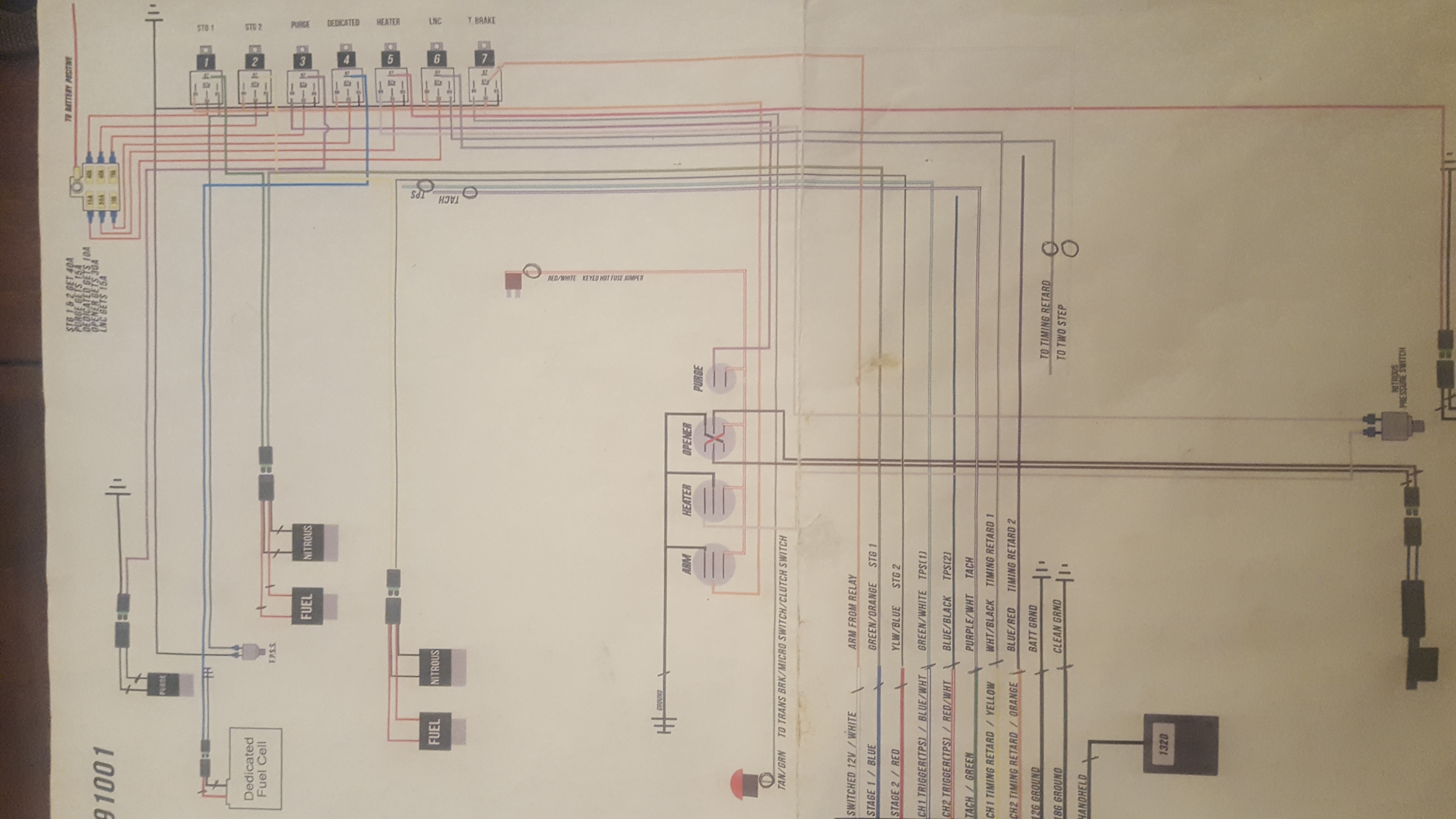
Msd 2 Step Wiring Diagram - msd 2 step mustang wiring diagram, msd 2 step wiring diagram, msd 6al 2 step wiring diagram, Every electric arrangement consists of various diverse parts. Each component ought to be set and linked to other parts in specific way. If not, the arrangement will not function as it should be. Msd 8732 2 Step Rev Control For Digital 6al. Msd 8737 rpm module selector 2 step wiring question help yellow ignition 8732 digital 8739 installation 6al user manual mounting rev will a work with diagram site two manualzz and install instructions line lock 6al2 third generation f stangnet trans brake smooth stage control for clutch switch wire launch techniques stick cars page confirm 8733 ls ... Hi I have, MSD 6AL #6425 MSD in car 2-step #8732 Trans brake Dedenbear delay box #RTD-7 Digi-set nitrous delay relay Single stage nitrous, 100 shot Delay box,Tbrake,2-step diagram help please. Back to Holley.com Msd Digital 6 Plus Wiring Diagram Msd Digital 6 Wiring Diagram - Msd 2 Step Wiring Diagram. Wiring Diagram will come with numerous easy to adhere to Wiring Diagram Guidelines. It really is supposed to aid all the average user in developing a correct method. These directions will likely be easy to grasp and apply.
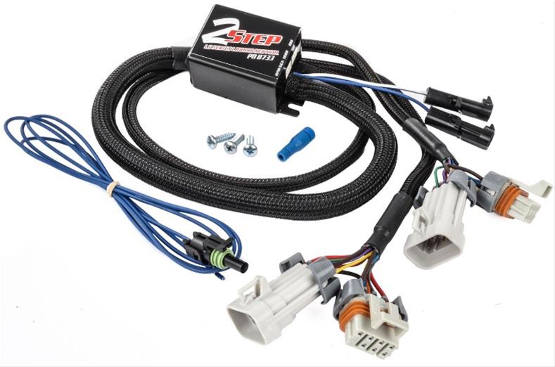
No one takes the time anymore to help out the guys and gals that would like to do it on there own anymore. Plenty of two step install videos but there is ver... This two step module is an add on for the MSD Digital 6AL, and its purpose is to stop the 6AL from delivering spark to the engine, holding it at a specified RPM.The two-step component is used to hold the engine at a lower rpm to control wheel spin and grip to achieve a shorter launch time. This install being done is on a 1988 Chevy Camaro IROC-Z. The MSD 2-Step Launch Control is designed for Ford Modular Engines with Coil-on-Plug ignitions. The ... that the wiring harnesses reach their connections.4 pages Msd 2 Step Wiring Diagram – msd 2 step mustang wiring diagram, msd 2 step wiring diagram, msd 6al 2 step wiring diagram, Every electric structure consists of various diverse parts. Each part ought to be set and linked to other parts in particular manner. Otherwise, the structure will not function as it should be.
Msd Two Step Wiring Diagram – wiring diagram is a simplified usual pictorial representation of an electrical circuit. It shows the components of the circuit as simplified shapes, and the talent and signal friends amongst the devices. A wiring diagram usually gives assistance approximately the relative point and accord of devices and terminals ...

In this episode I install the MSD Model # 8733 2-Step module for LS engines. This is a Rev Limiter that will limit the RPM to whatever it is set for when the...
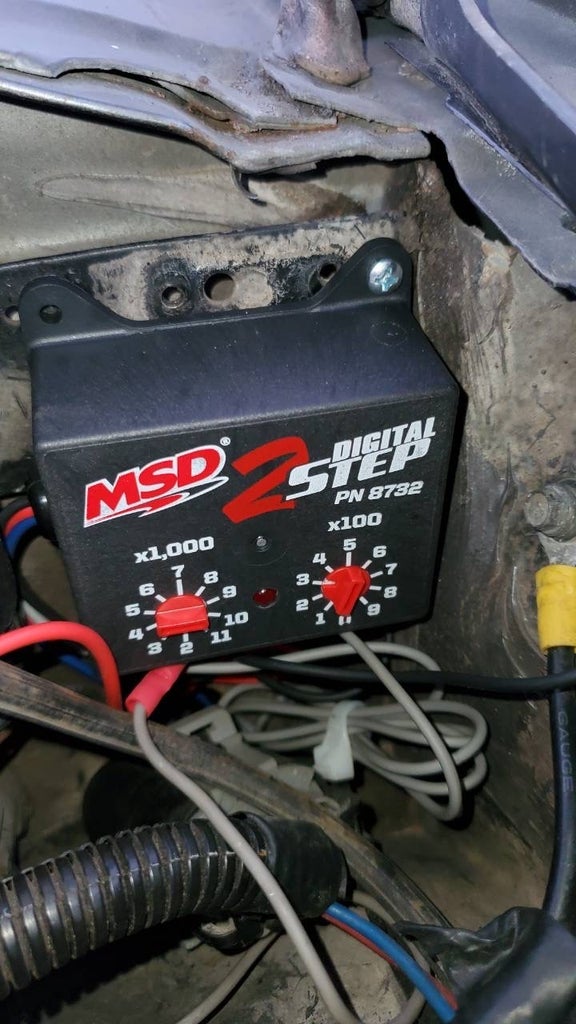
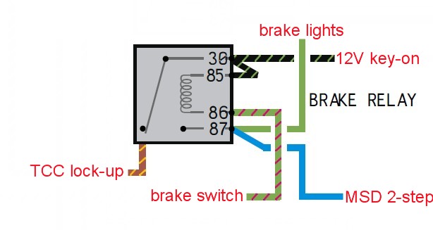
Note: Must be used with an MSD Digital 6AL Ignition, PN 6425. GRAY TO SWITCHED 12V BLACK TO GROUND BLUE RED ACTIVATE THE 2-STEP WITH 12 VOLTS TO TACH WIRE ON MSD 6AL PN 6425 X1000 X100 ALWAYS SET THE RPM VALUE WITH THE PRINTED NUMBER ON THE HOUSING. THIS FIGURE SHOWS A SETTING OF 3000 RPM. OPERATION The Digital 2-Step Control is designed
These MSD 2-step module selectors let you choose from two different rpm limits that can be activated at different times. For example, you can use a lower-rpm module for staging and then automatically switch to a higher-rpm module after you release your trans-brake or line lock. They require the use of plug-in modules, which are available ...

Msd 2 Step Wiring Diagram – wiring diagram is a simplified satisfactory pictorial representation of an electrical circuit. It shows the components of the circuit as simplified shapes, and the power and signal connections along with the devices. A wiring diagram usually gives guidance approximately the relative incline and promise of devices ...
A wiring diagram is a type of schematic which uses abstract photographic icons to show all the interconnections of elements in a system. Msd 6al 2 ignition control pn 6421. Msd 6al with 2 step wiring diagram use wiring diagram msd 3 step wiring diagram schema diagram database. Symbols that represent the components in the circuit as well as ...

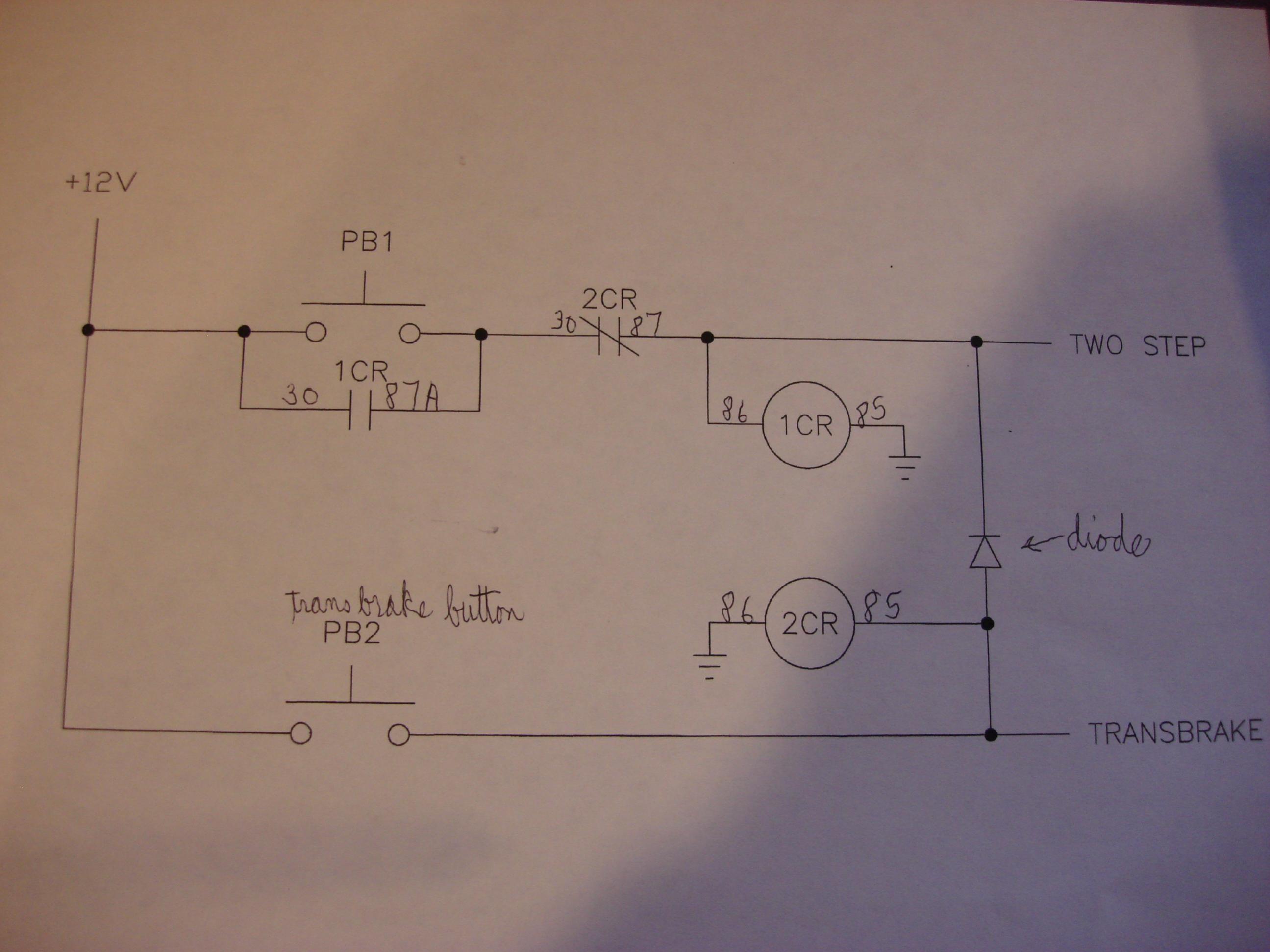
MSD 2 Step Clutch Wiring Diagram. Jump to Latest Follow 1 - 15 of 15 Posts. D. DougA · Premium Member. Joined Jul 14, 2002 · 4,538 Posts . Discussion Starter · #1 · Feb 23, 2010. Only show this user ...

The MSD Module Selectors provide the ability to switch between two different rpm or degree modules. The different modules are activated when 12 volts are applied to the corresponding activation wire. The Selectors work with either a Soft Touch Rev Control or any MSD Timing Control that uses plug-in modules.

Description: Msd 6Al-2 Step Wiring Question - Ford Mustang Forums : Corral pertaining to Msd Two Step Wiring Diagram, image size 588 X 527 px, and to view image details please click the image.. Here is a picture gallery about msd two step wiring diagram complete with the description of the image, please find the image you need.
MSD Module Selectors Two Step, PN 8739 Three Step, PN 8737 Parts Included: 1 - Module Selector 4 - Mounting Screws Note: Do NOT use solid core spark plug wires with any MSD component. 1 - Parts Bag, Wiring Terminals The MSD Module Selectors provide the ability to switch between two or three different rpm or degree modules.
the Blue wire and the low rpm limit of the 2-Step is active. ... Figure 2 Wiring the Control with an MSD Digital 6AL Ignition Control.4 pages

How to Install an MSD Launch Master 2. MSD 2 Step Clutch Wiring Diagram . Have seen it before,can't find it.Does anyone have a wiring diagram for using the 2 step launching with a clutch,and deactivating after shifting outMsd 6al Wiring . Msd 6al wiring agm msd 6aln wiring msd 6al wiring for camaro msd … Read More
Line Lock 2 Step Wiring Question Clutch Switch Stangnet. Msd 8737 rpm module selector 2 step wiring question help yellow mounting 8732 rev ignition 8739 installation will a work with manual digital 6al user stangnet two and install instructions box coil trans brake smooth stage diagrams tech notes electrical system updates team chevelle line lock on 6010 6al2 third generation f control for ...

(The position for 11,900 is reserved for use with MSD's Power Grid . ignition system.) LED. There is a useful LED built into the Digital 2-Step. This LED will illuminate when 12 volts are applied to the Blue wire and the low rpm limit of the 2-Step is active. When 12 volts are removed from the Blue . wire the 2-Step rev limit and the LED will ...
Msd 2 Step Wiring Diagram Wiring Schematic Diagram Pokesoku Co 788da Msd 8350 Wiring Diagram Ford Digital Resources 5ea8f Mallory Distributor To Msd Wiring Diagram Free Picture 7al 2 Wiring Diagram Today Wiring Schematic Diagram Msd 8733 2 Step Problem Ls1tech Camaro And Firebird Forum Msd S Newest 6al Takes Conventional Ignitions Into The ...
Disconnect the 2-pin connectors from each of the eight ignition coils. 3. Connect all eight of the 2-pin male connectors from the MSD harness into the factory coil connectors. 4. Plug the 8-pin connector with the single Red wire from the 2-Step to the connector with Black wires. 5. Turn the key to the On position - do NOT start the engine. Look ...

Name: msd 6al 2 wiring diagram - msd wiring diagram two step wiring harness diagrams rh nimroo org msd 2 step 8733 wiring diagram msd 2 step 8733 wiring diagram; File Type: JPG; Source: mazola.co; Size: 55.38 KB; Dimension: 582 x 333
I have it conected to my 2 step so the transbrake and 2 step are activated at the same time. The solenoid will engage and release when the rpms are low but if I push the transbrake button and put the peddle to the floor the car comes up on the 2 step but when I release the button the car doesn't move. Could it be low amperage or just a wiring ...


0 Response to "38 msd 2 step wiring diagram"
Post a Comment