38 block diagram reduction problems and solutions
EE C128 / ME C134 Spring 2014 HW4 - Solutions UC Berkeley 5. Block Diagram To Transfer Function Reduce the system shown below to a single transfer function, T(s) = C(s)=R(s). Solution: Push G 2(s) to the left past the summing junction. Collapse the summing junctions and add the parallel transfer functions. Rev. 1.0, 02/23/2014 4 of 9 Example of Block Diagram Reduction. Till now we have seen the important rules to be kept in mind while reducing the block diagram. Let us now see an example to have a better understanding of the same. First, see the procedural steps to be followed for solving block diagram reduction problems:
Block Diagram Reduction Rules. In many practical situations, the block diagram of a Single Input‐Single Output (SISO), feedback. control system may involve several feedback loops and summing points. In principle, the block. diagram of (SISO) closed loop system, no matter how complicated it is, it can be reduced to the.
Block diagram reduction problems and solutions
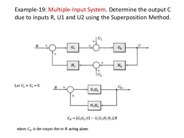
Applying Skill & Knowledge · Continuing with different Education Sector Since-2003 Superposition of Multiple Inputs: To nd the total response in the case of multiple inputs: 1 Set all inputs except one equal to zero. 2 Transform the block diagram to canonical form, using the reduction techniques. 3 Calculate the response due to the chosen input acting alone. 4 Repeat step 1 to 3 for the other remaining inputs. 5 Algebraically add all of the responses (output) obtained in ... Solved by A.Devasena., Associate Professor., Dept/ECE Page 7 fEC2255- Solved Problems in Control System IV Semester ECE Reduce minor feedback loops. As for as possible shift summing point to the left and take-off point to the right. Repeat the above steps till canonical form is obtained.
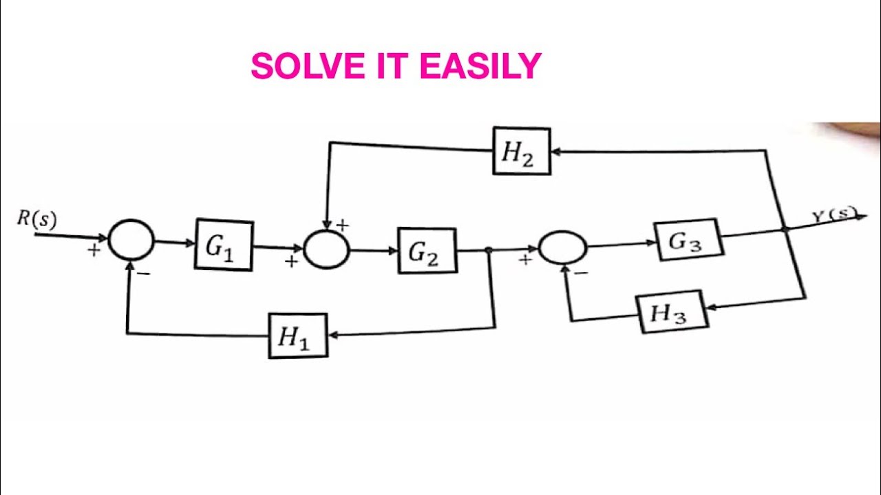
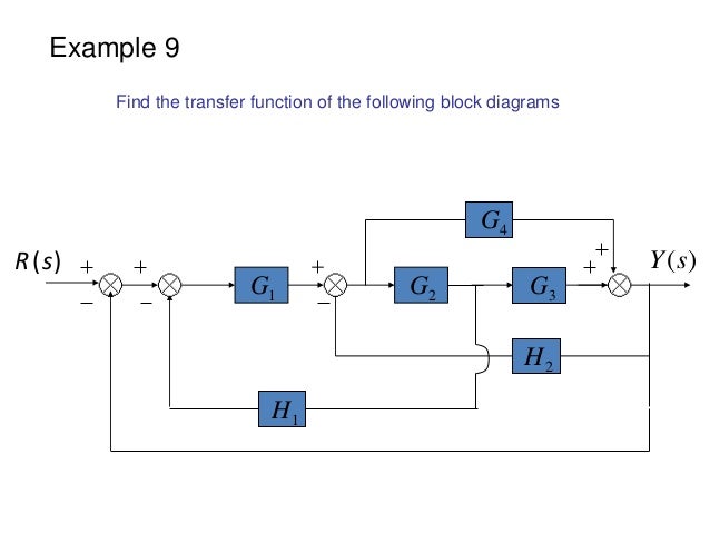
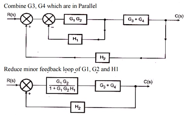
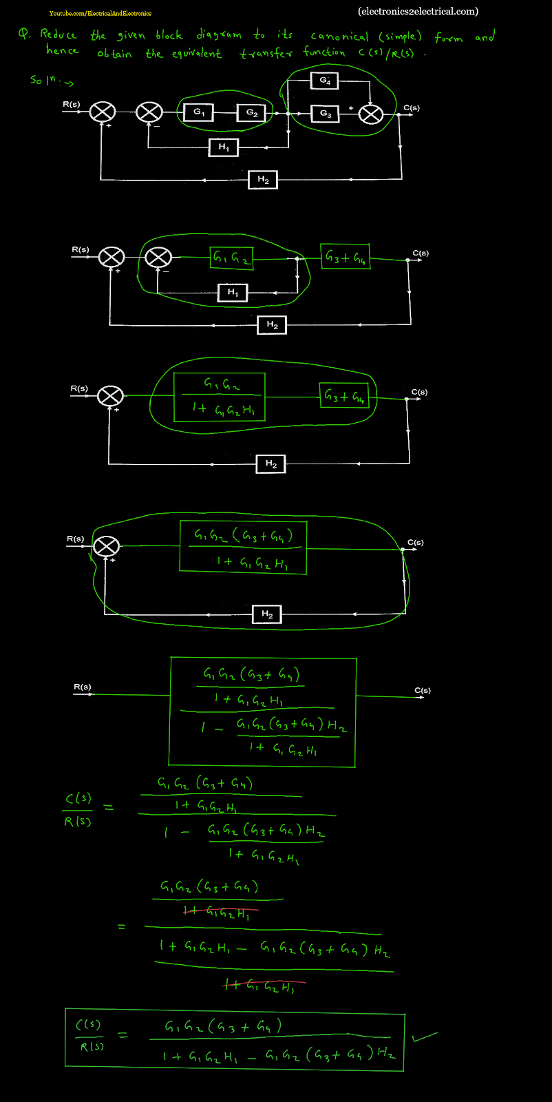
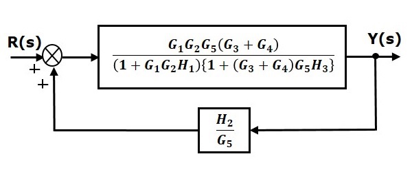
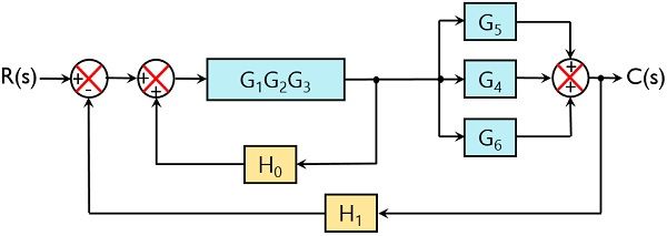
Block diagram reduction problems and solutions. Procedure to solve Block Diagram Reduction Problems. Step 1: Reduce the blocks connected in series Step. 2: Reduce the blocks connected in parallel Step 3: Reduce the minor feedback loops. Step 4: Try to shift take off points towards right and Summing point towards left. Step 5: Repeat steps 1 to 4 till simple form is obtained. Block diagram Examples. 1. Control System Engineering Kuntumal Sagar M. B.TECH (E.E) UID-U41000000484 Email: skuntmal@yahoo.com TOPIC BLOCK DIAGRAM EXAMPLES. 2. Example 9 Find the transfer function of the following block diagrams 2G 3G1G 4G 1H 2H ) (sY) (sR. Given: The system shown in the block diagram has one input signal, Rs(), and one output signal, Ys(). Find: Using block diagram reduction, find the transfer function () Y s R. Solution: First, it should be noted that there are many solution paths that can be taken to reduce complex systems using block diagram reduction techniques. Get Block Diagram Reduction Technique Multiple Choice Questions (MCQ Quiz) with answers and detailed solutions. Download these Free Block Diagram Reduction Technique MCQ Quiz Pdf and prepare for your upcoming exams Like SSC, Railway, UPSC, State PSC.
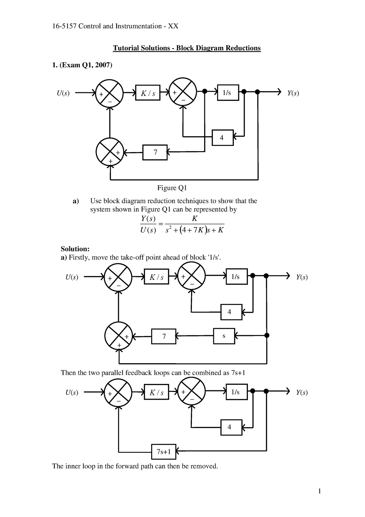
NPTEL provides E-learning through online Web and Video courses various streams. Block Diagram Reduction Solved Examples - 3 Numerical Solutions For Students of B.Tech, B.E, MCA, BCA, B.Sc., M.Sc., Courses - As Per IP University Syllabus and Other Engineering Courses Block Diagram Reduction Examples and solutions Pdf . Diagrams Block Diagram Control System Pdf Dolgular Block Diagram Amazing Block Reduction Rules Motif Electr! Tutorial Solutions - Block Diagram Reductions (Exam Q1, 2007) a) Use block diagram reduction techniques to show that the system shown in Figure Q1 can be represented by. s K s K. K U s. Y s )( 4 7)( 2. Solution: a) Firstly, move the take-off point ahead of block '1/s'. More Solved Problems on Block Diagram Reduction Technique step by step. Continue on app. Block Diagram Reduction Techniques and Signal Flow Graph. 5 lessons • 46m . 1. Repersentation of Block Diagram . 8:59mins. 2. Rules of Block Diagram Reduction Technique. 8:00mins. 3.
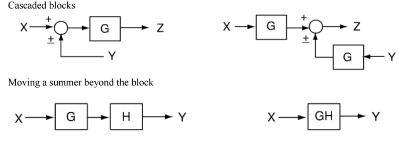
Block Diagram Reduction Rules Block diagram reduction rules help you to minimize the block diagram thus solving the equations quickly. Below table represents block diagram reduction rules in the control system Using the above rules you have to follow below simple steps to solve the block diagrams: 1. Combine all cascade blocks 2. K. Webb MAE 4421 3 Block Diagrams In the introductory section we saw examples of block diagrams to represent systems, e.g.: Block diagrams consist of Blocks-these represent subsystems - typically modeled by, and labeled with, a transfer function Signals- inputs and outputs of blocks -signal direction indicated by Black Diagram Reduction, Signal Flow Graph, Mason's Gain formula, Final value theorem - Topicwise Questions in Control Systems (1987 -2015) ... Despite the percentage of negative feedback, control systems still have problems of Instability because the a) components used have non-linearity b) dynamic equations of the sub-systems are not know ... Moving a summing point beyond of a block : Moving a summing point ahead of a block : Let us take an example. EXAMPLE : Using the block diagram reduction technique, find the transfer function of the control system represented by the following block diagram. SOLUTION : Can be solved in following steps by applying above reduction rules .
ing block diagrams using block diagram algebra, in addition to the three basic rules described in part A (Figs 2 to 4), various numbers of other rules are introduced in various textbooks with regard to the relocation of the summing/pickoff point(s). Each rule involves a pair of equivalent block diagram. For example, Fig. 5 lists some of the ...
Block Diagram Reduction Rules Table 1: Block Diagram Reduction Rules Table 2: Basic rules with block diagram transformation . Example 1: Example 2: Example 3: Example 4: Example5: ECE 680 Modern Automatic Control Routh’s Stability Criterion June 13, 2007 1 ROUTH’S STABILITY CRITERION

Block Diagram • It represents the structure of a control system. • It helps to organize the variables and equations representing the control system. It is composed of: • boxes, that represents the components of the system including their causality; • Lines with arrows, that represent the actual
BLOCK DIAGRAM REDUCTION Block diagram is a pictorial representation of a control system showing inter-relation between the transfer function of various components. The block diagram is obtained after ... The solution of this type of problems will be based on detecting the combinations that match
5. (i) Using block diagram reduction technique, find the closed loop transfer function C/R of the system whose block diagram is shown below. (ii) Construct the signal flow graph for the following set of simultaneous equations and obtain the overall transfer function using Mason‘s gain formula. X2 = A21X1 + A23X3. X3 = A31X1 + A32X2 + A33X3
block diagram reduction solved problems. 1. Block Diagram Reduction Problems - Ameya P. Nijasure napradeep@mes.ac.in Do visit Block Diagram Reduction rules (.ppt) 2. Problem 01 Simplify the following block Diagram & determine closed loop transfer function. 3. Problem 01 STEP 01STEP 01 Rule 02: Blocks in Parallel. 4.
Transfer Functions, Block Diagrams, and Signal Flow Graphs Problems 2.1 Compute the transfer function of the depicted block diagram a. By reduction H2(s) G3(s) Hi(s) H3(s) Solution 45 Gds) a. By applying transformation 7 (Table F2.1), the branch point at the left of the block with transfer function G4(s) is moved at the right of G4(s).
65 Years of Excellence · The Veer Surendra Sai University of Technology (VSSUT) Odisha was formed by Orissa Act 9 of 2009 by converting University College of Engineering (UCE), Burla to a non-affiliating Unitary University and came into force by issue of notification by the Industries Department, ...

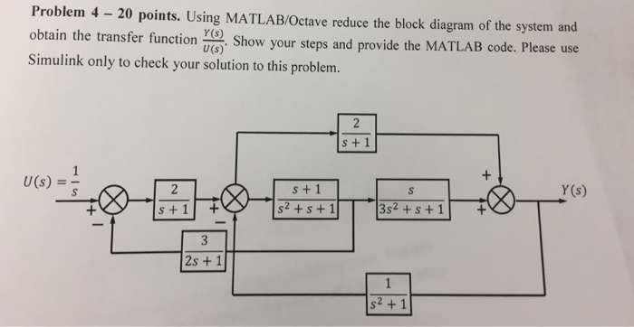
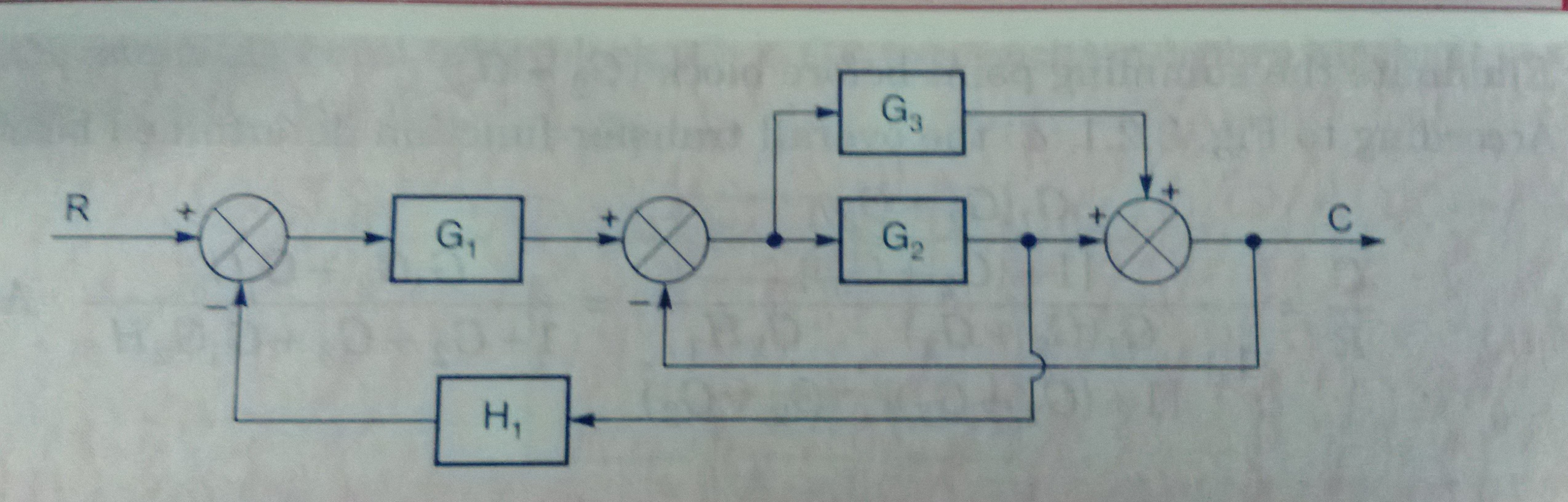
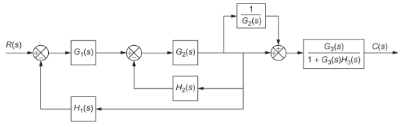
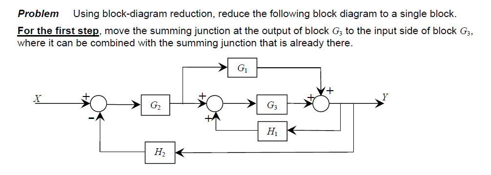
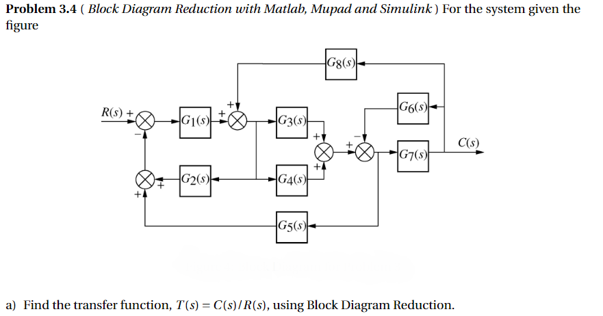
Transcribed image text: Problem 1: Using the block diagram reduction technique to simplify the block diagram shown below and obtain the closed-loop transfer function C(s)/R(s).Problem 2: Using the block diagram reduction technique to find the closed-loop transfer function of the system shown below, Y(s)/R(s).
Mason™s rule is useful for solving relatively complicated block diagrams by hand. It yields the solution in the sense that it provides an explicit inputŒoutput relationship for the system represented by the diagram. The advantage compared with path-by-path block-diagram reduction is that it is systematic and algorithmic rather than problem ...
Keyur Rana Chemical Engineering · Hello everyone, First of all, I would like to thank the whole team of SRICT. Here I learned not just bookish things, but learned how to live as a true young man. I got connected with SRICT four years back, here I got in depth knowledge of engineering.
Block diagram reduction problems and solutions | Block Diagram Problems | Simplify the block diagram | Block diagram reduction solved examples | Find transfe...
Block Diagram RepresentationIt is the pictorial representation of the control systemTransfer function can be derived from block diagram of control system ...
Problem 1 on Block Diagram Reduction watch more videos at https://www.tutorialspoint.com/videotutorials/index.htm Lecture By: Mrs. Gowthami Swarna, Tutorials

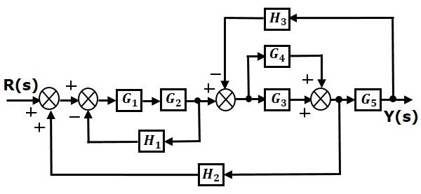
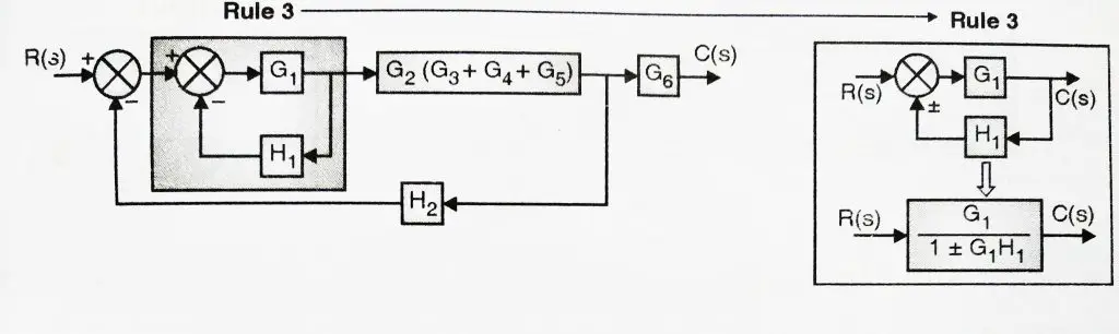
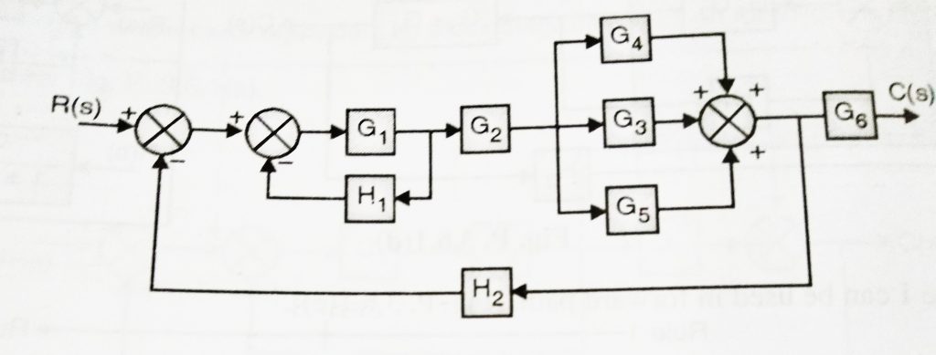
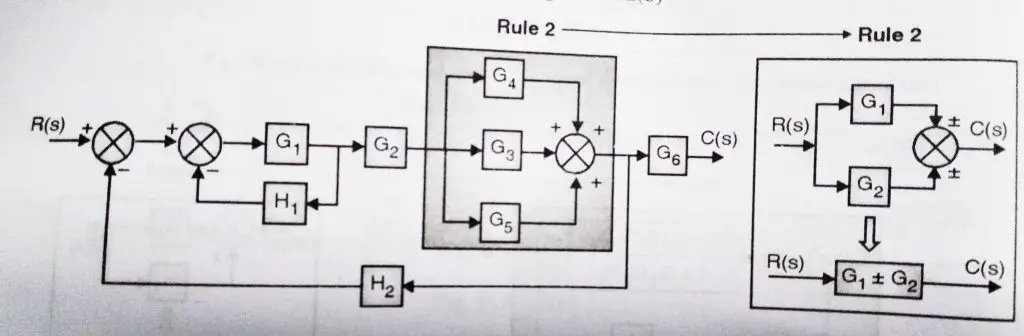
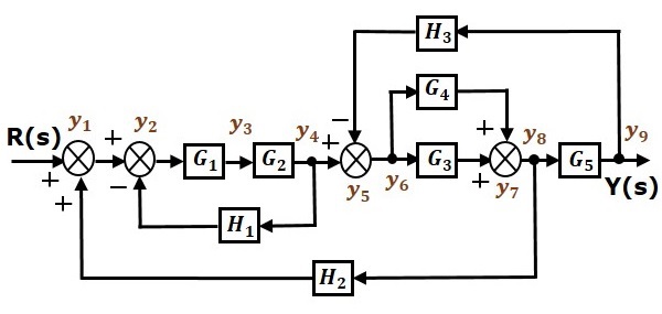
Let us simplify (reduce) this block diagram using the block diagram reduction rules. Step 1 − Use Rule 1 for blocks G 1 and G 2. Use Rule 2 for blocks G 3 and G 4. The modified block diagram is shown in the following figure. Step 2 − Use Rule 3 for blocks G 1 G 2 and H 1. Use Rule 4 for shifting take-off point after the block G 5.

Reduction of the block diagram shown in Figure 3-44. Figure 3-46 Block diagram of a system. Solution. The block diagram of Figure 3-44 can be modified to that shown in Figure 3-45(a). Eliminating the minor feedforward path, we obtain Figure 3-45(b), which can be simplified to
Solved by A.Devasena., Associate Professor., Dept/ECE Page 7 fEC2255- Solved Problems in Control System IV Semester ECE Reduce minor feedback loops. As for as possible shift summing point to the left and take-off point to the right. Repeat the above steps till canonical form is obtained.

Superposition of Multiple Inputs: To nd the total response in the case of multiple inputs: 1 Set all inputs except one equal to zero. 2 Transform the block diagram to canonical form, using the reduction techniques. 3 Calculate the response due to the chosen input acting alone. 4 Repeat step 1 to 3 for the other remaining inputs. 5 Algebraically add all of the responses (output) obtained in ...

Applying Skill & Knowledge · Continuing with different Education Sector Since-2003


0 Response to "38 block diagram reduction problems and solutions"
Post a Comment